


TK-90
HF TRANSCEIVER
INSTRUCTION MANUAL
TRANSCEPTOR HF
MANUAL DE INSTRUCCIONES
© B62-1866-10 (M)
09 08 07 06 05 04 03 02 01

HF TRANSCEIVER
TK-90
INSTRUCTION MANUAL
ENGLISH
THANK YOU
Thank you for choosing KENWOOD for your radio telecommunication applications. We believe this easy-to-use transceiver will provide dependable communications to keep vehicles and personnel operating at peak efficiency.
KENWOOD transceivers incorporate the latest in advanced technology. As a result, we feel strongly that you will be pleased with the quality and features of this product.
NOTICES TO THE USER
Government law prohibits the operation of unlicensed transmitters within the territories under government control.
Illegal operation is punishable by fine and/or imprisonment.
Refer service to qualified technicians only.
SAFETY: It is important that the operator is aware of, and understands, hazards common to the operation of any transceiver.
EXPLOSIVE ATMOSPHERES (GASES, DUST, FUMES, etc.)
Turn OFF your transceiver while taking on fuel or while parked in gasoline service stations. Do not carry spare fuel containers in the trunk of your vehicle if your transceiver is mounted in the trunk area.
INJURY FROM RADIO FREQUENCY TRANSMISSIONS
Do not operate your transceiver when somebody is either standing near to or touching the antenna, to avoid the possibility of radio frequency burns or related physical injury.
DYNAMITE BLASTING CAPS
Operating the transceiver within 150 m (500 feet) of dynamite blasting caps may cause them to explode. Turn OFF your transceiver when in an area where blasting is in progress, or where “TURN OFF TWO-WAY RADIO” signs have been posted. If you are transporting blasting caps in your vehicle, make sure they are carried in a closed metal box with a padded interior. Do not transmit while the caps are being placed into or removed from the container.
PRECAUTIONS
Observe the following precautions to prevent fire, personal injury, and transceiver damage.
•Do not attempt to configure the transceiver while driving; it is too dangerous.
•Do not disassemble or modify the transceiver for any reason.
•Do not expose the transceiver to long periods of direct sunlight, nor place it near heating appliances.
•Do not place the transceiver in excessively dusty, humid, or wet areas, nor on unstable surfaces.
•If an abnormal odor or smoke is detected coming from the transceiver, switch the transceiver power off immediately, and contact your KENWOOD dealer.
•Use of the transceiver while you are driving may be against traffic laws. Please check and observe the vehicle regulations in your area.
•Do not use options not specified by KENWOOD.
The transceiver operates in 12 V negative ground systems only! Check the battery polarity and voltage of the vehicle before installing the transceiver.
Use only the supplied DC power cable or a KENWOOD optional DC power cable.
Do not insert metal objects into the cooling fan.
Do not cut and/or remove the fuse holder on the DC power cable. Improper connections and/or current surges may cause smoke or fire.
For passenger safety, install the transceiver securely using the supplied mounting bracket and screw set so the transceiver will not break loose in the event of a collision.
i
CONTENTS
PREPARATION / INSTALLATION ............................. |
1 |
UNPACKING AND CHECKING EQUIPMENT...... |
1 |
SUPPLIED ACCESSORIES ......................................... |
1 |
BASE STATION INSTALLATION .......................... |
1 |
FOOT PADS ......................................................... |
1 |
ANTENNA CONNECTION ........................................... |
1 |
GROUND CONNECTION ........................................... |
1 |
DC POWER SUPPLY CONNECTION ............................ |
2 |
MOBILE INSTALLATION ...................................... |
2 |
INSTALLING THE TRANSCEIVER .................................. |
2 |
ANTENNA CONNECTION ........................................... |
2 |
GROUND CONNECTION ........................................... |
3 |
DC POWER CABLE CONNECTION ............................. |
3 |
GETTING ACQUAINTED .......................................... |
4 |
FRONT PANEL ..................................................... |
4 |
REAR PANEL ....................................................... |
4 |
DISPLAY ............................................................... |
5 |
MICROPHONE (OPTIONAL) ............................... |
6 |
PROGRAMMABLE FUNCTIONS ......................... |
7 |
BASIC OPERATIONS ................................................ |
8 |
SWITCHING POWER ON/OFF ............................ |
8 |
ADJUSTING THE VOLUME ................................. |
8 |
SELECTING A CHANNEL .................................... |
8 |
DIRECT FREQUENCY ENTRY ................................... |
8 |
SELECTING A MODE ........................................... |
8 |
DATA OPERATION .................................................. |
8 |
TRANSMITTING ................................................... |
9 |
VOX (VOICE-OPERATED TRANSMISSION) ................ |
9 |
CW KEYING ........................................................ |
9 |
CHANGING THE TRANSMIT POWER .......................... |
9 |
TIME-OUT TIMER ................................................. |
9 |
OVERHEATING ...................................................... |
9 |
SQUELCH/ MONITOR ....................................... |
10 |
SQUELCH LEVEL ................................................ |
10 |
CHANNEL MONITORING ........................................ |
10 |
MENU SETUP ......................................................... |
11 |
ACCESSING THE MENU ................................... |
11 |
MENU CONFIGURATION .................................. |
11 |
SCAN ....................................................................... |
12 |
BUSY FREQUENCY STOP ................................ |
12 |
SCAN RESUME TYPES ......................................... |
12 |
PREFERRED SCAN ........................................... |
12 |
ADD TO SCAN/ REMOVE FROM SCAN ........... |
12 |
SCAN REVERT CHANNEL ................................ |
12 |
SELECTIVE CALLS ................................................. |
13 |
ACTIVATING SELCALL MODE .......................... |
13 |
MANUAL SELCALLS .......................................... |
13 |
SELECTING A STATION USING THE TRANSCEIVER KEYS .. |
13 |
SELECTING A STATION USING A MICROPHONE KEYPAD ... |
13 |
DIRECT SELCALLS ........................................... |
13 |
RECEIVING A SELCALL .................................... |
13 |
MEMORY CALLS ............................................... |
13 |
SELECTING A MEMORY CALL USING THE |
|
TRANSCEIVER KEYS ............................................. |
13 |
SELECTING A MEMORY CALL USING A |
|
MICROPHONE KEYPAD .......................................... |
14 |
MANUAL STATUS CALLS .................................. |
14 |
MAKING A STATUS CALL USING THE |
|
TRANSCEIVER KEYS ............................................. |
14 |
MAKING A STATUS CALL USING A |
|
MICROPHONE KEYPAD .......................................... |
14 |
DIRECT STATUS CALLS ................................... |
15 |
OPTIONAL VOICE MESSAGES ........................ |
15 |
RECEIVING A STATUS CALL ............................ |
15 |
REVIEWING MESSAGES IN THE STACK MEMORY ......... |
15 |
SEND THE GPS DATA ....................................... |
16 |
MANUALLY SENDING THE GPS DATA .................... |
16 |
GPS POLLING ................................................... |
16 |
SHORT TEXT MESSAGES ................................ |
16 |
ADVANCED OPERATIONS ..................................... |
17 |
DIRECT CHANNEL ............................................ |
17 |
SCRAMBLER ..................................................... |
17 |
CHANGING THE SCRAMBLER CODE ........................ |
17 |
VOX (VOICE-OPERATED TRANSMIT) |
|
SETUP ................................................................ |
17 |
VOX GAIN ....................................................... |
17 |
ANTI-VOX GAIN ............................................... |
17 |
VOX DELAY TIME .............................................. |
18 |
ANTENNA TUNER ............................................. |
18 |
EMERGENCY ..................................................... |
18 |
CLARIFIER ......................................................... |
18 |
NOISE BLANKER ............................................... |
19 |
LCD BRIGHTNESS ............................................ |
19 |
POWER-ON TEXT.............................................. |
19 |
DISPAY NAME/ FREQUECY .............................. |
19 |
PRE-AMPLIFIER/ ATTENUATOR ...................... |
19 |
AUXILIARY ......................................................... |
19 |
VGS-1 OPTIONAL VOICE GUIDE & |
|
STORAGE UNIT ...................................................... |
20 |
VOICE MEMOS .................................................. |
20 |
RECORDING A VOICE MEMO .................................. |
20 |
PLAYING BACK A VOICE MEMO .............................. |
20 |
DELETING A VOICE MEMO ..................................... |
20 |
VOICE MESSAGES ........................................... |
20 |
RECORDING A VOICE MESSAGE .............................. |
20 |
PLAYING BACK A VOICE MESSAGE .......................... |
21 |
TRANSMITTING A VOICE MESSAGE ........................... |
21 |
DELETING A VOICE MESSAGE ................................ |
21 |
AUTO RECORDING ........................................... |
21 |
PLAYING BACK AN AUTO RECORDING ...................... |
21 |
DELETING AN AUTO RECORDING ............................. |
21 |
VOICE GUIDE .................................................... |
21 |
APPENDIX ............................................................... |
22 |
KEY FUNCTIONS ............................................... |
22 |
ii
PREPARATION / INSTALLATION
UNPACKING AND CHECKING EQUIPMENT
Note: The following unpacking instructions are for use by your KENWOOD dealer, an authorized KENWOOD service facility, or the factory.
Carefully unpack the transceiver. We recommend that you identify the items listed in the following table before discarding the packing material. If any items are missing or have been damaged during shipment, file a claim with the carrier immediately.
SUPPLIED ACCESSORIES
Item |
Part Number |
Quantity |
||
DC power cable (with fuses) |
E30-3489-XX |
1 |
||
|
|
|
|
|
Fuse |
25 A |
F52-0044-XX |
1 |
|
|
|
|
||
4 A |
F52-0038-XX |
1 |
||
|
||||
|
|
|
|
|
Foot pads |
J02-1302-XX |
2 |
||
|
|
|
|
|
Instruction manual |
B62-1866-XX |
1 |
||
|
|
|
|
|
BASE STATION INSTALLATION
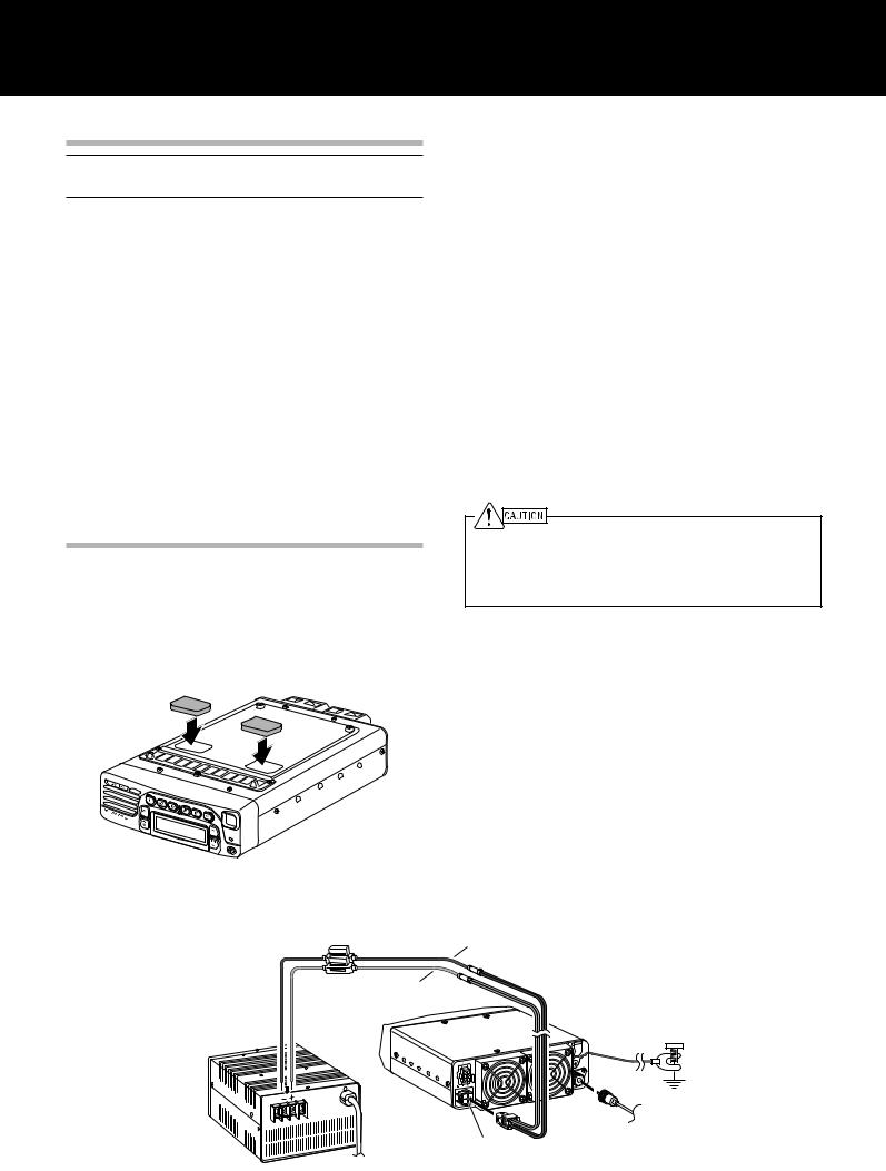
FOOT PADS
A set of foot pads are provided so that you can protect the surface of your desk/table/shelf from scratching. Apply the foot pads to the base of the transceiver.
ANTENNA CONNECTION
For best performance:
•Use a properly adjusted, good-quality 50 Ω antenna.
•Use a good-quality 50 Ω coaxial cable and connector.
•Match the impedance of the coaxial cable and antenna so that the SWR is 1.5:1 or less.
•Ensure that all connections are clean and tight.
The transceiver’s protection circuit will activate if the SWR is greater than 2.5:1, but do not rely on protection to compensate for a poorly functioning antenna system. High SWR will cause the transmit output to drop, and may lead to radio frequency interference with consumer products such as stereo receivers and televisions. You may even interfere with your own transceiver. Reports that your signal is garbled or distorted, especially at peak modulation, may indicate that your antenna system is not transmitting efficiently.
Transmitting without first connecting an antenna or other matched load may damage the transceiver. Always connect the antenna to the transceiver before transmitting.
Use a lightning arrestor to prevent fire, electric shock, or damage to the transceiver.
GROUND CONNECTION
•A good DC ground is required to prevent such dangers as electric shock.
•A good RF ground is required for superior communcations, against which the antenna system can operate.
Both of these conditions can be met by providing a good earth ground for your station. Bury one or more ground rods or a large copper plate under the ground, and connect this to the transceiver GND terminal. Use heavy gauge wire or a copper strap, cut as short as possible, for the connection. Ensure that all connections are clean and tight.
 Fuse (25 A) Black (—)
Red (+)
DC Power supply |
Earth ground |
|
(20.5 A or more) |
||
|
||
|
To antenna |
|
|
DC 13.6 V |
Base Station Installation
1
DC POWER SUPPLY CONNECTION
In order to use this transceiver as a base station, you will need a separate 13.6 V DC power supply with a current capacity of 20.5 A or higher (purchased separately).
Do not directly connect the transceiver to an AC outlet.
Do not substitute the supplied DC power cable with a cable with smaller gauge wires.
Before connecting the DC power supply to the transceiver, be sure to switch the DC power supply OFF.
Do not plug the DC power supply into an AC outlet until you make all connections.
1Connect the supplied DC power cable to the regulated DC power supply and check that the polarities are correct (Red: positive, Black: negative).
2Connect the connectorized end of the DC power cable to the DC 13.6 V powerconnector on the rear of the transceiver.
•Press the DC power cable connector firmly into the connector on the radiotelephone until the locking tab clicks.
■REPLACING FUSES
If the fuse blows, determine the cause then correct the problem. After the problem is resolved, only then replace the fuse. If newly installed fuses continue to blow, disconnect the power plug and contact your dealer for assistance.
Following are the ratings for fuses used with this transceiver:
Transceiver: 4 A (for KAT-1 antenna tuner) DC cable: 25 A
When replacing any fuse, be sure to replace it with a fuse of the same value. Never replace a fuse with a fuse that has a higher value.
Replace blown fuses only after investigating and correcting the cause of the failed fuse.
MOBILE INSTALLATION
Various electronic equipment in your vehicle may malfunction if they are not properly protected from the radio frequency energy which is present while transmitting. Electronic fuel injection, anti-skid braking, and cruise control systems are typical examples of equipment that may malfunction. If your vehicle contains such equipment, consult the dealer for the make of vehicle and enlist his/her aid in determining if they will perform normally while transmitting.
Note: The following preparation instructions are for use by your KENWOOD dealer, an authorized KENWOOD service facility, or the factory.
INSTALLING THE TRANSCEIVER
For passenger safety, install the transceiver securely using an optional mounting bracket so the transceiver will not break loose in the event of a collision.
1Mark the position of the holes in the dash by using the mounting bracket as a template. Drill the holes, then attach the mounting bracket using self-tapping screws supplied with the bracket.
•Be sure to mount the transceiver in a location where the controls are within easy reach of the user and where there is sufficient space at the rear of the transceiver for cable connections.
2Connect the antenna and the supplied power cable to the transceiver {page 3}.
3Slide the transceiver into the mounting bracket and secure it.
4Mount the microphone hanger in a location where it will be within easy reach of the user.
•The microphone and microphone cable should be mounted in a place where they will not interfere with the safe operation of the vehicle.
ANTENNA CONNECTION
For best performance:
•Use a properly adjusted, good-quality 50 Ω antenna.
•Use a good-quality 50 Ω coaxial cable and connector.
Coupling the antenna to the transceiver via feed lines having an impedance other than 50 Ω reduces the efficiency of the antenna system and can cause interference to nearby broadcast television receivers, radio receivers, and other electronic equipment.
Transmitting without first connecting an antenna or other matched load may damage the transceiver. Always connect the antenna to the transceiver before transmitting.
2
GROUND CONNECTION
•A high-quality ground installation significantly improves the performance of a mobile antenna.
Securely connect a low-resistance ground strap (or large gauge copper wire if unavailable) from the transceiver GND terminal to the vehicle chassis. Clean paint or dirt from the vehicle connection point to expose bare metal before connecting the ground.
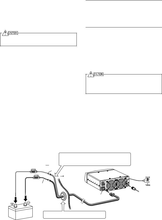
DC POWER CABLE CONNECTION
The transceiver operates in 12 V negative ground systems only!
Check the battery polarity and voltage of the vehicle before installing the transceiver.
1Check for an existing hole, conveniently located in the firewall, where the power cable can be passed through. If no hole exists, use a circle cutter to drill the firewall, then install a rubber grommet.
2Run the two power cable leads through the firewall and into the engine compartment, from the passenger compartment.
3Connect the red lead to the positive (+) battery terminal and the black lead to the negative (–) battery terminal.
•Use the full length of the cable without cutting off any excess; in particular, never remove the fuse holders.
•To prevent the risk of short circuits, disconnect other wiring from the negative (–) battery terminal before connecting the transceiver. Reconnect the wiring after connecting the transceiver to the battery.
•Locate the fuse as close to the battery as possible.
4Coil and secure the surplus cable with a retaining band.
•Be sure to leave enough slack in the cables so the transceiver can be removed for servicing while keeping the power applied.
•Ensure that the cable is isolated from heat and moisture. If necessary, wrap heat-resistant tape around the fuse holder to protect it from moisture.
•If using a noise filter, it should be installed with an insulator to prevent it from touching metal on the vehicle.
5Connect the DC power cable to the rear of the transceiver.
•Press the connectors firmly together until the locking tab clicks.
Note:
We do not recommend using the cigarette lighter socket, as some cigarette lighter sockets introduce an unacceptable voltage drop.
If you use the transceiver for a long period when the vehicle battery is not fully charged or when the engine is OFF, the battery may become discharged and will not have sufficient reserves to start the vehicle. Avoid using the transceiver under these conditions.
■REPLACING FUSES
If the fuse blows, determine the cause then correct the problem. After the problem is resolved, only then replace the fuse. If newly installed fuses continue to blow, disconnect the power plug and contact your dealer for assistance.
Following are the ratings for fuses used with this transceiver:
Transceiver: 4 A (for KAT-1 antenna tuner) DC cable: 25 A
When replacing any fuse, be sure to replace it with a fuse of the same value. Never replace a fuse with a fuse that has a higher value.
Replace blown fuses only after investigating and correcting the cause of the failed fuse.
Place the DC cable securely within the wall of the engine compartment. Ensure that the cable does not come into contact with excessive heat, vapor, and/or water.
Engine compartment 
Red (+)
Passenger compartment
Black (–) |
Vehicle |
|
chassis |
||
|
 To antenna
DC 13.6V
12 |
V battery |
|
Use a rubber or plastic grommet so that the cable does not directly touch the vehicle chassis.
Mobile Installation
3

GETTING ACQUAINTED
FRONT PANEL
q w e |
r |
t |
y |
u |
i |
o |
!0 |
!1 !2 !3 |
q  (Power) switch
Press to switch the transceiver power ON. Press again to switch the power OFF.
wTransmit/ Busy/ Call indicator
Lights red while transmitting and green while receiving a signal. Flashes orange during selcall.
eVOL /
/ keys
keys
Press the key to increase the volume and the
 key to decrease the volume.
rDisplay
Refer to page 5.
tCH /
/ keys
keys
Press the key to increase the channel number and the
 key to decrease the channel number.
yInternal Speaker
Audio is heard from this speaker if no external speaker is connected.
uMicrophone jack
Connect an optional microphone to this jack.
i key
key
Press to activate its programmable function {page 7}. The default setting is Antenna Tuner.
oA key
Press to activate its programmable function {page 7}. The default setting is Squelch Level.
!0B key
Press to activate its programmable function {page 7}. The default setting is Scan.
!1<C key
Press to activate its programmable function {page 7}. The default setting is Clarifier.
!2D> key
Press to activate its programmable function {page 7}. The default setting is Mode.
!3■ key
Press to activate its programmable function {page 7}. The default setting is Menu.
REAR PANEL
q |
w e |
|||||
|
|
|
|
|
|
|
|
|
|
|
|
|
|
|
|
|
|
|
|
|
r |
t |
4
 Loading...