


TK-7185E

TK-7185
INSTRUCTION MANUAL
VHF FM TRANSCEIVER
© B62-2105-00 (E)
09 08 07 06 05 04 03 02 01 00
NOTIFICATION
This equipment complies with the essential requirements of
Directive 1999/5/EC.
The use of the warning symbol means the equipment is subject
to restrictions of use in certain countries.
This equipment requires a licence and is intended for use in the
countries as below.
AT BE DK FI FR DE GR IS
IE IT LI LU NL NO PT ES
SE CH GB CY CZ EE HU LV
LT MT PL SK SI BG RO
ISO3166


i
THANK YOU!
We are grateful you chose
Kenwood
for your personal mobile applications. We
believe this easy-to-use transceiver will provide dependable communications to
keep personnel operating at peak efficiency.
Kenwood
transceivers incorporate the latest in advanced technology. As a
result, we feel strongly that you will be pleased with the quality and features of this
product.
NOTICES TO THE USER
◆
Government law prohibits the operation of unlicensed transmitters within the territories under
government control.
◆
Illegal operation is punishable by fine and/or imprisonment.
◆
Refer service to qualified technicians only.
SAFETY:
It is important that the operator is aware of, and understands, hazards
common to the operation of any transceiver.
◆
EXPLOSIVE ATMOSPHERES (GASES, DUST, FUMES, etc.)
Turn OFF your transceiver while taking on fuel or while parked in gasoline service stations. Do
not carry spare fuel containers in the trunk of your vehicle if your transceiver is mounted in the
trunk area.
◆
INJURY FROM RADIO FREQUENCY TRANSMISSIONS
Do not operate your transceiver when somebody is either standing near to or touching the
antenna, to avoid the possibility of radio frequency burns or related physical injury.
◆
DYNAMITE BLASTING CAPS
Operating the transceiver within 500 feet (150 m) of dynamite blasting caps may cause them
to explode. Turn OFF your transceiver when in an area where blasting is in progress, or where
“TURN OFF TWO-WAY RADIO” signs have been posted. If you are transporting blasting caps
in your vehicle, make sure they are carried in a closed metal box with a padded interior. Do not
transmit while the caps are being placed into or removed from the container.
Information on Disposal of Old Electrical and Electronic Equipment and Batteries (applicable
for EU countries that have adopted separate waste collection systems)
Products and batteries with the symbol (crossed-out wheeled bin) cannot be disposed
as household waste.
Old electrical and electronic equipment and batteries should be recycled at a facility
capable of handling these items and their waste byproducts.
Contact your local authority for details in locating a recycle facility nearest to you.
Proper recycling and waste disposal will help conserve resources whilst preventing
detrimental effects on our health and the environment.

ii
PRECAUTIONS
Observe the following precautions to prevent fire, personal injury, and transceiver
damage.
• Do not attempt to configure the transceiver while driving; it is too dangerous.
• Do not disassemble or modify the transceiver for any reason.
• Do not expose the transceiver to long periods of direct sunlight, nor place it near heating
appliances.
• If an abnormal odor or smoke is detected coming from the transceiver, switch the
transceiver power off immediately, and contact your
Kenwood
dealer.
• Use of the transceiver while you are driving may be against traffic laws. Please check
and observe the vehicle regulations in your area.
• Do not use options not specified by
Kenwood
.
◆
The transceiver operates in 12 V negative ground systems only! Check the battery polarity and
voltage of the vehicle before installing the transceiver.
◆
Use only the supplied DC power cable or a
Kenwood
optional DC power cable.
◆
Do not cut and/or remove the fuse holder on the DC power cable.
For passenger safety, install the transceiver securely using the supplied mounting bracket and
screw set so the transceiver will not break loose in the event of a collision.

iii
CONTENTS
UNPACKING AND CHECKING EQUIPMENT ....................................1
S
upplied AcceSSorieS .......................................................................1
PREPARATION ...................................................................................2
T
oolS required ................................................................................2
p
ower cAble connecTion .................................................................2
i
nSTAlling The TrAnSceiver ...............................................................3
GETTING ACQUAINTED .....................................................................4
F
ronT pAnel .....................................................................................4
reAr pAnel ......................................................................................5
BASIC OPERATIONS ..........................................................................6
SwiTching power on/ oFF ..............................................................6
AdjuSTing The volume .......................................................................6
TRUNKING MODE ...............................................................................7
Key FuncTionS ..................................................................................7
diSplAy .............................................................................................8
progrAmmAble FuncTionS .................................................................9
SeArching For A conTrol chAnnel ...................................................9
voice cAllS ....................................................................................10
STATuS cAllS .................................................................................11
dATA cAllS ....................................................................................11
cAll diSplAyS .................................................................................12
viewing The STAcK ..........................................................................12
cAll diverTing ...............................................................................13
KeypAd enTry .................................................................................14
emergency cAllS ...........................................................................14
public AddreSS (pA) ......................................................................14
horn AlerT ....................................................................................14
AuxiliAry porT ...............................................................................15
gpS reporT ...................................................................................15
home AddreSS ................................................................................15
SiTe locK .......................................................................................15
Sub-lcd diSplAy ...........................................................................15
SwiTching To convenTionAl mode ...................................................15

iv
CONVENTIONAL MODE ...................................................................16
K
ey FuncTionS ................................................................................16
diSplAy ...........................................................................................17
p
rogrAmmAble FuncTionS ...............................................................18
convenTionAl operATion .................................................................18
ScAnning ........................................................................................18
Squelch oFF...................................................................................19
emergency (TrunKing) ....................................................................19
quieT TAlK (qT)/ digiTAl quieT TAlK (dqT) ...................................19
Time-ouT Timer (ToT) .....................................................................20
buSy chAnnel locKouT (bcl) ........................................................20
SwiTching To TrunKing mode ..........................................................20
ADVANCED & BACKGROUND OPERATIONS ...............................21
ScrAmbler ......................................................................................21
dTmF (duAl Tone mulTi Frequency) cAllS ...................................21
gpS poSiTion diSplAy ....................................................................21
lcd brighTneSS .............................................................................21
clocK .............................................................................................22
SignAl STrengTh indicATor .............................................................22
VGS-1 OPTIONAL VOICE GUIDE & STORAGE UNIT .....................23
voice recorder ..............................................................................23
voice guide ....................................................................................24
APPENDIX .........................................................................................25
1
UNPACKING AND CHECKING EQUIPMENT
Note:
The following unpacking instructions are for use by your
Kenwood
dealer, an authorized
Kenwood
service facility, or the factory.
Carefully unpack the transceiver. We recommend that you identify the items
listed in the following table before discarding the packing material. If any items
are missing or have been damaged during shipment, file a claim with the carrier
immediately.
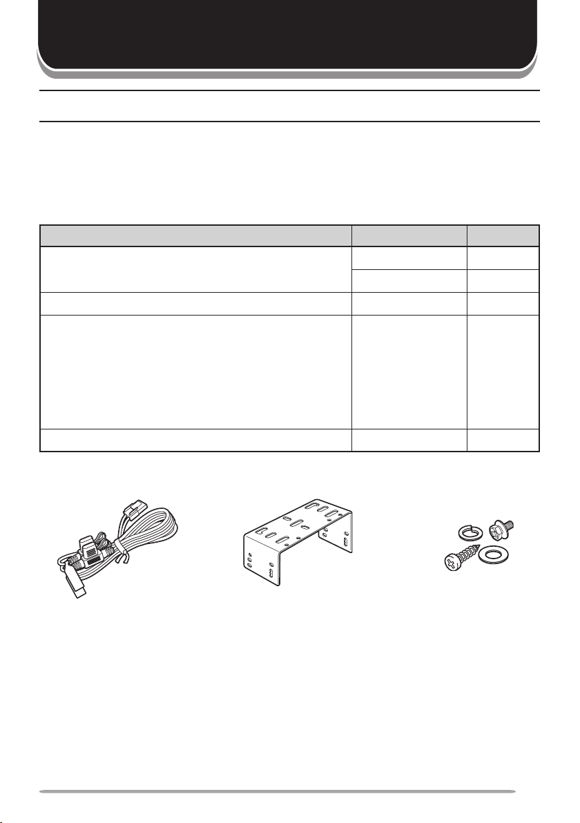
Supplied AcceSSorieS
Item Part Number Quantity
DC power cable E30-7523-XX 1
• Fuse (15 A)
F52-0024-XX 2
Mounting bracket J29-0726-XX 1
Screw set
N99-2039-XX 1
• Self-tapping screw (4 pieces)
• Hex-headed screw with washer (4 pieces)
• Spring washer (4 pieces)
• Flat washer (4 pieces)
Instruction manual B62-2105-XX 1
DC power cable
(with fuses)
Mounting bracket Screw set

2
Various electronic equipment in your vehicle may malfunction if they are not properly protected
from the radio frequency energy which is present while transmitting. Electronic fuel injection, anti-
skid braking, and cruise control systems are typical examples of equipment that may malfunction. If
your vehicle contains such equipment, consult the dealer for the make of vehicle and enlist his/her
aid in determining if they will perform normally while transmitting.
Note
: The following preparation instructions are for use by your
Kenwood
dealer, an authorized
Kenwood
service facility, or the factory.
ToolS required
Note
: Before installing the transceiver, always check how far the mounting screws will extend
below the mounting surface. When drilling mounting holes, be careful not to damage vehicle wiring
or parts.
The following tools are required for installing the transceiver:
• 1/4 inch (6 mm) or larger electric drill
• 5/32 inch (4.2 mm) drill bit for the self-tapping screws
• Circle cutters
power cAble connecTion
◆
The transceiver operates in
12 V
negative ground systems only! Check the battery polarity and
voltage of the vehicle before installing the transceiver.
◆
Do not cut and/or remove the fuse holder on the DC power cable.
1
Check for an existing hole, conveniently located in the firewall, where the
power cable can be passed through. If no hole exists, use a circle cutter to
drill the firewall, then install a rubber grommet.
2
Run the two power cable leads through the firewall and into the engine
compartment, from the passenger compartment.
3
Connect the red lead to the positive (+) battery terminal and the black lead to
the negative (–) battery terminal.
• Locate the fuse as close to the battery as possible.
4
Coil and secure the surplus cable with a retaining band.
• Be sure to leave enough slack in the cables so the transceiver can be removed for
servicing while keeping the power applied.
PREPARATION
3
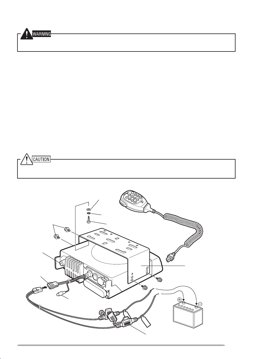
inSTAlling The TrAnSceiver
For passenger safety, install the transceiver securely using the supplied mounting bracket and
screw set so the transceiver will not break loose in the event of a collision.
1
Mark the position of the holes in the dash by using the mounting bracket as a
template. Drill the holes, then attach the mounting bracket using the supplied
self-tapping screws.
• Be sure to mount the transceiver in a location where the controls are within easy
reach of the user and where there is sufficient space at the rear of the transceiver for
cable connections.
2
Connect the antenna and the supplied power cable to the transceiver.
3
Slide the transceiver into the mounting bracket and secure it using the supplied
hex-headed screws.
4
Mount the optional microphone hanger in a location where it will be within easy
reach of the user.
• The optional microphone and microphone cable should be mounted in a place where
they will not interfere with the safe operation of the vehicle.
When replacing the fuse in the DC power cable, be sure to replace it with a fuse of the same value.
Never replace a fuse with a fuse that has a higher value.
Hex-headed
screws
DC power
cable
Mounting bracket
Antenna
connector
Power input
connector
Fuse
Black (–)
cable
Red (+)
cable
12 V vehicle
battery
Self-tapping screw
Spring washer
Flat washer
Ignition
sense cable
Optional microphone
4
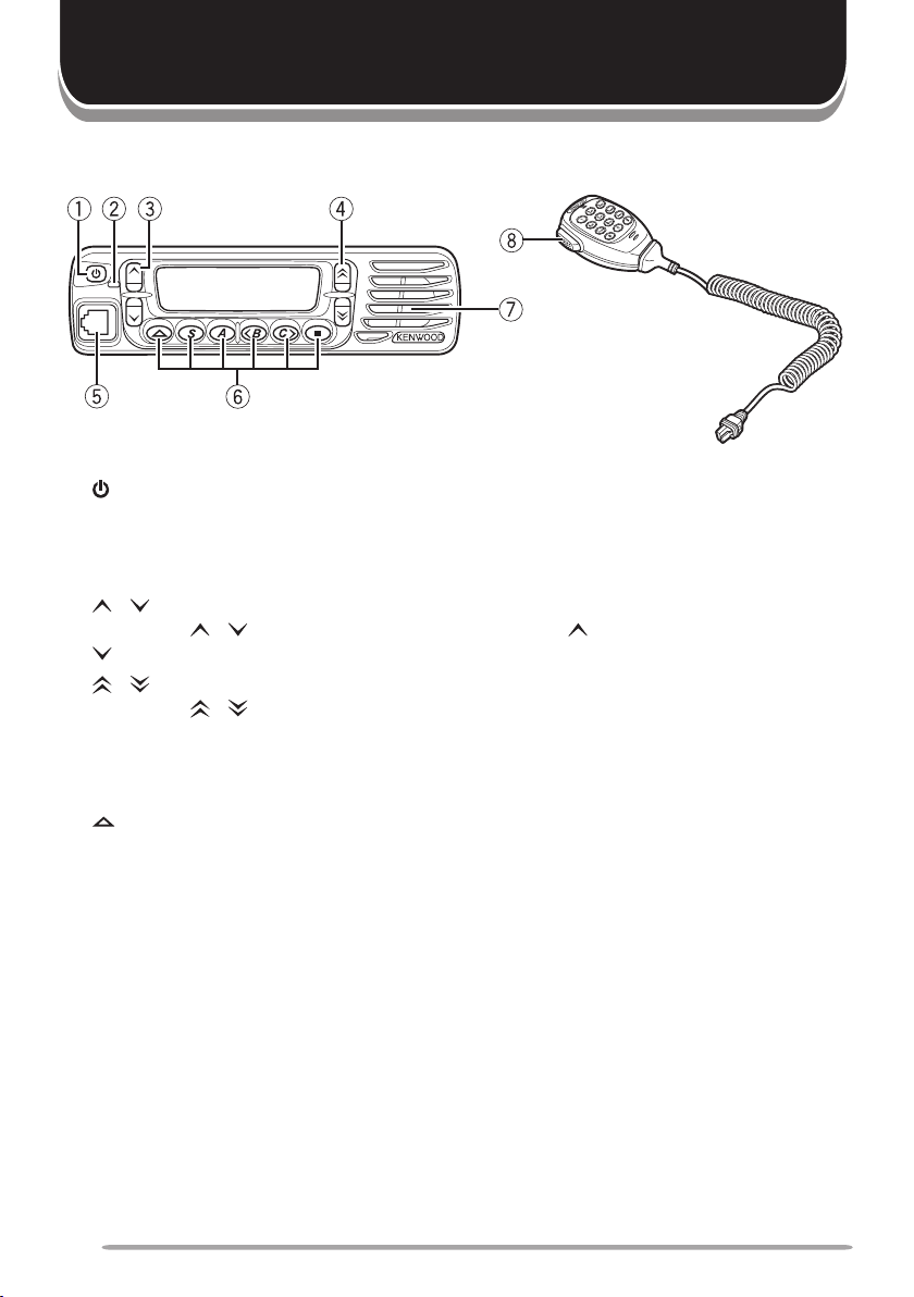
GETTING ACQUAINTED
FronT pAnel
q
(Power) switch
Press to switch the transceiver ON. Press again to switch the transceiver OFF.
w
Transmit/ Busy indicator
This LED lights red while transmitting and green while receiving a call.
e
/ keys
Press the / keys to adjust the volume level. increases the volume and
decreases it.
r
/ keys
Press the
/ keys to select your desired channel/ call address (voice calls)
or status (status calls).
t
Microphone jack
Insert the microphone plug into this jack.
y
, S, A, <B, C>, and
■
keys
Press to activate their programmable functions*.
u
Speaker
Internal speaker.
i
PTT (Push-to-Talk) switch
Press and hold this switch, then speak into the microphone to call a station.
* Programmable functions vary, depending on the transceiver operating mode. Refer to
Trunking Mode {page 7} or Conventional Mode {page 16} for applicable functions.
 Loading...