


INSTRUCTION MANUAL
144 MHz FM TRANSCEIVER
TH-K20A
TH-K20E
430 MHz FM TRANSCEIVER
TH-K40A
TH-K40E
NOTIFICATION
This equipment complies with the essential requirements of Directive 1999/5/EC.
The use of the warning symbol  means the equipment is subject to restrictions of use in certain countries.
This equipment requires a licence and is intended for use in the countries as below.
AT |
BE |
DK |
FI |
FR |
DE |
GR |
IS |
|
IE |
IT |
LI |
LU |
NL |
NO |
PT |
ES |
|
SE |
CH |
GB |
CY |
CZ |
EE |
HU |
LV |
|
LT |
MT |
PL |
SK |
SI |
BG |
RO |
|
|
|
|
|
|
|
|
|
ISO3166 |
|
© B62-2365-00 (K, E, M)
09 08 07 06 05 04 03 02 01 00

THANK YOU
We are grateful you decided to purchase this KENWOOD FM transceiver. KENWOOD always provides Amateur Radio products which surprise and excite serious hobbyists. This transceiver is no exception. KENWOOD believes that this product will satisfy your requirements for voice communication.
MARKET TYPE CODES
K: The Americas E: Europe
M: General
The market type code is printed on the bar-code label of the carton box.
WRITING CONVENTIONS FOLLOWED IN THIS MANUAL
The writing conventions described below have been followed to simplify instructions and avoid unnecessary repetition.
Instruction |
Action |
|
|
|
|
Press [KEY]. |
Momentarily press KEY. |
|
|
|
|
Press [KEY] (1s). |
Press and hold KEY for 1 second or longer. |
|
|
|
|
Press [KEY1], [KEY2]. |
Press KEY1 momentarily, release KEY1, then press |
|
KEY2. |
||
|
||
|
|
|
Press [F] - [KEY]. |
Press the F key to enter Function mode, then press |
|
KEY to access its secondary function. |
||
|
||
|
|
|
Press [KEY] + Power ON. |
With the transceiver power OFF, press and hold |
|
KEY while turning the transceiver power ON. |
||
|
||
|
|
Information on Disposal of Old Electrical and Electronic Equipment and Batteries (applicable for EU countries that have adopted separate waste collection systems)
Products and batteries with the symbol (crossed-out wheeled bin) cannot be disposed as household waste.
Old electrical and electronic equipment and batteries should be recycled at a facility capable
of handling these items and their waste byproducts.
Contact your local authority for details in locating a recycle facility nearest to you. Proper recycling and waste disposal will help conserve resources whilst preventing detrimental effects on our health and the environment.
Notice: The sign "Pb" below the symbol for batteries indicates that this battery contains lead.
Firmware Copyrights
The title to and ownership of copyrights for firmware embedded in KENWOOD product memories are reserved for JVC KENWOOD Corporation.
WHEN CONDENSATION OCCURS INSIDE THE TRANSCEIVER
Condensation may occur inside the transceiver in such a case where the room is warmed using
a heater on cold days or where the transceiver is quickly moved from a cold room to a warm room. When condensation occurs, the microcomputer and/or the transmit/receive circuits may become unstable, resulting in transceiver malfunction. If this happens, turn OFF the transceiver and just wait for a while. When the condensation droplets disappear, the transceiver will function normally.

NOTICES TO THE USER
One or more of the following statements may be applicable:
FCC WARNING
This equipment generates or uses radio frequency energy. Changes or modifications to this equipment may cause harmful interference unless the modifications are expressly approved in the instruction manual. The user could lose the authority to operate this equipment if an unauthorized change or modification is made.
INFORMATION TO THE DIGITAL DEVICE USER REQUIRED BY THE FCC
This equipment has been tested and found to comply with the limits for a Class B digital device, pursuant to Part 15 of the FCC Rules. These limits are designed to provide reasonable protection against harmful interference in a residential installation.
This equipment generates, uses and can generate radio frequency energy and, if not
installed and used in accordance with the instructions, may cause harmful interference to radio communications. However, there is no guarantee that the interference will not occur in a particular installation. If this equipment does cause harmful interference to radio or television reception, which can be determined by turning the equipment off and on, the user is encouraged to try to correct the interference by one or more of the following measures:
•Reorient or relocate the receiving antenna.
•Increase the separation between the equipment and receiver.
•Connect the equipment to an outlet on a circuit different from that to which the receiver is connected.
•Consult the dealer for technical assistance.
ATTENTION: (USA only)
The RBRC Recycle seal found on KENWOOD lithium-ion (Li-ion) battery packs indicates KENWOOD’s voluntary participation in an industry program to collect and recycle Li-ion batteries after their operating life has expired. The RBRC program is an alternative to disposing Li-ion batteries with your regular refuse or in municipal waste streams, which is illegal in some areas.
For information on Li-ion battery recycling in your area, call (toll free) 1-800-8-BATTERY (1-800-822-8837).
KENWOOD’s involvement in this program is part of our commitment to preserve our environment and conserve our natural resources.
This device complies with Industry Canada licence-exempt RSS standard(s). Operation is subject to the following two conditions: (1) this device may not cause interference, and (2) this device must accept any interference, including interference that may cause undesired operation of the device.
i
PRECAUTIONS
•Do not charge the transceiver and battery pack when they are wet.
•Ensure that there are no metallic items located between the transceiver and the battery pack.
•Do not use options not specified by KENWOOD.
•If the die-cast chassis or other transceiver part is damaged, do not touch the damaged parts.
•If a headset or headphone is connected to the transceiver, reduce the transceiver volume. Pay attention to the volume level when turning the squelch off.
•Do not place the microphone cable around your neck while near machinery that may catch the cable.
•Do not place the transceiver on unstable surfaces.
•Ensure that the end of the antenna does not touch your eyes.
•When the transceiver is used for transmission for many hours, the radiator and chassis will become hot. Do not touch these locations when replacing the battery pack.
•Do not immerse the transceiver in water.
•Always switch the transceiver power off before installing optional accessories.
•For safety reasons, we recommend that the battery charger be connected to an easily accessible AC socket.
Turn the transceiver power off in the following locations:
•In explosive atmospheres (inflammable gas, dust particles, metallic powders, grain powders, etc.).
•While taking on fuel or while parked at gasoline service stations.
•Near explosives or blasting sites.
•In aircraft. (Any use of the transceiver must follow the instructions and regulations provided by the airline crew.)
•Where restrictions or warnings are posted regarding the use of radio devices, including but not limited to medical facilities.
•Near persons using pacemakers.
•Do not disassemble or modify the transceiver for any reason.
•Do not place the transceiver on or near airbag equipment while the vehicle is running. When the airbag inflates, the transceiver may be ejected and strike the driver or passengers.
•Do not transmit while touching the antenna terminal or if any metallic parts are exposed from the antenna covering. Transmitting at such a time may result in a high-frequency burn.
•If an abnormal odor or smoke is detected coming from the transceiver, switch the transceiver power off immediately, remove the battery pack from the transceiver, and contact your KENWOOD dealer.
•Use of the transceiver while you are driving may be against traffic laws. Please check and observe the vehicle regulations in your area.
•Do not expose the transceiver to extremely hot or cold conditions.
•Do not carry the battery pack (or battery case) with metal objects, as they may short the battery terminals.
ii

•Danger of explosion if the battery is incorrectly replaced; replace only with the same type.
•When operating the transceiver in areas where the air is dry, it is easy to build up an electric charge (static electricity). When using an earphone accessory in such conditions, it is possible for the transceiver to send an electric shock through the earphone and to your ear. We recommend you use only a speaker/microphone in these conditions, to avoid electric shocks.
•When attaching a commercial strap to the transceiver, ensure that the strap is durable. In addition, do not swing the transceiver around by the strap; you may inadvertently strike and injure another person with the transceiver.
Information concerning the battery pack:
The battery pack includes flammable objects such as organic solvent. Mishandling may cause the battery to rupture producing flames or extreme heat, deteriorate, or cause other forms of damage to the battery. Please observe the following prohibitive matters.
•Do not disassemble or reconstruct battery!
The battery pack has a safety function and protection circuit to avoid danger. If they suffer serious damage, the battery may generate heat or smoke, rupture, or burst into flame.
•Do not short-circuit the battery!
Do not join the + and – terminals using any form of metal (such as a paper clip or wire). Do not carry or store the battery pack in containers holding metal objects (such as wires, chain-necklace or hairpins). If the battery pack is short-circuited, excessive current will flow and the battery may generate heat or smoke, rupture, or burst into flame. It will also cause metal objects to heat up.
•Do not incinerate or apply heat to the battery!
If the insulator is melted, the gas release vent or safety function is damaged, or the electrolyte is ignited, the battery may generate heat or smoke, rupture, or burst into flame.
•Do not leave the battery near fire, stoves, or other heat generators (areas reaching over 80°C/ 176°F)!
If the polymer separator is melted due to high temperature, an internal short-circuit may occur in the individual cells and the battery may generate heat or smoke, rupture, or burst into flame.
•Avoid immersing the battery in water or getting it wet by other means!
If the battery becomes wet, wipe it off with a dry towel before use. If the battery’s protection circuit is damaged, the battery may charge at extreme current (or voltage) and an abnormal chemical reaction may occur. The battery may generate heat or smoke, rupture, or burst into flame.
•Do not charge the battery near fire or under direct sunlight!
If the battery’s protection circuit is damaged, the battery may charge at extreme current (or voltage) and an abnormal chemical reaction may occur. The battery may generate heat or smoke, rupture, or burst into flame.
•Use only the specified charger and observe charging requirements!
If the battery is charged in unspecified conditions (under high temperature over the regulated value, excessive high voltage or current over regulated value, or with a remodeled charger), it may overcharge or an abnormal chemical reaction may occur. The battery may generate heat or smoke, rupture, or burst into flame.
iii
•Do not pierce the battery with any object, strike it with an instrument, or step on it!
This may break or deform the battery, causing a short-circuit. The battery may generate heat or smoke, rupture, or burst into flame.
•Do not jar or throw the battery!
An impact may cause the battery to leak, generate heat or smoke, rupture, and/or burst into flame. If the battery’s protection circuit is damaged, the battery may charge at an abnormal current (or voltage), and an abnormal chemical reaction may occur. The battery may generate heat or smoke, rupture, or burst into flame.
•Do not use the battery pack if it is damaged in any way!
The battery may generate heat or smoke, rupture, or burst into flame.
•Do not solder directly onto the battery!
If the insulator is melted or the gas release vent or safety function is damaged, the battery may generate heat or smoke, rupture, or burst into flame.
•Do not reverse the battery polarity (and terminals)!
When charging a reversed battery, an abnormal chemical reaction may occur. In some cases, an unexpected large amount of current may flow upon discharging. The battery may generate heat or smoke, rupture, or burst into flame.
•Do not reverse-charge or reverse-connect the battery!
The battery pack has positive and negative poles. If the battery pack does not smoothly connect with a charger or operating equipment, do not force it; check the polarity of the battery. If the battery pack is reverse-connected to the charger, it will be reverse-charged and an abnormal chemical reaction may occur. The battery may generate heat or smoke, rupture, or burst into flame.
•Do not touch a ruptured and leaking battery!
If the electrolyte liquid from the battery gets into your eyes, wash your eyes with fresh water as soon as possible, without rubbing your eyes. Go to the hospital immediately. If left untreated, it may cause eye-problems.
•Do not charge the battery for longer than the specified time!
If the battery pack has not finished charging even after the regulated time has passed, stop it. The battery may generate heat or smoke, rupture, or burst into flame.
•Do not place the battery pack into a microwave or high pressure container!
The battery may generate heat or smoke, rupture, or burst into flame.
•Keep ruptured and leaking battery packs away from fire!
If the battery pack is leaking (or the battery emits a bad odor), immediately remove it from flammable areas. Electrolyte leaking from battery can easily catch on fire and may cause the battery to generate smoke or burst into flame.
•Do not use an abnormal battery!
If the battery pack emits a bad odor, appears to have different coloring, is deformed, or seems abnormal for any other reason, remove it from the charger or operating equipment and do not use it. The battery may generate heat or smoke, rupture, or burst into flame.
iv

CONTENTS
PREPARATION ................................................................................................... |
1 |
SUPPLIED ACCESSORIES ........................................................................... |
1 |
INSTALLING THE ANTENNA......................................................................... |
1 |
INSTALLING THE BATTERY PACK .............................................................. |
2 |
INSTALLING THE BELT CLIP........................................................................ |
2 |
CHARGING THE BATTERY PACK................................................................ |
3 |
CONNECTING TO THE PC............................................................................ |
5 |
GETTING ACQUAINTED..................................................................................... |
6 |
PANEL ............................................................................................................ |
6 |
DISPLAY......................................................................................................... |
8 |
BASIC OPERATION.......................................................................................... |
10 |
SWITCHING THE POWER ON/OFF............................................................ |
10 |
ADJUSTING THE VOLUME ......................................................................... |
10 |
ADJUSTING THE SQUELCH....................................................................... |
10 |
SELECTING A FREQUENCY....................................................................... |
11 |
TRANSMITTING/ RECEIVING ..................................................................... |
11 |
DIRECT FREQUENCY ENTRY.................................................................... |
12 |
SELECTING AN OUTPUT POWER ............................................................. |
12 |
BACKLIGHT ................................................................................................. |
13 |
MONITOR..................................................................................................... |
13 |
LOCK FUNCTION ........................................................................................ |
14 |
MENU SETUP.................................................................................................... |
15 |
WHAT IS A MENU?...................................................................................... |
15 |
MENU ACCESS ........................................................................................... |
15 |
MENU FUNCTION LIST ............................................................................... |
16 |
MEMORY CHANNELS ...................................................................................... |
18 |
SIMPLEX & REPEATER OR ODD-SPLIT MEMORY CHANNEL?............... |
18 |
STORING SIMPLEX AND STANDARD REPEATER FREQUENCIES ........ |
19 |
STORING ODD-SPLIT REPEATER FREQUENCIES.................................. |
20 |
RECALLING A MEMORY CHANNEL........................................................... |
20 |
NAMING A MEMORY CHANNEL................................................................. |
21 |
MEMORY DISPLAY TYPE ........................................................................... |
22 |
CLEARING A MEMORY CHANNEL............................................................. |
22 |
CALL CHANNEL........................................................................................... |
23 |
MEMORY CHANNEL TRANSFER ............................................................... |
24 |
CHANNEL DISPLAY MODE......................................................................... |
24 |
SCAN ................................................................................................................. |
26 |
BAND SCAN................................................................................................. |
26 |
PROGRAM SCAN ........................................................................................ |
27 |
MEMORY SCAN........................................................................................... |
28 |
CALL SCAN.................................................................................................. |
28 |
PRIORITY SCAN.......................................................................................... |
28 |
MEMORY CHANNEL LOCKOUT ................................................................. |
29 |
SELECTING A SCAN RESUME METHOD .................................................. |
30 |
v

OPERATING THROUGH REPEATERS............................................................ |
31 |
SELECTING AN OFFSET DIRECTION (SHIFT).......................................... |
31 |
SELECTING AN OFFSET FREQUENCY..................................................... |
32 |
TONE FUNCTION ........................................................................................ |
32 |
AUTOMATIC REPEATER OFFSET ............................................................. |
34 |
REVERSE FUNCTION ................................................................................. |
34 |
TRANSMITTING A 1750 Hz TONE .............................................................. |
35 |
SIGNALING........................................................................................................ |
36 |
CTCSS.......................................................................................................... |
36 |
DCS .............................................................................................................. |
37 |
CROSS TONE .............................................................................................. |
39 |
DTMF FUNCTIONS............................................................................................ |
40 |
MANUAL DIALING ....................................................................................... |
40 |
AUTOMATIC DIALER................................................................................... |
40 |
ADJUSTING THE DTMF CODE TRANSMIT SPEED .................................. |
41 |
DTMF TX HOLD ........................................................................................... |
42 |
ADJUSTING THE PAUSE DURATION ........................................................ |
42 |
DTMF LOCK ................................................................................................. |
42 |
AUXILIARY FUNCTIONS .................................................................................. |
43 |
PROGRAMMABLE VFO............................................................................... |
43 |
FREQUENCY STEP SIZE............................................................................ |
44 |
TONE ALERT ............................................................................................... |
44 |
POWER ON MESSAGE ............................................................................... |
45 |
BEEP FUNCTION......................................................................................... |
46 |
LOCK TYPE.................................................................................................. |
46 |
BATTERY SAVER ........................................................................................ |
47 |
APO (AUTO POWER OFF) .......................................................................... |
48 |
NARROW BAND FM OPERATION .............................................................. |
48 |
BEAT SHIFT ................................................................................................. |
49 |
VOX (VOICE-OPERATED TRANSMIT) ....................................................... |
49 |
TIME-OUT TIMER ........................................................................................ |
51 |
BUSY CHANNEL LOCKOUT........................................................................ |
51 |
TX INHIBIT ................................................................................................... |
52 |
MICROPHONE SENSITIVITY ...................................................................... |
52 |
PROGRAMMABLE FUNCTION KEYS......................................................... |
52 |
MICROPHONE KEY LOCK .......................................................................... |
53 |
BATTERY TYPE........................................................................................... |
53 |
WEATHER ALERT (TH-K20A K TYPE ONLY)................................................. |
54 |
WEATHER ALERT ON/ OFF........................................................................ |
54 |
WEATHER CHANNEL.................................................................................. |
54 |
WEATHER CHANNEL SCAN....................................................................... |
54 |
APPENDIX ......................................................................................................... |
55 |
OPTIONAL ACCESSORIES......................................................................... |
55 |
MAINTENANCE............................................................................................ |
55 |
TROUBLESHOOTING.................................................................................. |
56 |
TRANSCEIVER RESET ............................................................................... |
58 |
SPECIFICATIONS........................................................................................ |
59 |
vi

PREPARATION
SUPPLIED ACCESSORIES
After carefully unpacking the transceiver, identify the items listed in the table below. We recommend you keep the box and packaging for shipping.
Item |
Comments |
|
Quantity |
|
|
|
|
|
|||
K type |
E type |
M type |
|||
|
|
||||
|
|
|
|
|
|
Antenna |
|
1 |
1 |
1 |
|
|
|
|
|
|
|
Li-ion battery pack |
KNB-63L |
1 |
1 |
1 |
|
|
|
|
|
|
|
Battery charger |
with AC adapter (KSC-35S) |
1 |
1 |
1 |
|
|
|
|
|
|
|
Belt clip |
KBH-18 |
1 |
1 |
1 |
|
|
|
|
|
|
|
Warranty card |
|
1 |
1 |
− |
|
|
|
|
|
|
|
|
English |
1 |
1 |
1 |
|
|
|
|
|
|
|
|
French |
1 |
1 |
− |
|
|
|
|
|
|
|
|
Spanish |
1 |
1 |
− |
|
|
|
|
|
|
|
Instruction manual |
Italian |
− |
1 |
− |
|
|
|
|
|
||
German |
− |
1 |
− |
||
|
|||||
|
|
|
|
|
|
|
Dutch |
− |
1 |
− |
|
|
|
|
|
|
|
|
Turkish |
− |
1 |
− |
|
|
|
|
|
|
|
|
Chinese |
|
|
1 |
|
|
|
|
|
|
INSTALLING THE ANTENNA
Hold the supplied antenna by its base, then screw it into the connector on the top panel of the transceiver until secure.
Note: The antenna is neither a handle, a key ring retainer, nor a speaker/ microphone attachment point. Using the antenna in these ways may damage the antenna and degrade your transceiver’s performance.
1
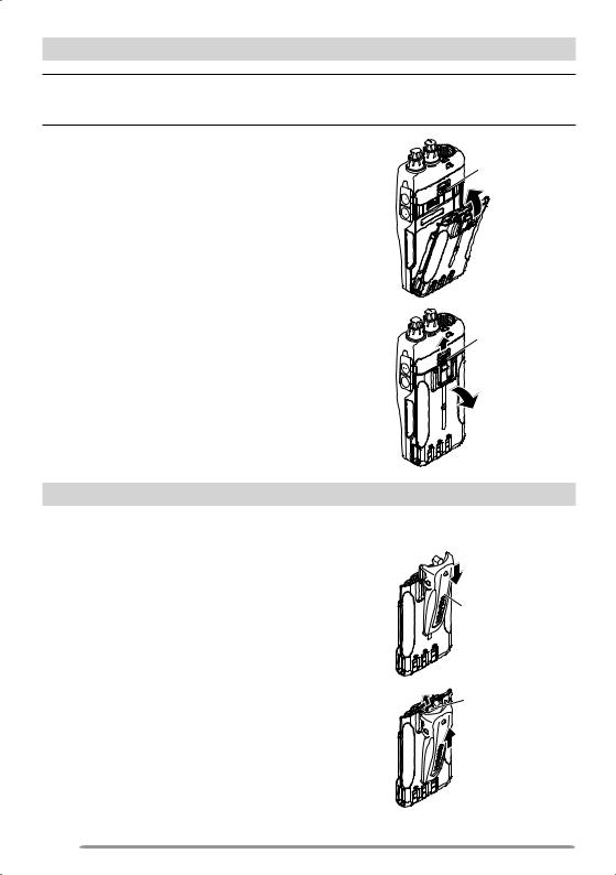
INSTALLING THE BATTERY PACK
Note: Because the battery pack is provided uncharged, you must charge the battery pack before using it with the transceiver. To charge the battery pack, refer to “CHARGING THE BATTERY PACK ” {page 3}.
1 To install the battery pack, align the base of the |
|
|
battery pack with the transceiver, then press |
Lock lever |
|
the battery pack into place until the lock lever is |
||
|
||
secure. |
|
2 To remove the battery pack, push the lock lever |
|
|
up, then pull the battery pack away from the |
Lock lever |
|
transceiver. |
||
|
INSTALLING THE BELT CLIP
If desired, you can install the supplied belt clip to the transceiver.
1 Remove the battery pack, as described above.
2 |
To install the belt clip, align the guides of the |
|
|
belt clip with the grooves on the rear of the |
|
|
battery pack, then slide the belt clip into place |
Belt clip |
|
until the lock lever is secure. |
|
3 |
To remove the belt clip, push the lock lever |
|
|
towards the transceiver while sliding the belt |
Lock lever |
|
clip up. |
|
2
CHARGING THE BATTERY PACK
The battery pack can be charged after it has been installed onto the transceiver. (The battery pack is provided uncharged for safety purposes.)
1Confirm that the transceiver power is OFF.
•While charging the transceiver with a battery pack installed, be sure to turn the transceiver power OFF.
2Plug the AC adapter cable into the jack located on the rear of the charger.
3Plug the AC adapter into an AC outlet.
4Slide a battery pack or a transceiver equipped with a battery pack into the charging slot.
•Make sure the metal contacts of the battery pack mate securely with the charger terminals.
•The indicator lights red and charging starts.
5When charging is completed, the indicator lights green. Remove the battery pack or the transceiver from the charging slot.
•When the charger will not be used for a long time, unplug the AC adapter from the AC outlet.
Charging slot
Indicator 


Note:
Using the transceiver while charging its battery pack will interfere with correct charging.
If the operating time of a battery pack decreases although the battery pack is fully and correctly charged, the battery pack life is over. Replace the battery pack.
The ambient temperature should be from 41°F (5°C) to 104°F (40°C) while charging is in progress.
The charging times provided are obtained when a battery pack discharged to 3 V/cell x 2 is charged at normal temperatures. This charging time varies depending on the degree of discharge and the ambient charging temperature.
This charger may be suitable to charge battery packs not listed herein, due to further technology development.
If the battery pack contacts are not properly mated with the charger terminals, the indicator may blink red or may remain unlit. To resolve this problem, reinsert the battery pack after cleaning the battery pack contacts and the charger terminals.
When using this equipment near a radio or television, you may experience interference with reception.
While charging, do not connect the PC Interface cable to the transceiver.
3

Approximate Charging Times
3 hours
Charger Status Table
Indicator color |
Meaning |
|
|
|
|
Red |
A battery pack is in the charging slot and charging has |
|
started. |
||
|
||
|
The battery pack is defective or the battery pack |
|
Blinking Red |
contacts are not properly mated with those of the |
|
|
charger. |
|
Green |
Charging is completed; remove the battery pack or the |
|
transceiver from the charging slot. |
||
|
||
Alternates flashing green |
The temperature of the battery pack has not satisfied |
|
the charging start temperature. Remove the battery |
||
and orange |
pack from the charger and wait until it reaches a normal |
|
|
temperature before charging it again. |
|
|
|
Battery Life
Before you operate the transceiver outside, using a battery pack, it is important to know how long the battery pack will last. The operating times listed in the table below are measured under the following cyclic conditions:
TX: 6 seconds, RX: 6 seconds, Stand-by: 48 seconds (Battery Saver: ON)
We recommend you carry extra battery packs with you, in case the battery pack becomes depleted.
Battery Type |
Output Power |
Operating Time/ Hours (Approx.) |
||
|
|
|
|
|
|
High |
6 (KNB-63L) |
|
8 (KNB-65L) |
KNB-63L/ KNB-65L |
|
|
|
|
Medium |
8.5 (KNB-63L) |
|
11.5 (KNB-65L) |
|
(7.4 V) |
|
|||
|
|
|
|
|
Low |
10.5 (KNB-63L) |
|
14 (KNB-65L) |
|
|
|
|||
|
|
|
|
|
BT-16 (9 V) |
High |
|
6 |
|
<AAA (LR03) alkaline |
Medium |
|
8 |
|
batteries x 6> |
|
|||
|
|
|
|
|
Low |
|
10 |
||
|
|
|||
|
|
|
|
|
|
|
|
|
|
Note:
The high power transmission output while using the battery case (BT-16) is 3.5 W and lower. Additionally, as is characteristic of alkaline batteries, transmission output will decrease as time progresses. We recommend using low power when using the battery case.
Internal resistance levels differ, depending on the battery, so when using Alkaline batteries there are times when the actual operating time may be shorter than normal.
4

Connecting to a Cigarette Lighter Socket
To use the cigarette lighter socket, use the optional KVC-22 DC vehicular charger adapter. When using the Charger, attach it to the vehicle as shown below.
To the jack
To the cigarette lighter socket
Charger + KVC-22 |
DC power cable (supplied with the KVC-22) |
Note: Refer to the KVC-22 instruction manual for how to connect the charger to a cigarette lighter socket.
CAUTION: Do not fix the Charger near an airbag nor in places where it will be a hindrance while driving.
CONNECTING TO THE PC
Use the optional PG-4Y PC interface cable to connect the transceiver to a PC. Plug the Speaker/ Microphone connector to the SP/MIC jack and the DB-9 connector to one of the COM (serial) ports on your PC.
To PC
PG-4Y
To download the MCP-5A software, go to: http://www.kenwood.com/i/products/info/amateur/software_download.html (This URL may change without notice.)
Note: No guarantee is provided for data that may be erased or destroyed due to malfunctions of this unit or your computer.
5

GETTING ACQUAINTED
PANEL
Microphone |
Speaker |
 PWR/VOL control
Turn clockwise to switch the transceiver ON. To switch the transceiver OFF, turn counterclockwise until a click sounds. Rotate to adjust the volume level.
 TX-RX LED
Lights red while transmitting and green while receiving a signal.
 ENC Control
Rotate to select an operating frequency, Memory channel, Menu number, and setting value or to change the scan direction, etc.
 [PTT] (Push to talk) switch
Press and hold, then speak into the microphone to transmit.
 [MONI]
Press and hold to unmute the speaker in order to monitor signals. Release [MONI] to return to normal operation {page 13}.
6

 Keypad
Use the keypad to perform the following operations. Additionally, you can use the 10-key keypad for direct frequency entry and manually transmitting DTMF tones.
Key name |
Press |
Operation |
Ref. page |
||
|
|
|
|
|
|
|
|
[KEY] |
To enter MHz tuning mode. |
11 |
|
|
|
To turn the Function ON. |
|||
[F] |
A |
|
|
||
|
|
|
|||
[F] - [KEY] |
To turn the Function OFF. |
– |
|||
|
|
||||
|
|
|
|
|
|
|
|
[KEY] (1s) |
To turn the Lock function ON and OFF. |
14 |
|
|
|
|
|
|
|
|
|
[KEY] |
To enter VFO mode. |
11 |
|
|
|
|
|
|
|
[VFO] |
B |
[F] - [KEY] |
To copy the current Memory channel or Call |
24 |
|
|
|
|
channel to the VFO (memory shift). |
|
|
|
|
[KEY] (1s) |
To start Band scan. |
26 |
|
|
|
|
|
|
|
|
|
[KEY] |
To enter Memory Channel mode. |
18 |
|
|
|
|
|
|
|
[MR] |
C |
[F] - [KEY] |
To store the current operating frequency in the |
19 |
|
Memory channel. |
|||||
|
|
|
|
|
|
|
|
[KEY] (1s) |
To start Memory scan |
28 |
|
|
|
|
|
|
|
|
|
[KEY] |
To select the Call channel. |
|
|
|
|
|
|
23 |
|
[CALL] |
D |
[F] - [KEY] |
To store the current operating frequency to the |
||
|
|||||
|
|
|
Call channel. |
|
|
|
|
[KEY] (1s) |
To start CALL scan. |
28 |
|
|
|
|
|
|
|
[MENU] |
1 |
[KEY] |
To enter Menu mode. |
15 |
|
|
|
|
|
|
|
[TONE] |
2 |
[KEY] |
To select the Signaling (Tone, CTCSS, DCS or |
32, 36, |
|
Cross tone) function. |
37, 39 |
||||
|
|
|
|||
|
|
|
|
|
|
[LOW] |
3 |
[KEY] |
To select an Output power. |
12 |
|
|
|
|
|
|
|
[SQL] |
4 |
[KEY] |
To enter Squelch Level Adjustment mode. |
10 |
|
|
|
|
|
|
|
|
|
[KEY] |
To enter the Tone frequency, CTCSS |
|
|
|
|
frequency or DCS code setup mode. |
32, 36, |
||
[T.SEL] |
5 |
|
|||
[KEY] (1s) |
To start Tone frequency, CTCSS frequency or |
37, 39 |
|||
|
|
||||
|
|
|
|||
|
|
|
DCS code scan. |
|
|
[ ] |
6 |
[KEY] |
To enter the Tone Alert function setup mode. |
44 |
|
|
|
|
|
|
|
[SHIFT] |
7 |
[KEY] |
To select an Offset direction. |
31 |
|
|
|
|
|
|
|
[REV] |
8 |
[KEY] |
To turn the Reverse function ON or OFF. |
34 |
|
|
|
|
|
|
|
[PF] |
9 |
[KEY] |
To activate the Program function. |
52 |
|
|
|
|
|
|
|
7

Key name |
Press |
Operation |
Ref. page |
|||
|
|
|
|
|
|
|
[LAMP] |
|
|
|
[KEY] |
To turn the Backlight ON. |
13 |
|
|
|
|
|
||
|
|
|
[F] - [KEY] |
To keep the Backlight ON continuously. |
||
|
|
|
|
|
||
|
|
|
|
|
|
|
[STEP] |
0 |
|
[KEY] |
To enter the Frequency step size setup mode. |
44 |
|
|
|
|
|
|
|
|
[ENT] |
# |
|
[KEY] |
To enter Direct frequency entry mode. |
12 |
|
|
|
|
|
|
|
|
 MIC/ SP Jack
Connect the optional Speaker/ Microphone to this jack.
Also, attach an optional PG-4Y PC interface cable to this jack, to connect the transceiver to a PC {page 5}.
DISPLAY
Indicator |
Description |
Appears while using Medium output power.
Appears while using Low output power.
Appears when the Cross Tone function is ON.
Appears when the Tone function is ON.
Appears when the CTCSS function is ON.
Appears when the DCS function is ON.
Appears when Weather Alert is ON. Blinks when receiving a signal. (TH-K20A K type only)
Appears when the Reverse function is ON.
8

Indicator |
Description |
Appears when the Shift function is set to plus.
Appears when the Shift function is set to minus.
Appears when the Shift function is set to –7.6 MHz. (TH-K40E (E type) only)
Displays the operating frequency, setting information, etc.
Displays the Memory channel number.
Appears when the Memory channel Lockout function is ON, for the selected Memory channel.
Appears when the selected Memory channel is registered while in Memory Input mode.
Appears while in Narrow FM mode.
Appears while in Function mode.
Performs as an S meter when receiving a signal and displays the battery power remaining while Low power transmitting.
Appears when the Tone Alert function is ON.
Appears when Priority scan is ON.
Appears when the VOX function is ON.
Appears when the Lock function is ON.
9
BASIC OPERATION
SWITCHING THE POWER ON/OFF
Turn the PWR/VOL control clockwise to switch the transceiver ON.
•The power on message momentarily appears on the display.
Turn the PWR/VOL control counterclockwise to switch the transceiver OFF.
ADJUSTING THE VOLUME
Rotate the PWR/VOL control to adjust the volume. Clockwise increases the volume and counterclockwise decreases it.
•If you are not receiving a signal, press and hold [MONI] to unmute the speaker, then adjust the volume control to a comfortable audio output level.
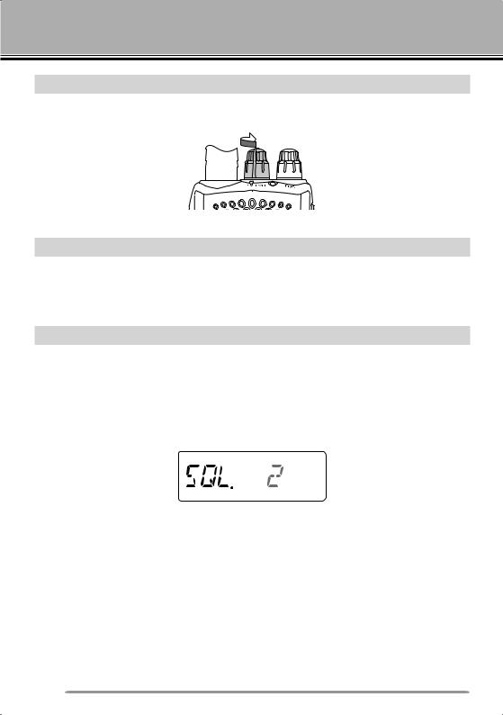
ADJUSTING THE SQUELCH
The purpose of Squelch is to mute the speaker when no signals are present. With the squelch level correctly set, you will hear sound only while actually receiving signals. The higher the selected squelch level, the stronger the signals must be to receive. The appropriate squelch level depends on the ambient RF noise conditions.
1Press [SQL].
•The squelch level appears on the display.
2Rotate the ENC control to adjust the level.
•Select the level at which the background noise is just eliminated when no signal is present.
•The higher the level, the stronger the signals must be to receive.
•6 different levels can be set. 0: Minimum ~ 5: Maximum; 2 is the default value.
3Press any key other than [MONI] or [LAMP] to store the new setting and exit the squelch adjustment.
10

SELECTING A FREQUENCY
VFO MODE
This is the basic mode for changing the operating frequency. Rotate the ENC control clockwise to increase the frequency and counterclockwise to decrease the frequency.
MHz TUNING MODE
If the desired operating frequency is far away from the current frequency, it is quicker to use the MHz Tuning Mode.
To adjust the MHz digit:
1Press [F].
• The MHz digit blinks.
2Rotate the ENC control to select the desired MHz value.
3After selecting the desired MHz value, press [F] or [ENT] to exit the MHz Tuning Mode and return to normal VFO Mode.
4Continue adjusting the frequency as necessary, using the ENC control.
TRANSMITTING/ RECEIVING
1To transmit, hold the transceiver approximately 5 cm (2 inches) from your mouth, then press and hold [PTT] and speak into the microphone in your normal tone of voice.
•The TX-RX LED lights red.
2When you finish speaking, release [PTT].
•The TX-RX LED lights green while receiving a signal.
Note: If you continuously transmit for longer than the time specified in Menu No. 19 (default is 10 minutes), the internal time-out timer generates a warning beep and the transceiver stops transmitting. In this case, release [PTT] and let the transceiver cool down for a while, then press [PTT] again to resume transmitting.
11

DIRECT FREQUENCY ENTRY
In addition to rotating the ENC control, there is another way to select the frequency. When the desired frequency is far away from the current frequency, you can directly enter a frequency using the numeric keypad.
1Press [VFO].
•You must be in the VFO Mode to make the direct frequency entry.
2Press [ENT].
3Press the numeric keys ([STEP] (0) to [PF] (9)) to enter your desired frequency. [LAMP] ( ) allows you to complete the MHz digits entry.
•Pressing [ENT] fills all remaining digits (the digits you did not enter) with 0 and completes the entry. For example, to select 145.000 MHz, press [MENU] (1), [SQL] (4), and [T.SEL] (5), then press [ENT] to complete the entry.
•If you want to revise the MHz digits only, leaving the kHz digits as they are, press
[VFO] in place of [ENT].
Note:
If the entered frequency does not match the current frequency step size, the frequency is automatically rounded down to the next available frequency.
When the desired frequency cannot be entered exactly, confirm the frequency step size.
If you rotate the ENC control while entering the frequency, the transceiver clears the entry.
SELECTING AN OUTPUT POWER
Selecting a lower transmit power is the best way to reduce battery consumption, if communication is still reliable.
Press [LOW] to toggle between high, medium and low power.
•No icon appears when using high transmit power.
•The “ ” icon appears when using medium transmit power.
•The “ ” icon appears when using lower transmit power.
Note: When the transceiver overheats due to ambient high temperature or continuously transmitting, the protective circuit may activate, lowering the transmit output power.
12
REMAINING BATTERY CAPACITY
You can confirm the remaining battery capacity when you transmit in low power. To check the remaining capacity:
• |
remaining battery capacity. |
: |
High battery power |
: |
↑ |
: |
↑ |
: |
Low battery power |
or no display : |
Recharge or replace the batteries. |
Note: You may not be able to transmit at high power if the battery remaining indicator shows low battery power.
BACKLIGHT
Press [LAMP] to illuminate the display and keys.
•The light turns OFF approximately 5 seconds after releasing [LAMP].
•Press any key (including [PTT]) other than [LAMP] while the display and keys are lit to restart the 5-second timer.
•Continuing to press [LAMP] after having pressed it will illuminate the display and keys for as long as you hold the key.
Press [F] - [LAMP] to keep the light ON continuously.
•The light remains ON until you press [F] - [LAMP] again.
MONITOR
When you are receiving while the squelch function is ON, weak signals may become intermittent.
If the CTCSS, DCS or Tone Alert function is ON, you may want to disable the squelch function temporarily to monitor the current channel activities.
1Press and hold [MONI].
• The speaker is unmuted and you can monitor the signals.
2Release [MONI] to return to normal operation.
13
 Loading...