


TK-890

INSTRUCTION MANUAL
GRP
POWER
TX
VOL
CH
BUSY
SCAN OPT OSTA B CMON
CALL
SP
MON
SCN
GRP
VOL
CH
POWER
TX
BUSY
VHF FM TRANSCEIVER
TK-690 series
VHF FM TRANSCEIVER
TK-790 series
UHF FM TRANSCEIVER
Downloaded from: http://www.usersmanualguide.com/
TK-890 series
© B62-0970-20 (K)
09 08 07 06 05 04 03 02

THANK YOU!
We are grateful you chose KENWOOD for your land mobile applications. We
believe this easy-to-use transceiver will provide dependable communications to
keep personnel operating at peak efficiency.
KENWOOD transceivers incorporate the latest in advanced technology. As a
result, we feel strongly that you will be pleased with the quality and features of
this product.
MODELS COVERED BY THIS MANUAL
••
• TK-690H: VHF FM Transceiver
••
••
• TK-790: VHF FM Transceiver
••
••
• TK-790H: VHF FM Transceiver
••
••
• TK-890: UHF FM Transceiver
••
••
• TK-890H: UHF FM Transceiver
••
Downloaded from: http://www.usersmanualguide.com/

NOTICES TO THE USER
◆
GOVERNMENT LAW PROHIBITS THE OPERATION OF UNLICENSED RADIO
TRANSMITTERS WITHIN THE TERRITORIES UNDER GOVERNMENT CONTROL.
◆
ILLEGAL OPERATION IS PUNISHABLE BY FINE OR IMPRISONMENT OR BOTH.
◆
REFER SERVICE TO QUALIFIED TECHNICIANS ONLY.
SAFETY: It is important that the operator is aware of, and understands, hazards
common to the operation of any transceiver.
WARNING!
◆
EXPLOSIVE ATMOSPHERES (GASES, DUST, FUMES, etc.)
Turn OFF your transceiver while taking on fuel or while parked in a gasoline service station. Do
not carry spare fuel containers in the trunk of your vehicle if your transceiver is mounted in the
trunk area.
◆
INJURY FROM RADIO FREQUENCY TRANSMISSIONS
Do not operate your transceiver when somebody is within two to three feet of the antenna, to
avoid the possibility of radio frequency burns or related physical injury.
◆
DYNAMITE BLASTING CAPS
Turn OFF your transceiver when in an area where blasting is in progress, or where “TURN OFF
TWO-WAY RADIO” signs have been posted. Operating the transceiver within 150 meters
(500 feet) of dynamite blasting caps may cause them to explode. If you are carrying blasting
caps in your vehicle, make sure they are enclosed in a metal box with a padded interior. Do not
transmit while the caps are being placed into or are being removed from the container.
Note:
This instruction manual covers only the basic functions of the transceiver. Consult your dealer
for more detailed information.
One or more of the following statements may be applicable:
FCC WARNING
This equipment generates or uses radio frequency energy. Changes or modifications to this
equipment may cause harmful interference unless the modifications are expressly approved in the
instruction manual. The user could lose the authority to operate this equipment if an unauthorized
change or modification is made.
INFORMATION TO THE DIGITAL DEVICE USER REQUIRED BY THE FCC
This equipment has been tested and found to comply with the limits for a Class B digital device,
pursuant to Part 15 of the FCC Rules. These limits are designed to provide reasonable protection
against harmful interference in a residential installation. This equipment generates, uses and can
generate radio frequency energy and, if not installed and used in accordance with the instructions,
may cause harmful interference to radio communications. However, there is no guarantee that the
interference will not occur in a particular installation. If this equipment does cause harmful
interference to radio or television reception, which can be determined by turning the equipment off
and on, the user is encouraged to try to correct the interference by one or more of the following
measures:
•
Reorient or relocate the receiving antenna.
•
Increase the separation between the equipment and receiver.
•
Connect the equipment to an outlet on a circuit different from that to which the receiver is
connected.
•
Consult the dealer for technical assistance.
Downloaded from: http://www.usersmanualguide.com/
i

CONTENTS
UNPACKING AND CHECKING EQUIPMENT ............................................... 1
Supplied Accessories .............................................................................. 1
PREPARATION ............................................................................................... 3
Tools Required ......................................................................................... 3
Power Cable Connection ........................................................................ 3
Installing the Transceiver........................................................................ 4
GETTING ACQUAINTED ................................................................................5
Basic Front Panel (KCH-10) .................................................................... 5
Basic Panel Display ................................................................................. 6
Full-featured Front Panel (KCH-11)........................................................ 7
Full-featured Panel Display .................................................................... 9
Rear Panel ............................................................................................... 10
Microphone ............................................................................................. 10
PROGRAMMABLE FUNCTIONS ................................................................. 11
BASIC OPERATIONS ................................................................................... 15
Switching Power ON/ OFF .................................................................... 15
Adjusting the Volume ............................................................................ 15
Selecting a Group .................................................................................. 15
Selecting a Channel ............................................................................... 15
Making a Call .......................................................................................... 15
DTMF CALLS ................................................................................................ 16
Manual Dialing ........................................................................................ 16
Redialing ................................................................................................. 16
Auto Dialing ............................................................................................ 16
OTHER TRANSCEIVER FUNCTIONS ......................................................... 18
Time-out Timer (TOT) ............................................................................ 18
Busy Channel Lockout (BCL) ...............................................................18
Operator Selectable Priority Channel .................................................. 18
2Tone/ DTMF Signaling ......................................................................... 18
Roll Over/ Dead End .............................................................................. 19
Dead Beat Disable (DBD) ...................................................................... 19
Timed Power OFF................................................................................... 19
ii
Downloaded from: http://www.usersmanualguide.com/

UNPACKING AND CHECKING EQUIPMENT
Note:
The following unpacking instructions are for use by your
KENWOOD
service facility, or the factory.
Carefully unpack the transceiver. We recommend that you identify the items
listed in the following table before discarding the packing material. If any items
have been damaged during shipment, file a claim with the carrier immediately.
■ Supplied Accessories
KENWOOD
TK-690
dealer, an authorized
Quantity
TK-890
TK-790
TK-890
TK-790
TK-790
TK-890
Item
Microphone and
microphone cable
1
Microphone hanger J19-1584-X5
Mounting bracket J29-0422-X3
Power cable assembly E30-3318-X5
Fuse (15 A)
Speaker short plug
Cover F07-1336-X5
Retaining band J61-0307-X5
Knob
Hex-headed screw N09-2177-X5
Self-tapping screw
(5 x 16 mm)
Self-tapping screw
(4 x 16 mm)
Spring washer
Flat washer
Warranty card
(USA/ Canada only)
Instruction manual
1
The microphone cable can also be ordered separately as E30-3313-X8.
Part Number
T91-0587-X5
F05-1537-X5
E37-0733-X5
K29-4704-X4
K29-5276-X3
K29-5277-X3
K29-5305-X3
N09-0335-X5
N46-4016-X6
N16-0050-X6
N15-1050-X6
B46-0470-XX
B62-0970-XX
(B)
H
–
–
–
–
(B)
1
–
1
–
1
–
1
–
3
–
(B)
H
–
–
–
–
–
(B)
1–
–
1
–
1
–
1
–
3
–
1 111111
1 111111
1 1111
–––––
–––––
11
–––––
11
–––––
11
11111
–––––
–––––
33
–––––
–––––
11
55
77
44
44
44
1 111111
1 111111
(B)
H
–
–
–
–
–
Downloaded from: http://www.usersmanualguide.com/
1
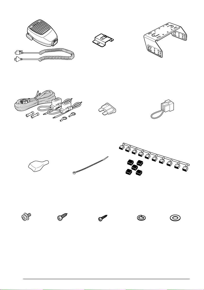
Microphone and
microphone cable
Microphone hanger
Mounting bracket
Power cable
assembly
Cover
Hex-headed
screw
Self-tapping screw
(5 x 16 mm)
Fuse (15 A)
Retaining band
Self-tapping screw
(4 x 16 mm)
Speaker short plug
Knob
Spring washer
Flat washer
2
Downloaded from: http://www.usersmanualguide.com/

PREPARATION
WARNING!
◆
VARIOUS ELECTRONIC EQUIPMENT IN YOUR VEHICLE MAY MALFUNCTION IF THEY ARE
NOT PROPERLY PROTECTED FROM THE RADIO FREQUENCY ENERGY WHICH IS PRESENT
WHILE TRANSMITTING. ELECTRONIC FUEL INJECTION, ANTI-SKID BRAKING, AND CRUISE
CONTROL SYSTEMS ARE TYPICAL EXAMPLES OF EQUIPMENT THAT MAY MALFUNCTION.
IF YOUR VEHICLE CONTAINS SUCH EQUIPMENT, CONSULT THE DEALER FOR THE MAKE
OF VEHICLE AND ENLIST HIS AID IN DETERMINING IF THEY WILL PERFORM NORMALLY
WHILE TRANSMITTING.
◆
ALTHOUGH THE REMOTE PANELS ARE WATER RESISTANT, THE MAIN TRANSCEIVER BODY
IS NOT. MOUNT IT IN A PLACE WHERE IT WILL NOT GET WET.
Note:
The following preparation instructions are for use by your
KENWOOD
service facility, or the factory.
■ Tools Required
Note
: Before installing the transceiver, always check how far the mounting screws will extend below
the mounting surface. When drilling mounting holes, be careful not to damage vehicle wiring or
parts.
The following tools are required for installing the transceiver:
• 6 mm (1/4 inch) or larger electric drill
• Drill bits (sizes listed below) and circle cutters
eziStiBllirD esopruP
)hcni23/5(mm2.4swercsgnippat-flesmm61x5
)hcni8/1(mm2.3swercsgnippat-flesmm61x4
KENWOOD
dealer, an authorized
■ Power Cable Connection
CAUTION:
CHECK THE BATTERY POLARITY AND VOLTAGE OF THE VEHICLE BEFORE INSTALLING THE
TRANSCEIVER.
THE TRANSCEIVER OPERATES IN 12 V NEGATIVE GROUND SYSTEMS ONLY!
1 Check for an existing hole, conveniently located in the firewall, where the
power cable can be passed through.
• If no hole exists, use a circle cutter to drill the firewall, then install a rubber
grommet.
2 Run the two power cable leads through the fire wall and into the engine
compartment, from the passenger compartment.
3 Connect the red lead to the positive (+) battery terminal and the black lead
to the negative (–) battery terminal.
• Locate the fuse as close to the battery as possible.
4 Coil and secure the surplus cable with the provided retaining band.
• Be sure to leave enough slack in the cables so the transceiver can be removed
for servicing while keeping the power applied.
Downloaded from: http://www.usersmanualguide.com/
3

■ Installing the Transceiver
WARNING!
SUPPLIED MOUNTING BRACKET, SO THE TRANSCEIVER WILL NOT BREAK LOOSE IN THE
EVENT OF A COLLISION.
FOR PASSENGER SAFETY, INSTALL THE TRANSCEIVER SECURELY, USING THE
1 Mark the position of the holes in the dash by using the mounting bracket
as a template. Drill the holes, then attach the mounting bracket using the
supplied 5 x 16 mm screws.
• Be sure to mount the transceiver in a location where the controls will be within
easy reach of the user, and where there is sufficient space at the rear of the
transceiver for cable connections.
2 Connect the antenna and the supplied power cable to the transceiver.
3 Slide the transceiver into the mounting bracket and secure it using the
supplied hex-headed screws.
4 Mount the microphone hanger, using the supplied 4 x 16 mm screws, in a
location where it will be within easy reach of the user.
• The microphone and microphone cable should be mounted in a place where
they will not interfere with the safe operation of the vehicle.
5 Connect one plug of the microphone cable to the jack on the base of the
microphone, and the other plug to the microphone jack on the front panel
of the transceiver. Place the microphone on the hanger.
Microphone
Microphone
hanger
Mounting bracket
Microphone cable
Transceiver
Power input
connector
Antenna
connector
Power cable
Red wire
Black wire
4
Downloaded from: http://www.usersmanualguide.com/
Fuse
Fuse holder
Hex headed
screw
Battery
 Loading...