


TK-880

TK-780/ TK-880
VHF FM TRANSCEIVER/ UHF FM TRANSCEIVER
INSTRUCTION MANUAL
ÉMETTEUR-RÉCEPTEUR FM VHF/ ÉMETTEUR-RÉCEPTEUR FM UHF
MODE D’EMPLOI
TRANSCEPTOR FM VHF/ TRANSCEPTOR FM UHF
MANUAL DE INSTRUCCIONES
VHF-FM-TRANSCEIVER/ UHF-FM-TRANSCEIVER
BEDIENUNGSANLEITUNG
RICETRASMETTITORE FM VHF/ RICETRASMETTITORE FM UHF
MANUALE DI ISTRUZIONI
VHF FM ZENDONTVANGER/ UHF FM ZENDONTVANGER
GEBRUIKSAANWIJZING
KENWOOD CORPORATION
© B62-1438-10 (E)
09 08 07 06 05 04 03 02 01

VHF FM TRANSCEIVER/
UHF FM TRANSCEIVER
TK-780/ TK-880
INSTRUCTION MANUAL
KENWOOD CORPORATION

THANK YOU!
We are grateful you chose KENWOOD for your personal mobile applications.
We believe this easy-to-use transceiver will provide dependable communications
to keep personnel operating at peak efficiency.
KENWOOD transceivers incorporate the latest in advanced technology. As a
result, we feel strongly that you will be pleased with the quality and features of
this product.
MODELS COVERED BY THIS MANUAL
• TK-780: VHF FM Transceiver
• TK-880: UHF FM Transceiver
PRECAUTIONS
Please observe the following precautions to prevent fire, personal injury, and
transceiver damage.
• Do not attempt to configure the transceiver while driving; it is too dangerous.
• Do not modify the transceiver for any reason.
• Do not expose the transceiver to long periods of direct sunlight, nor place it near
heating appliances.
• Do not place the transceiver in excessively dusty, humid, or wet areas, nor on
unstable surfaces.
• If an abnormal odour or smoke is detected coming from the transceiver, turn OFF the
power immediately. Contact your KENWOOD dealer.
NOTICES TO THE USER
◆
GOVERNMENT LAW PROHIBITS THE OPERATION OF UNLICENSED RADIO
TRANSMITTERS WITHIN THE TERRITORIES UNDER GOVERNMENT CONTROL.
◆
ILLEGAL OPERATION IS PUNISHABLE BY FINE AND/OR IMPRISONMENT.
◆
REFER SERVICE TO QUALIFIED TECHNICIANS ONLY.
SAFETY: It is important that the operator is aware of, and understands, hazards
common to the operation of any transceiver.
WARNING!
◆
EXPLOSIVE ATMOSPHERES (GASES, DUST, FUMES, etc.)
Turn OFF your transceiver while taking on fuel or while parked in a gasoline service station. Do
not carry spare fuel containers in the trunk of your vehicle if your transceiver is mounted in the
trunk area.
◆
INJURY FROM RADIO FREQUENCY TRANSMISSIONS
Do not operate your transceiver when somebody is either touching the antenna or standing within
two to three feet of it, to avoid the possibility of radio frequency burns or related physical injury.
◆
DYNAMITE BLASTING CAPS
Operating the transceiver within 500 feet of dynamite blasting caps may cause them to explode.
Turn OFF your transceiver when in an area where blasting is in progress, or where “TURN OFF
TWO-WAY RADIO” signs have been posted. If you are transporting blasting caps in your vehicle,
make sure they are carried in a closed metal box with a padded interior. Do not transmit while
the caps are being placed into or removed from the container.
i

CONTENTS
UNPACKING AND CHECKING EQUIPMENT ............................................ 1
SUPPLIED ACCESSORIES .................................................................. 1
PREPARATION ........................................................................................... 2
TOOLS REQUIRED ............................................................................... 2
POWER CABLE CONNECTION ...........................................................2
INSTALLING THE TRANSCEIVER ....................................................... 3
ORIENTATION............................................................................................. 4
FRONT PANEL ...................................................................................... 4
DISPLAY ................................................................................................ 5
REAR PANEL ........................................................................................ 5
PROGRAMMABLE AUXILIARY FUNCTIONS ........................................... 6
BASIC OPERATIONS ................................................................................. 8
OPERATION OVERVIEW ...................................................................... 8
SWITCHING POWER ON/ OFF ............................................................ 8
ADJUSTING THE VOLUME .................................................................. 8
SELECTING A GROUP/ CHANNEL ..................................................... 8
MAKING A CALL ................................................................................... 8
RECEIVING A CALL.............................................................................. 8
TIME-OUT TIMER (TOT) ....................................................................... 9
HORN ALERT ........................................................................................ 9
ADVANCED OPERATIONS ......................................................................10
SCAN ................................................................................................... 10
Priority Scan .................................................................................. 10
5-TONE SIGNALLING ......................................................................... 10
DMS: ALPHANUMERIC 2-WAY PAGING FUNCTION ........................... 11
KEY FUNCTIONS ................................................................................ 11
SELCALL (SELECTIVE CALLING) .................................................... 12
Transmitting .................................................................................. 12
Receiving .......................................................................................12
Identification Codes ..................................................................... 12
STATUS MESSAGE ............................................................................ 13
Transmitting .................................................................................. 13
Receiving .......................................................................................13
Reviewing Messages in the Queue Memory .............................. 14
Automatic Status Response ........................................................ 14
SHORT MESSAGES FEATURE ......................................................... 14
GPS REPORT ...................................................................................... 14
DTMF (DUAL TONE MULTI FREQUENCY) CALLS ................................ 15
MAKING A DTMF CALL ...................................................................... 15
DTMF SIGNALLING ............................................................................ 15
STUN .................................................................................................... 15
AUDIBLE USER FEEDBACK TONES ..................................................... 16
ii
UNPACKING AND CHECKING EQUIPMENT
Note:
The following unpacking instructions are for use by your
KENWOOD
service facility, or the factory.
Carefully unpack the transceiver. We recommend that you identify the items
listed in the following table before discarding the packing material. If any items
are missing or have been damaged during shipment, file a claim with the carrier
immediately.
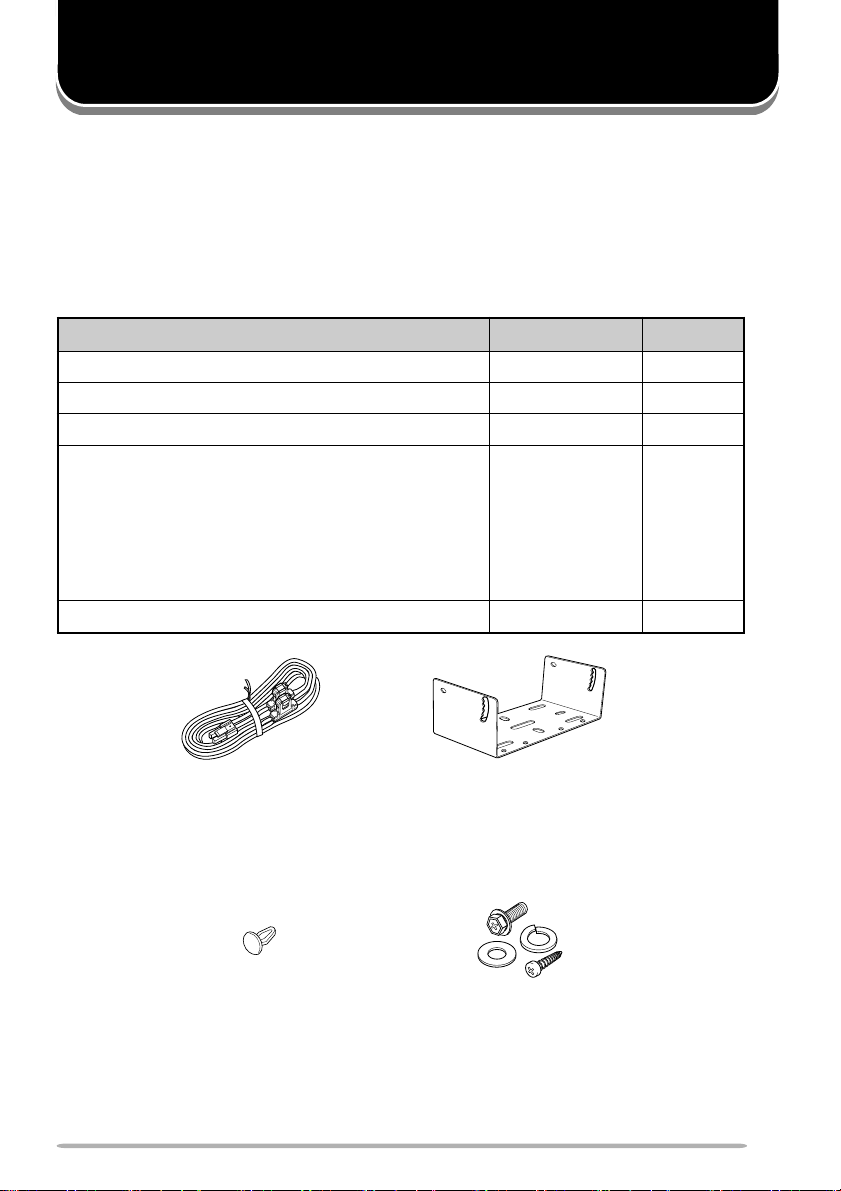
SUPPLIED ACCESSORIES
metI rebmuNtraP ytitnauQ
elbacrewopCDXX-8343-03E1
tekcarbgnitnuoMXX-7260-92J1
packcajrekaepSXX-5320-90B1
:teswercS
)seceip4(wercsgnippat-fleS•
)seceip4(rehsawgnirpS•
)seceip4(rehsawtalF•
launamnoitcurtsnIXX-8341-26B1
KENWOOD
)seceip4(rehsawhtiwwercsdedaeh-xeH•
dealer, an authorized
XX-5930-99N1
DC power cable Mounting bracket
Screw setSpeaker jack cap
1

PREPARATION
VARIOUS ELECTRONIC EQUIPMENT IN YOUR VEHICLE MAY MALFUNCTION IF THEY ARE
NOT PROPERLY PROTECTED FROM THE RADIO FREQUENCY ENERGY WHICH IS PRESENT
WHILE TRANSMITTING. ELECTRONIC FUEL INJECTION, ANTI-SKID BRAKING, AND CRUISE
CONTROL SYSTEMS ARE TYPICAL EXAMPLES OF EQUIPMENT THAT MAY MALFUNCTION. IF
YOUR VEHICLE CONTAINS SUCH EQUIPMENT, CONSULT THE DEALER FOR THE MAKE OF
VEHICLE AND ENLIST HIS AID IN DETERMINING IF THEY WILL PERFORM NORMALLY WHILE
TRANSMITTING.
Note
: The following preparation instructions are for use by your
KENWOOD
service facility, or the factory.
TOOLS REQUIRED
Note
: Before installing the transceiver, always check how far the mounting screws will extend below the
mounting surface. When drilling mounting holes, be careful not to damage vehicle wiring or parts.
The following tools are required for installing the transceiver:
•A 6 mm (1/4 inch) or larger electric drill.
•A 4.2 mm (5/32 inch) drill bit for the 5 x 16 mm self-tapping screws, and a 3.2 mm
(1/8 inch) drill bit for the 4 x 16 mm self-tapping screws.
• Circle cutters.
POWER CABLE CONNECTION
KENWOOD
dealer, an authorized
◆
THE TRANSCEIVER OPERATES IN 12 V NEGATIVE GROUND SYSTEMS ONLY! CHECK
THE BATTERY POLARITY AND VOLTAGE OF THE VEHICLE BEFORE INSTALLING THE
TRANSCEIVER.
◆
LOCATE THE POWER INPUT CONNECTOR AS CLOSE TO THE TRANSCEIVER AS
POSSIBLE.
1 Check for an existing hole, conveniently located in the firewall, where the
power cable can be passed through.
• If no hole exists, use a circle cutter to drill the firewall, then install a rubber
grommet.
2 Run the two power cable leads through the firewall and into the engine
compartment, from the passenger compartment.
3 Connect the red lead to the positive (+) battery terminal and the black lead to
the negative (–) battery terminal.
• Locate the fuse as close to the battery as possible.
4 Coil and secure the surplus cable with a retaining band.
• Be sure to leave enough slack in the cables so the transceiver can be removed for
servicing while keeping the power applied.
2
 Loading...