


 Loading...
VHF FM TRANSCEIVER
TK-7108H
SERVICE MANUAL
© 2002-7 PRINTED IN JAPAN B51-8638-00 (N) PDF
Chassis |
Cabinet |
Front glass |
Panel assy |
(A10-4048-11) |
(A01-2181-01) |
(B10-2668-03) |
(A62-0942-03) |
Modular jack |
Key top |
(E08-0877-05) |
(K29-9065-01) |
CONTENTS
GENERAL .................................................. |
2 |
ADJUSTMENT ........................................ |
27 |
OPERATING FEATURES .......................... |
3 |
TERMINAL FUNCTION ........................... |
32 |
REALIGNMENT ......................................... |
7 |
PC BOARD |
|
DISASSEMBLY FOR REPAIR ................... |
9 |
DISPLAY UNIT (X54-3340-20) ............ |
33 |
CIRCUIT DESCRIPTION .......................... |
10 |
TX-RX UNIT (X57-6383-01) ................ |
35 |
SEMICONDUCTOR DATA ...................... |
15 |
SCHEMATIC DIAGRAM .......................... |
41 |
COMPONENTS DESCRIPTION .............. |
17 |
BLOCK DIAGRAM ................................... |
45 |
PARTS LIST ............................................. |
19 |
LEVEL DIAGRAM .................................... |
47 |
EXPLODED VIEW .................................... |
25 |
SPECIFICATIONS .................................... |
49 |
PACKING ................................................. |
26 |
|
|
|
|
|
|
TK-7108H
GENERAL
INTRODUCTION
SCOPE OF THIS MANUAL
This manual is intended for use by experienced technicians familiar with similar types of commercial grade communications equipment. It contains all required service information for the equipment and is current as of this publication date. Changes which may occur after publication are covered by either Service Bulletins or Manual Revisions, which are issued as required.
ORDERING REPLACEMENT PARTS
When ordering replacement parts or equipment information, the full part identification number should be included. This applies to all parts : components, kits, and chassis. If the part number is not known, include the chassis or kit number of which it is a part and a sufficient description of the required component for proper identification.
PERSONNEL SAFETY
The following precautions are recommended for personnel safety :
•DO NOT transmit if someone is within two feet (0.6 meter) of the antenna.
•DO NOT transmit until all RF connectors are secure and any open connectors are properly terminated.
•SHUT OFF this equipment when near electrical blasting caps or while in an explosive atmosphere.
•All equipment should be properly grounded before powerup for safe operation.
•This equipment should be serviced by only qualified technicians.
PRE-INSTALLATION CONSIDERNATIONS
3. PRE-INSTALLATION CHECKOUT
3-1. Introduction
Each radio is adjusted and tested before shipment. However, it is recommended that receiver and transmitter operation be checked for proper operation before installation.
3-2. Testing
The radio should be tested complete with all cabling and accessories as they will be connected in the final installation. Transmitter frequency, deviation, and power output should be checked, as should receiver sensitivity, squelch operation, and audio output. Signalling equipment operation should be verified.
4. PLANNING THE INSTALLATION
4-1. General
Inspect the vehicle and determine how and where the radio antenna and accessories will be mounted.
Plan cable runs for protection against pinching or crushing wiring, and radio installation to prevent overheating.
4-2. Antenna
The favored location for an antenna is in the center of a large, flat conductive area, usually at the roof center. The trunk lid is preferred, bond the trunk lid and vehicle chassis using ground straps to ensure the lid is at chassis ground.
4-3. Radio
The universal mount bracket allows the radio to be mounted in a variety of ways. Be sure the mounting surface is adequate to support the radio’s weight. Allow sufficient space around the radio for air cooling. Position the radio close enough to the vehicle operator to permit easy access to the controls when driving.
1. UNPACKING
Unpack the radio from its shipping container and check for accessory items. If any item is missing, please contact KENWOOD immediately.
2. LICENSING REQUIREMENTS
Federal regulations require a station license for each radio installation (mobile or base) be obtained by the equipment owner. The licensee is responsible for ensuring transmitter power, frequency, and deviation are within the limits permitted by the station license.
Transmitter adjustments may be performed only by a licensed technician holding an FCC first, second or general class commercial radiotelephone operator’s license. There is no license required to install or operate the radio.
4-4. DC Power and wiring
1.This radio may be installed in negative ground electrical systems only. Reverse polarity will cause the cable fuse to blow. Check the vehicle ground polarity before installation to prevent wasted time and effort.
2.Connect the positive power lead directly to the vehicle battery positive terminal. Connecting the Positive lead to any other positive voltage source in the vehicle is not recommended.
3.Connect the ground lead directly to the battery negative terminal.
4.The cable provided with the radio is sufficient to handle the maximum radio current demand. If the cable must be extended, be sure the additional wire is sufficient for the current to be carried and length of the added lead.
2
TK-7108H
GENERAL / OPERATING FEATURES
5. INSTALLATION PLANNING – CONTROL STATIONS
5-1. Antenna system
Control station. The antenna system selection depends on many factors and is beyond the scope of this manual. Your KENWOOD dealer can help you select an antenna system that will best serve your particular needs.
5-2. Radio location
Select a convenient location for your control station radio which is as close as practical to the antenna cable entry point. Secondly, use your system’s power supply (which supplies the voltage and current required for your system). Make sure sufficient air can flow around the radio and power supply to allow adequate cooling.
SERVICE
OPERATING FEATURES
1. Controls and Functions
1-1. Front Panel
q w e |
|
|
r t |
|
|
i |
||||||||||||
|
|
|
|
|
|
|
|
|
|
|
|
|
|
|
|
|
|
|
|
|
|
|
|
|
|
|
|
|
|
|
|
|
|
|
|
|
|
|
|
|
|
|
|
|
|
|
|
|
|
|
|
|
|
|
|
|
|
|
|
|
|
|
|
|
|
|
|
|
|
|
|
|
|
|
|
|
|
|
|
|
|
|
|
|
|
|
|
|
|
|
|
|
|
|
|
|
|
|
|
|
|
|
|
|
|
|
|
|
|
|
|
|
|
|
|
|
|
|
|
|
|
|
|
|
|
|
|
|
|
|
|
|
|
|
|
|
|
|
|
|
|
|
|
|
|
|
|
|
|
|
|
|
|
|
|
|
|
|
|
|
|
|
|
|
|
|
|
|
|
|
|
|
|
|
|
|
|
|
|
|
|
|
|
|
|
|
|
|
|
|
|
|
|
|
|
|
|
|
|
|
|
|
|
|
|
|
|
|
uy
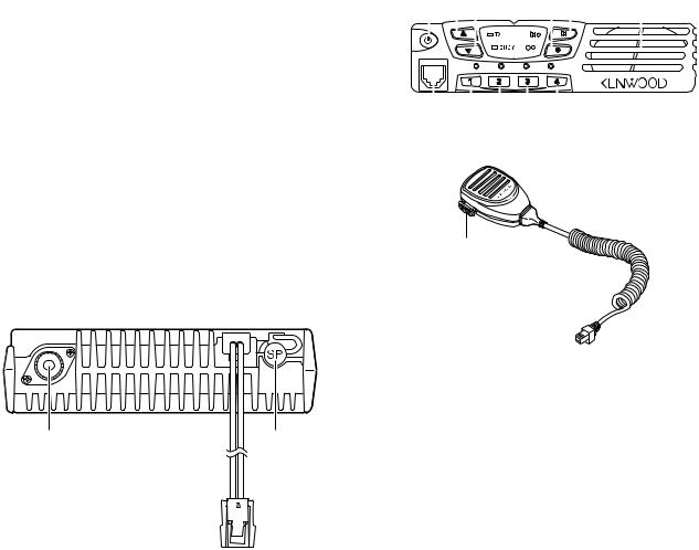
1-2. Microphone
This radio is designed for easy servicing. Refer to the schematic diagrams, printed circuit board views, and alignment procedures contained in this manual.
NOTE
If you do not intend to use the 3.5-mm jack for the external speaker, fit the supplied speaker-jack cap to stop dust and sand getting in.
Antenna |
Speaker |
connector |
jack cap |
Power input connector
o
q  (Power) switch
Press to switch the transceiver ON. Press and hold for approximately 1 seconds to switch the transceiver OFF.
w ▲ key
Press to increase the volume level. e ▼ key
Press to decrease the volume level.
r● key
PF (Programmable Function) key. The default setting of this key is None (no function). The programmable func-
tions available for this key are listed below.
t key
key
PF (Programmable Function) key. The default setting of
this key is Monitor. Other programmable functions available for this key are listed below.
y 1/ 2/ 3/ 4 keys
Press to select a channel from 1 to 4. When using the Group function, press to select a channel from 5 to 8.
u Microphone jack
Insert the microphone plug into this jack (the microphone is an optional accessory).
i Speaker Internal speaker.
oPTT switch
Press this switch, then speak into the microphone to call a station.
1-3. Auxiliary Programmable Functions
• |
Emergency |
• |
None (no function) |
• |
Group |
• |
Scan On/Off |
• |
Key Lock |
• |
Talk Around |
• |
Monitor |
• |
Temporary Delete |
3
TK-7108H
OPERATING FEATURES
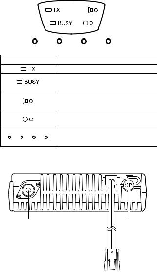
1-4. Display
2. Operation Features
Indicator |
Description |
Light while transmitting.
Lights when a signal is detected on the currently selected channel.
Lights while the function programmed onto its corresponding key is activated.
Lights while the function programmed onto its corresponding key is activated.
Lights to display the currently selected channel (1~ 4 or 5~8).
1-5. Rear panel
Antenna |
External |
connector |
speaker |
|
jack |
Power input connector
The TK-7108H is a VHF FM radio designed to operate in conventional format. The programmable features are summarized.
3. Transceiver Controls and Indicators
3-1. Front Panel Controls
All the keys on the front panel are momentary-type push buttons. The functions of these keys are explained below.
• POWER key
Transceiver POWER key. When the power is switched off, all the parameters are stored in memory. When the power is switched on again, the transceiver returns to the previous conditions.
•CHANNEL keys
•MONITOR key (Programmable)
•● key (Programmable)
•VOLUME UP/DOWN key
When the key is pressed, the volume level is increased/ decreased and repeats if held for 200ms or longer.
• BUSY/TX LED
The BUSY indicator (Green LED) shows that the channel is in use. The TX indicator (Red LED) shows that you are transmitting.
3-2. Programmable Keys
The FPU (KPG-70D) enables programmable keys to select the following functions.
•Emergency
•Key Lock
•Monitor
•Scan ON/OFF
•Talk Around
•Temporary Delete
•None
•Group
•Emergency
Pressing this key for longer than 1 second causes the
transceiver to enter the emergency mode. The transceiver jumps to the programmed “Emergency channel” and transmits for 25* seconds.
The transceiver disables mic mute while transmitting. After finishing transmission, the transceiver receivers for 5* seconds. The transceiver Mute* the speaker while receiving. Following the above sequence, the transceiver continues to transmit and receive.
* Default value.
4
TK-7108H
OPERATING FEATURES
• Key lock
Pressing this key causes the transceiver to accept entry of only the [Vol Up/Down]*, [Key lock], Microphone [PTT], [Monitor], [Emergency], and [Power] keys.
* Programmable
• Monitor
Used to release signalling (press once) or squelch (press and hold for approximately two seconds) when operating as a conventional. It is also used to reset option signalling.
• Scan ON/OFF
Press this key starts scanning. Pressing this key stops scanning.
• Talk around
Press this key, the transceiver uses the receive frequency and the tone for transmission.
The operator can call the other party directly (without repeater). Press this key again, the talk around function goes off.
• Temporary delete
The “Add” channel contained in the scan sequence, and “Delete” channel is not contained. In the scan mode, this key switches the channel delete temporarily (Press and hold for approximately one second).
When the transceiver is turned off, the transceiver exits the scan or switches the scan function off.
■ Scan stop condition
The scan stops temporarily if the following conditions are satisfied.
1)A carrier is detected, then QT/DQT matches on channels for which receive the QT/DQT is set by the programming software.
2)A carrier is detected on the channels for which receiving QT/DQT is not set by the programming software or when the monitor (signalling cancel) function is activated.
■ Revert channel
The revert channel is used to transmit during scanning and set by the programming software (KPG-70D).
1)Selected channel
The transceiver reverts to the channel before scanning or the channel that you changed during scan.
2)Selected with talkback
The transceiver reverts to the selected channel prior to scan initiation.
However, if a call is received on a channel other then the selected channel and PTT is pressed before scanning resume, the transceiver “talks back” on the current receive channel.
■ Scan end
When you press the key programmed to the scan function during scan mode, the scan ends.
The indicator next to the programmed key LED turns off.
■ Temporary delete
• None
Sounds error operation beep, and no action will occur. Use this function when the transceiver is required to be more simple operated.
• Group
If Group has been programmed onto a key, press the Group key to select the second group of channels. While active, the LED beside the key lights. At this time, press a key from 1 to 4 select a channel from 5 to 8. To return to channels 1 through 4, press the Group key again.
Note : You cannot use the Group function while operating in Emergency mode.
4. Scan Operating
■ SCAN start condition
Two or more channels must be added to all channels that can be scanned. The transceiver must be in normal receive mode (PTT off).
When you activate the key programmed to the scan ON/ OFF function, the scan starts. The indicator next to the programmed key LED blinks.
It is possible to delete channel temporary during scan. When scan stops on unnecessary channel for example by interference of the other party, activate the delete function (for example press and hold the key for approximately one second), then that channel is deleted temporarily and scan re-start immediately.
The temporary deleted channels return to pre-set delete/ add channels, when the transceiver is turned off or the scan function is switched off.
5. Details of Features
■ Time-out timer
The time-out timer can be programmed in 30 seconds increments from 30 seconds to five minutes and off. If the transmitter is transmitted continuously for longer than the programmed time, the transmitter is disabled and a warning tone sounds while the PTT button is held down. The warning tone stops when the PTT button is released.
5
TK-7108H
OPERATING FEATURES
■ PTT ID
PTT ID provides a DTMF ANI to be sent with every time PTT (beginning of transmission, end of transmission, or both).
You can program PTT ID “on” or “off” for each channel. The contents of ID are programmed each Radio.
The timing that the transceiver sends ID is programmable.
BOT : DTMF ID (Beginning of TX) is sent on beginning of transmission.
EOT : DTMF ID (End of TX) is sent on end of transmission.
Both : DTMF ID (Beginning of TX) is sent on beginning of transmission and DTMF ID (End of TX) is sent on end of transmission.
■ Off hook decode
If the Off hook decode function has been enabled, removing and replacing the microphone on the hook has no effect for decoding QT/DQT and option signalling.
■ “TOT” pre-alert
The transceiver has “TOT” pre-alert timer. This parameter selects the time at which the transceiver generates “TOT” pre-alert tone before “TOT” is expired.
“TOT” will be expired when the selected time passes from a TOT pre-alert tone.
■ “TOT” re-key time
The transceiver has “TOT” re-key timer. This timer is the time you can not transmit after “TOT” exceeded. After “TOT” re-key time expired you can transmit again.
■ “TOT” reset time
■ SP Unmute
You can select the type of SP Unmute system for each channel. The selection is as follows.
Carrier, QT/DQT:
Channel with this option will not check ID Code in order to open its speaker.
Carrier+DTMF, QT/DQT+DTMF:
Channel that is set with this option will have to check for ID Code in order to open its speaker.
Default:
Carrier, QT/DQT.
SP unmute |
Channel setting |
RX condition |
Speaker |
|
|
|
|
|
|
|
QT/DQT |
DTMF |
|
condition |
|
|
|
|
|
Carrier |
None |
None |
Carrier |
Sounds |
|
|
|
|
|
|
|
Yes |
Carrier |
Sounds |
|
|
|
|
|
|
|
|
Carrier+DTMF |
Sounds |
|
|
|
|
|
Carrier+DTMF |
None |
Yes |
Carrier |
Not Sounds |
|
|
|
|
|
|
|
|
Carrier+DTMF |
Sounds |
|
|
|
|
|
QT/DQT |
Yes |
None |
Carrier |
Not Sounds |
|
|
|
|
|
|
|
|
Carrier+QT/DQT |
Sounds |
|
|
|
|
|
|
|
Yes |
Carrier |
Not Sounds |
|
|
|
|
|
|
|
|
Carrier+QT/DQT |
Sounds |
|
|
|
|
|
|
|
|
Carrier+QT/DQT+DTMF |
Sounds |
|
|
|
|
|
|
|
|
Carrier+DTMF |
Not Sounds |
|
|
|
|
|
QT/DQT+DTMF |
Yes |
Yes |
Carrier |
Not Sounds |
|
|
|
|
|
|
|
|
Carrier+QT/DQT |
Not Sounds |
|
|
|
|
|
|
|
|
Carrier+QT/DQT+DTMF |
Sounds |
|
|
|
|
|
|
|
|
Carrier+DTMF |
Not Sounds |
|
|
|
|
|
The transceiver has “TOT” reset timer. This timer is the minimum wait time allowed during a transmission that will reset the “TOT” count.
“TOT” reset time causes the “TOT” to continue even after PTT is released unless the “TOT” reset timer has expired.
■ Clear to transpond
The transceiver waits the transpond of DTMF if channel is busy until channel open. This feature prevents the interference to other party.
6. Option Signalling (DTMF)
Built-in DTMF decoder is available for option signalling. It is possible to use individual call, group call, Stun.
If the option signalling matches, a predetermined action will occur.
If option signalling matches on a channel is set up with option signalling, the channel LED will flash and option signalling will be released. The transpond or alert tone will sound.
While option signalling matches (or if option signalling is deactivated when you are transmitting), you can mute or unmute QT/DQT/Carrier.
Note :
When QT/DQT is not used, QT/DQT and QT/DQT+DTMF can not be selected.
When DTMF is not used, Carrier+DTMF and QT/ DQT+DTMF can not be selected.
■ Auto Reset
If option signalling matches a group set up with option signalling, option signalling is released. After matching option signalling, option signalling will temporarily reset automatically.
■ Stun
If the stun code matches, a predetermined action will occur. Whether option signalling is activated or not, when stun matches on any channel, the transceiver will become TX inhibited or TX/RX inhibited. While stun is active, if the stun code + “#” code is received, stun will deactivate.
When stun matches, transpond will function. Alert will not be output.
6
TK-7108H
OPERATING FEATURES / REALIGNMENT
7. Audible User Feedback Tones
The transceiver outputs various combinations of tones to notify the user of the transceiver operating state.
Refer to the help file on the KPG-70D, regarding the functions that are not listed below.
■Stun on tone
When a stun code is received, transpond tone sounds.
■Stun off tone
When a stun release code is received, transpond tone sounds.
■ Group call tone
Sounds when a group call with the correct DTMF option signalling is received, repeats 7 times. You can select yes or no in the Alert tone level setting.
■ Individual call tone
Sounds when an individual call with the correct DTMF option signalling is received. You can select yes or no in the Alert tone level setting.
■ Key input error tone
Sounds when a key is pressed but that key cannot be used. You can select yes or no for the optional feature's warning tone.
REALIGNMENT
1. Modes
|
User mode |
|
|
|
|
|
|
|
|
|
|
|
|
|
|
|
|
|
|
|
|
|
|
|
|
|
|
|
|
|
|
|
|
|
|
|
Data program- |
|
|
|
PC mode |
|
|
|
|||
|
|
|
|
ming mode |
|
|
|
|
|
|
|
|
|
|
|
|
|
|
|
|
|
|
|
|
|
|
|
|
|
||
|
Clone mode |
|
|
|
PC test mode |
|
PC tuning mode |
|
|
|
|
|
|||
|
|
|
|
|
|
|
|
|
Mode |
|
Function |
||||
|
|
|
|
|
|
|
|
User mode |
For normal use. |
|
|||||
|
|
|
|
|
|
|
|
PC mode |
Used for communication between the |
||||||
|
|
|
|
radio and PC (IBM compatible). |
|||
|
|
|
|
|
|
|
|
Data programming |
Used to read and write frequency data |
||||||
mode |
and other features to and from the radio. |
||||||
|
|
|
|
|
|
|
|
PC test mode |
Used to check the radio using the PC. |
||||||
|
|
|
|
This feature is included in the FPU. |
|||
|
|
|
|
|
|
|
|
PC tuning mode |
Used to tune the radio using the PC. |
||||||
|
|
|
|
|
|
|
|
Clone mode |
Used to transfer programming data from |
||||||
|
|
|
|
one radio to another. |
|
||
|
|
|
|
|
|
|
|
■ Transpond tone
Sounds when an individual call with the correct DTMF option signalling is received. For group calls, only the group tone will sound, not the transpond tone.
■ Pre alert tone
Sounds prior to the TOT TX inhibit activation. If TOT pre alert is set, the tone sounds at the amount of time programmed, before the TOT expires (TOT time – TOT pre alert time = Pre alert tone sounding time). You can select yes or no for the optional feature's warning tone.
■ Transmit protection
The final FET is protected against heat while transmitting by making the radio cuts down TX power when the temperature of the final FET becomes higher than reference. After that, if the temperature continue to rise, transmission is stopped. The final FET is also protected against over voltage by having the radio to check that the voltage of power supply connected to the radio is not higher than about 17V when the radio is turned on, otherwise it can not transmit. In both cases when transmission is stopped, a beep will continue to sound until the PTT key is released.
2. How to Enter Each Mode
Mode |
Operation |
|
|
User mode |
Power ON |
|
|
PC mode |
Received commands from PC |
|
|
Clone mode |
[1]+Power ON (Two seconds) |
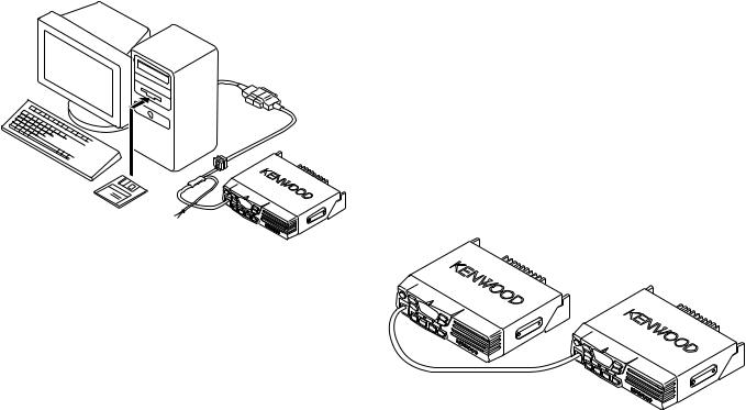
3. PC Mode
3-1. Preface
The TK-7108H transceiver is programmed using a personal computer, a programming interface (KPG-46) and programming software (KPG-70D).
The programming software can be used with an IBM PC or compatible. Figure 1 shows the setup of an IBM PC for programming.
7
TK-7108H
REALIGNMENT
3-2. Connection Procedure
1.Connect the TK-7108H to the personal computer with the interface cable.
2.When the Power is switched on, user mode can be entered immediately. When the PC sends a command, the radio enters PC mode.
When data is transmitted from transceiver, the red LED blink.
When data is received by the transceiver, the green LED blink.
In the PC mode, 4CH LEDs, [MON] LED and [●] LED are turned on.
Notes :
•The data stored in the personal computer must match model type when it is written into the EEPROM.
•Attach the interface cable, then change the TK-7108H to PC mode.
3-3. KPG-46 Description
(PC programming interface cable : Option)
The KPG-46 is required to interface the TK-7108H to the computer. It has a circuit in its D-subconnector (25-pin) case that converts the RS-232C logic level to the TTL level.
The KPG-46 connects the modular microphone jack of the TK-7108H to the computers RS-232C serial port.
IBM-PC
KPG-46
KPG-70D
TK-7108H
Fig. 1
3-4. Programming Software Description
The KPG-70D programming disk is supplied in 3-1/2" disk format. The software on this disk allows a user to program TK-7108H radio via a programming interface cable (KPG-46).
3-5. Programming With IBM PC
If data is transferred to the transceiver from an IBM PC with the KPG-70D, the destination data (basic radio information) for each set can be modified.
4. Clone Mode
Programming data can be transferred from one radio to another by connecting them via their modular microphone jacks. The operation is as follows (the transmit radio is the master and the receive radio is the slave).
Note :
Clone mode should enabled.
1.Turn the master TK-7108H power ON with the [1] key held down. The TK-7108H [●] LED is turned on.
2.Power on the slave TK-7108H.
3.Connect the cloning cable (No. E30-3382-05) to the modular microphone jacks on the master and slave.
4.Press the [●] key on the master TK-7108H transceiver. The data of the master is sent to the slave. While the master is sending data, [TX] LED blinked. While the slave is receiving the data, 4 LEDs, [MON] LED, [●] LED are turned on and [BUSY] LED blinked. When cloning of data is completed, the master [TX] LED turned off, and the slave automatically operates in the User mode. The slave can then be operated by the same program as the master.
5.The other slave can be continuously cloned. Carry out the operation in step 2 to 4.
4-1. Adding the data password.
If the data password is set in the optional feature menu, you must enter the password (Master transceiver) to activate a clone mode.
you can use 1, 2, 3, and 4 to configure the password. The maximum length of the password is 10 digits.
1.[1]+Power ON.
2.[1]~[4] LED, and MON LED are turned ON.
3.Enter the password using [1]~[4] keys.
4.Press [MON] key.
5.If the password matches, the transceiver enters a clone mode. Otherwise, transceiver beeps and returns to the password input mode.
Clone cable (E30-3382-05)
Fig. 2
8

TK-7108H
DISASSEMBLY FOR REPAIR
1.When you remove the panel, turn the transceiver up side down. Detach the panel by lifting the tabs as shown below.
3.To remove the display unit PCB, detach the PCB by lifting at the indents of the PCB as shown below.
Tabs
Indents
Fig. 1
Fig. 3
2.To remove the cabinet, first turn the transceiver up side down. Detach the cabinet by prying the tabs as shown below.
4.When mounting the front panel, match the 4 tabs of the chassis with the panel, being sure they attach securely.
Tabs
Tabs
Tabs
Tabs |
Fig. 4 |
Fig. 2
9
TK-7108H
CIRCUIT DESCRIPTION
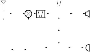
Frequency Configuration
The receiver utilizes double conversion. The first IF is 49.95MHz and the second IF is 450kHz. The first local oscillator signal is supplied from the PLL circuit.
The PLL circuit in the transmitter generates the necessary frequencies. Figure 1 shows the frequencies.
ANT |
|
|
|
|
|
|
|
|
|
|
|
|
|
|
|
CF 450kHz |
|
|
|
|
|
|
|||||||||||
|
|
|
|
|
|
|
|
|
|
1st |
|
|
MCF |
|
|
|
|
|
|
|
|
|
|
|
|
|
|
|
|||||
|
|
|
|
|
|
|
|
|
|
|
|
|
|
|
|
|
|
|
|
|
|
|
|
|
|
|
|||||||
|
|
|
|
|
|
|
|
|
MIX 49.95MHz |
|
|
|
|
|
|
|
|
|
|
|
|
|
|
|
|||||||||
ANT |
|
|
|
RF |
|
|
|
|
|
|
|
|
|
|
|
|
IF SYSTEM |
|
|
|
AF |
|
|
|
|
SP |
|||||||
|
|
|
|
|
|
|
|
|
|
|
|
|
|
|
|
|
|
|
|
|
|
||||||||||||
SW |
|
|
AMP |
|
|
|
|
|
|
|
|
|
|
|
|
|
|
|
PA |
|
|
|
|
||||||||||
|
|
|
|
|
|
|
|
|
|
|
|
|
|
|
|
|
|
|
|
|
|
|
|
|
|
|
|
||||||
|
|
|
|
|
|
|
|
|
|
|
|
|
|
|
|
|
|
|
|
|
|
50.4MHz |
|
|
|
|
|
|
|||||
|
|
|
|
|
|
|
|
|
|
|
|
|
|
|
|
|
|
|
|
|
|
|
|
|
|
|
|
||||||
|
|
|
|
|
|
|
|
|
|
|
|
|
|
|
|
|
|
|
|
|
X3 |
|
|
|
|
|
|
|
|
|
|
||
|
|
|
|
|
|
|
|
|
|
|
|
|
|
|
|
|
|
|
|
multiply |
|
|
|
|
|
|
|
|
|
|
|||
|
|
|
|
|
|
|
|
|
|
|
|
|
|
|
|
|
|
|
|
|
|
|
|
16.8MHz |
|
|
|
|
|
||||
|
|
|
|
|
|
|
|
|
|
|
|
|
|
|
|
|
|
|
|
TCXO |
|
|
|
|
|
||||||||
|
|
|
|
|
|
|
|
|
|
|
|
RX |
|
|
|
|
|
|
|
|
|
|
|
|
|
|
|
|
|
|
|
||
|
|
|
|
|
|
|
|
|
|
|
|
|
|
|
|
|
|
|
|
|
|
|
|
|
|
|
|
|
|
|
|||
|
|
|
|
|
|
|
|
|
|
|
|
|
|
|
|
|
|
|
|
|
|
|
|
|
|
|
|
|
|
|
|||
|
|
|
|
|
|
|
|
|
|
|
|
1/2 |
|
PLL/VCO |
|
|
|
MIC |
|
|
|
|
MIC |
||||||||||
POWER |
|
|
RF |
|
|
|
|
|
|
|
|
|
|
|
|
|
AMP |
|
|
|
|
||||||||||||
AMP |
|
|
AMP |
|
|
|
TX |
|
|
|
|
|
|
|
|
|
|
|
|
|
|
|
|
|
|
||||||||
|
|
|
|
|
|
|
|
|
|
|
|
|
|
|
|
|
|
|
|
|
|
|
|
||||||||||
Fig. 1 Frequency configuration
Receiver System
The receiver is double conversion superheterodyne. The frequency configuration is shown in Figure 1.
■ Front-end RF Amplifier
An incoming signal from the antenna is applied to an RF amplifier (Q26) after passing through a transmit/receive switch circuit (D804 is off) and a band pass filter (L36, L38 and varactor diodes: D25, D26). After the signal is amplified (Q26), the signal is filtered through a band pass filter (L30, L32 and varactor diodes: D21, D22) to eliminate unwanted signals before it is passed to the first mixer.
The voltage of these diodes are controlled by tracking the CPU (IC6) center frequency of the band pass filter. (See Fig. 2)
■ First Mixer
Item |
Rating |
|
|
|
|
Nominal center frequency |
49.95MHz |
|
|
|
|
Pass bandwidth |
±5.0kHz or more at 3dB |
|
|
|
|
35dB stop bandwidth |
±20.0kHz or less |
|
|
|
|
Ripple |
1.0dB or less |
|
|
|
|
Insertion loss |
5.0dB or less |
|
|
|
|
Guaranteed attenMuation |
80dB or more at fo±1MHz |
|
|
||
Spurious : 40dB or more within fo±1MHz |
||
|
||
|
|
|
Terminal impedance |
350Ω / 5.5pF |
|
Table 1 Crystal filter (L71-0591-05) : XF1 |
||
Item |
Rating |
|
|
Nominal center frequency |
450kHz |
|
|
6dB bandwidth |
±6.0kHz or more |
|
|
50dB bandwidth |
±12.5kHz or less |
|
|
Ripple |
2.0dB or less |
|
|
Insertion loss |
6.0dB or less |
|
|
Guaranteed attenuation |
35.0dB or more within fo±100kHz |
|
|
Terminal impedance |
2.0kΩ |
Table 2 Ceramic filter (L72-0993-05) : CF1 |
|
Item |
Rating |
|
|
Nominal center frequency |
450kHz |
|
|
6dB bandwidth |
±4.5kHz or more |
|
|
50dB bandwidth |
±10.0kHz or less |
|
|
Ripple |
2.0dB or less |
|
|
Insertion loss |
6.0dB or less |
|
|
Guaranteed attenuation |
60.0dB or more within fo±100kHz |
|
|
Terminal impedance |
2.0kΩ |
Table 3 Ceramic filter (L72-0999-05) : CF2
The signal from the RF amplifier is heterodyned with the first local oscillator signal from the PLL frequency synthesizer circuit at the first mixer (Q21) to create a 49.95MHz first intermediate frequency (1st IF) signal. The first IF signal is then fed through two monolithic crystal filters (MCFs : XF1) to further remove spurious signals.
■ IF Amplifier
The first IF signal is amplified by Q19, and the enters IC5 (FM processing IC). The signal is heterodyned again with a second local oscillator signal within IC5 to create a 450kHz second IF signal. The second IF signal is then fed through a 450kHz ceramic filter (Wide : CF1, Narrow : CF2) to further eliminate unwanted signals before it is amplified and FM detected in IC5.
10
Loading...