


INSTRUCTION MANUAL
FM TRIBANDER TH-F6
144/ 220/ 440 MHz FM TRIBANDER
TH-F6A
144/ 430 MHz FM DUAL BANDER
TH-F7E
KENWOOD CORPORATION
© B62-1441-00 (K,E,T)
09 08 07 06 05 04 03 02 01 00

MODELS COVERED BY THIS MANUAL
The models listed below are covered by this manual.
TH-F6A: 144/ 220/ 440 MHz FM Tri-band
Portable Transceiver
TH-F7E: 144/ 430 MHz FM Dual-band
Portable Transceiver
MARKET CODES
K-type: The Americas
E-type: Europe/ General
T-type: The United Kingdom
The market code is shown on the carton box.
Refer to the specifications {pages 53, 54} for the information on available operating frequencies within each model.
NOTICE TO THE USER
One or more of the following statements may be applicable for this equipment.
FCC WARNING
This equipment generates or uses radio frequency energy.
Changes or modifications to this equipment may cause harmful interference unless the modifications are expressly approved in the instruction manual. The user could lose the authority to operate this equipment if an unauthorized change or modification is made.
INFORMATION TO THE DIGITAL DEVICE USER REQUIRED BY THE FCC
This equipment has been tested and found to comply with the limits for a Class B digital device, pursuant to Part 15 of the
FCC Rules. These limits are designed to provide reasonable protection against harmful interference in a residential installation.
This equipment generates, uses and can generate radio frequency energy and, if not installed and used in accordance with the instructions, may cause harmful interference to radio communications. However, there is no guarantee that the interference will not occur in a particular installation. If this equipment does cause harmful interference to radio or television reception, which can be determined by turning the equipment off and on, the user is encouraged to try to correct the interference by one or more of the following measures:
•Reorient or relocate the receiving antenna.
•Increase the separation between the equipment and receiver.
•Connect the equipment to an outlet on a circuit different from that to which the receiver is connected.
•Consult the dealer for technical assistance.
PRECAUTIONS
Please observe the following precautions to prevent fire, personal injury, or transceiver damage:
•Do not transmit with high output power for extended periods. The transceiver may overheat.
•Do not modify this transceiver unless instructed by this manual or by KENWOOD documentation.
•When using a regulated power supply, connect the specified DC cable (option) to the DC IN jack on the transceiver. The supply voltage must be between 12 V and 16 V to prevent damaging the transceiver.
•When connecting the transceiver to a cigarette lighter socket in a vehicle, use the specified cigarette lighter cable (option).
•Do not expose the transceiver to long periods of direct sunlight nor place the transceiver close to heating appliances.
•Do not place the transceiver in excessively dusty areas, humid areas, wet areas, nor on unstable surfaces.
•If an abnormal odor or smoke is detected coming from the transceiver, turn OFF the power immediately and remove the battery case or the battery pack from the transceiver. Contact your authorized KENWOOD dealer, customer service, or service station.

THANK YOU
THANK YOU
Thank you for choosing this KENWOOD TH-F6A/ TH-F7E transceiver. It has been developed by a team of engineers determined to continue the tradition of excellence and innovation in KENWOOD transceivers.
First, don’t let the size fool you. This small FM portable transceiver features 2 m, 1.25 m (TH-F6A only), and 70 cm amateur radio band operation plus another all-mode 100 kHz to 1.3 GHz receiver (SSB and CW are up to 470 MHz). In the meantime, as you learn how to use this transceiver, you will also find that KENWOOD is pursuing “user friendliness”. For example, each time you change the Menu No. in Menu mode, you will see a text message on the display that lets you know what you are configuring.
Though user friendly, this transceiver is technically sophisticated and some features may be new to you. Consider this manual to be a personal tutorial from the designers. Allow the manual to guide you through the learning process now, then act as a reference in the coming years.
FEATURES
•Ultra compact design
•2 m, 1.25 m (TH-F6A only), and 70 cm amateur radio band FM transceiver operation
•A separate wide band, all-mode receiver, built-in
•Dual-frequency receive within the same amateur radio bands
•400 memory channels plus 34 special function memory channels (35 channels for TH-F6A)
•Long operation period with a Li-ion battery pack
•High output power (up to 5 W operation)
•Easy to control and select various functions with Multi-scroll key
•9600 bps Packet-ready data (Speaker/ Mic.) jack
•Built-in VOX function
•Meets MIL-STD 810C/ D/ E, Rain, Humidity, Vibration, and Shock
SUPPLIED ACCESSORIES
After carefully unpacking the transceiver, identify the items listed in the table below. We recommend you keep the box and packing material in case you need to repack the transceiver in the future.
|
|
Quantity |
|
||
Accessory |
Part Number |
|
|
|
|
TH-F6A |
TH-F7E |
||||
|
|
(K) |
(E) |
(T) |
|
|
|
|
|
|
|
Belt hook |
J29-0623-XX |
1 |
1 |
1 |
|
|
|
|
|
|
|
Antenna |
T90-0781-XX |
1 |
– |
– |
|
|
|
|
|
||
T90-0789-XX |
– |
1 |
1 |
||
|
|||||
|
|
|
|
|
|
Strap |
J69-0342-XX |
1 |
1 |
1 |
|
|
|
|
|
|
|
Line Filter |
L79-1417-XX |
– |
1 |
1 |
|
|
|
|
|
|
|
Li-ion battery |
W09-0979-XX |
1 |
1 |
1 |
|
|
|
|
|
|
|
|
W08-0927-XX |
1 |
– |
– |
|
|
|
|
|
|
|
Charger |
W08-0928-XX |
– |
1 |
– |
|
|
|
|
|
|
|
|
W08-0929-XX |
– |
– |
1 |
|
|
|
|
|
|
|
|
B62-1441-XX |
1 |
1 |
1 |
|
|
(E/ S) |
||||
|
|
|
|
||
Instruction |
B62-1442-XX |
– |
1 |
– |
|
Manual |
(F/ I) |
||||
|
|
|
|||
|
B62-1443-XX |
– |
1 |
– |
|
|
(D/ G) |
||||
|
|
|
|
||
|
|
|
|
|
|
R&TTE Notice |
B59-2267-XX |
– |
1 |
1 |
|
|
|
|
|
|
|
Warranty card |
— |
1 |
1 |
1 |
|
|
|
|
|
|
|
WRITING CONVENTIONS FOLLOWED
The writing conventions described below have been followed to simplify instructions and avoid unnecessary repetition.
Instruction |
|
|
What to Do |
|||
|
|
|
|
|
|
|
Press [KEY]. |
Press and release KEY. |
|||||
|
|
|
|
|
|
|
Press |
Press KEY1 momentarily, release |
|||||
[KEY1], [KEY2]. |
KEY1, then press KEY2. |
|||||
|
|
|
|
|
|
|
Press |
Press and hold KEY down for a |
|||||
[KEY] (1 s). |
second. |
|||||
|
|
|
|
|
|
|
|
|
|
Press and hold KEY1 down, then |
|||
Press |
press KEY2. If there are more |
|||||
than two keys, press and hold |
||||||
[KEY1]+[KEY2]. |
||||||
|
|
|
down each key in turn until the |
|||
|
|
|
final key has been pressed. |
|||
|
|
|
|
|
|
|
|
|
|
With the transceiver OFF, press |
|||
Press |
and hold KEY, then switch ON |
|||||
[KEY]+[ |
|
]. |
the transceiver power by pressing |
|||
|
||||||
|
||||||
|
|
|
[ |
|
] (POWER). |
|
|
|
|
|
|||
|
|
|
|
|||
|
|
|
|
|
|
|
Since the amateur radio bands are slightly different from country to country, the following meter band descriptions are used in this manual.
• 2 m band : 144 ~ 148 MHz or 144 ~ 146 MHz
•1.25 m band : 222 ~ 225 MHz
•70 cm band : 420 ~ 450 MHz or 430 ~ 440 MHz
i

CONTENTS
MODELS COVERED BY THIS MANUAL |
|
|
MARKET CODES |
|
|
NOTICE TO USER |
|
|
PRECAUTIONS |
|
|
THANK YOU |
............................................................. |
i |
FEATURES ............................................................... |
|
i |
SUPPLIED ACCESSORIES ..................................... |
i |
|
WRITING CONVENTIONS ..................FOLLOWED |
i |
|
CONTENTS ............................................................. |
|
ii |
CHAPTER 1 |
PREPARATION |
|
INSTALLING ...............THE Li-ion BATTERY PACK |
1 |
|
INSTALLING ......................ALKALINE BATTERIES |
1 |
|
INSTALLING ..................................THE ANTENNA |
1 |
|
ATTACHING THE .............................HAND STRAP |
1 |
|
INSTALLING ..................................THE BELT CLIP |
1 |
|
CHARGING THE .................Li-ion BATTERY PACK |
2 |
|
CONNECTING TO A CIGARETTE LIGHTER |
|
|
SOCKET .................................................................. |
|
2 |
CONNECTING TO A REGULATED |
|
|
POWER SUPPLY .................................................... |
2 |
|
CHAPTER 2 |
YOUR FIRST QSO |
|
FIRST QSO ............................................................. |
|
3 |
CHAPTER 3 |
GETTING ACQUAINTED |
|
KEYS AND CONTROLS .......................................... |
4 |
|
DISPLAY ................................................................. |
|
5 |
BASIC OPERATION |
|
|
SWITCHING ..........................POWER ON/ OFF |
6 |
|
ADJUSTING ........................................VOLUME |
6 |
|
ADJUSTING ......................................SQUELCH |
6 |
|
SELECTING ..........................................A BAND |
6 |
|
MULTI-SCROLL ...........................................KEY |
6 |
|
TRANSMITTING .................................................. |
7 |
|
Selecting ..................................Output Power |
7 |
|
SELECTING ..............................A FREQUENCY |
7 |
|
VFO mode ...................................................... |
7 |
|
MHz mode ...................................................... |
7 |
|
Direct Frequency ...................................Entry |
7 |
|
CHAPTER 4 |
MENU SETUP |
|
WHAT IS A MENU? .................................................. |
9 |
|
MENU ACCESS ...................................................... |
9 |
|
SELECTING .........................A MENU LANGUAGE |
9 |
|
MENU FUNCTION ..........................................LIST |
9 |
|
ALPHABETICAL .........................FUNCTION LIST |
11 |
|
CHAPTER 5 OPERATING THROUGH REPEATERS |
|
|
OFFSET PROGRAMMING .........................FLOW |
12 |
|
PROGRAMMING ................................OFFSET |
12 |
|
Selecting ..............................Offset Direction |
12 |
|
Selecting ...........................Offset Frequency |
12 |
|
Activating ...............................Tone Function |
13 |
|
Selecting ..........................a Tone Frequency |
13 |
|
AUTOMATIC .......................REPEATER OFFSET |
13 |
|
REVERSE FUNCTION .......................................... |
14 |
|
AUTOMATIC ..................SIMPLEX CHECK (ASC) |
14 |
|
TONE FREQ. ID SCAN ......................................... |
14 |
|
CHAPTER 6 |
MEMORY CHANNELS |
|
SIMPLEX & REPEATER OR ODD-SPLIT MEMORY |
||
CHANNEL? ........................................................... |
|
15 |
STORING SIMPLEX FREQUENCIES OR |
|
|
STANDARD REPEATER FREQUENCIES ......... |
15 |
|
STORING ODD-SPLIT REPEATER |
|
|
FREQUENCIES ................................................. |
15 |
|
RECALLING A MEMORY CHANNEL ................. |
16 |
|
Using the Tuning Control or / keys ........... |
16 |
|
Using a Numeric Keypad .............................. |
16 |
|
CLEARING A MEMORY CHANNEL ................... |
16 |
|
MEMORY RECALL MODE ................................ |
16 |
|
NAMING A MEMORY CHANNEL ........................... |
17 |
|
MEMORY CHANNEL GROUPS ............................ |
18 |
|
RECALLING A MEMORY CHANNEL USING |
|
|
MEMORY GROUP FUNCTION ......................... |
18 |
|
ERASING MEMORY CHANNELS USING |
|
|
MEMORY GROUP DELETE FUNCTION ........... |
18 |
|
MEMORY CHANNEL TRANSFER ......................... |
18 |
|
MEMORY \ VFO TRANSFER .......................... |
18 |
|
CHANNEL \ CHANNEL TRANSFER ............... |
18 |
|
CALL CHANNEL .................................................... |
19 |
|
RECALLING THE CALL CHANNEL ................... |
19 |
|
REPROGRAMMING THE CALL CHANNEL ...... |
19 |
|
INFORMATION CHANNELS .................................. |
20 |
|
RECALLING AN INFORMATION CHANNEL ..... |
20 |
|
REPROGRAMMING THE INFORMATION |
|
|
CHANNEL ......................................................... |
|
20 |
CHANNEL DISPLAY .............................................. |
21 |
|
CHAPTER 7 |
SCAN |
|
NORMAL SCAN .................................................... |
22 |
|
BAND SCAN ..................................................... |
22 |
|
PROGRAM SCAN ............................................. |
23 |
|
Storing Program Scan Frequency Range ...... |
23 |
|
Performing the Program Scan ....................... |
23 |
|
MHz SCAN |
........................................................ |
23 |
MEMORY SCAN .................................................... |
24 |
|
ALL-CHANNEL SCAN ....................................... |
24 |
|
GROUP SCAN .................................................. |
24 |
|
Memory Group Link ...................................... |
24 |
|
CALL SCAN ........................................................... |
|
25 |
PRIORITY SCAN .................................................... |
25 |
|
PROGRAMMING PRIORITY CHANNELS ......... |
25 |
|
USING PRIORITY SCAN ................................... |
25 |
|
INFORMATION CHANNEL SCAN ........................... |
26 |
|
VISUAL SCAN |
........................................................ |
26 |
USING VISUAL SCAN (VFO) ............................ |
26 |
|
USING VISUAL SCAN |
|
|
(MEMORY CHANNEL) ...................................... |
27 |
|
MEMORY CHANNEL LOCKOUT ........................... |
27 |
|
SCAN RESUME METHOD .................................... |
27 |
|
CHAPTER 8 |
SELECTIVE CALL |
|
CTCSS and DCS ................................................... |
28 |
|
CTCSS .................................................................. |
|
28 |
USING CTCSS .................................................. |
28 |
|
ii
SELECTING A CTCSS FREQUENCY ............... |
28 |
|
CTCSS FREQ. ID SCAN ................................... |
29 |
|
DCS ....................................................................... |
|
29 |
USING DCS ...................................................... |
29 |
|
SELECTING A DCS CODE ................................ |
29 |
|
DCS CODE ID SCAN ........................................ |
30 |
|
CHAPTER 9 |
DTMF FUNCTIONS |
|
MANUAL DIALING................................................. |
31 |
|
DTMF TX HOLD ................................................ |
31 |
|
AUTOMATIC DIALER ............................................ |
31 |
|
STORING A DTMF NUMBER IN MEMORY ....... |
31 |
|
TRANSMITTING A STORED DTMF |
|
|
NUMBER ........................................................... |
|
32 |
ADJUSTING THE DTMF TONE |
|
|
TRANSMISSION SPEED .................................. |
32 |
|
ADJUSTING THE PAUSE DURATION .............. |
32 |
|
DTMF LOCK .......................................................... |
|
32 |
CHAPTER 10 UTILIZING THE B-BAND |
|
|
ABOUT THE B-BAND ............................................ |
33 |
|
B-BAND FREQUENCY ...................................... |
33 |
|
B-band Frequency Coverage (TH-F6A) ........ |
33 |
|
B-band Frequency Coverage (TH-F7E) ........ |
34 |
|
SELECTING A MODE FOR THE B-BAND ............. |
34 |
|
LSB/ USB/ CW/ AM/ FM/ WFM .......................... |
34 |
|
BAR ANTENNA ..................................................... |
34 |
|
FINE TUNING |
........................................................ |
35 |
ACTIVATING FINE TUNING .............................. |
35 |
|
Selecting a Fine Tuning Frequency Step ....... |
35 |
|
CHAPTER 11 |
OPERATOR CONVENIENCES |
|
APO (Auto Power OFF) ......................................... |
36 |
|
ATTENUATOR ....................................................... |
36 |
|
BATTERY LIFE ...................................................... |
36 |
|
BATTERY REMAINING ......................................... |
36 |
|
BATTERY TYPE ................................................ |
36 |
|
BATTERY SAVER .................................................. |
37 |
|
BEAT SHIFT .......................................................... |
|
37 |
BEEP FUNCTION .................................................. |
37 |
|
DISPLAY CONTRAST ........................................... |
37 |
|
FREQUENCY STEP SIZE ..................................... |
37 |
|
LAMP .................................................................... |
|
38 |
LOCK FUNCTION ................................................. |
38 |
|
TUNE ENABLE.................................................. |
38 |
|
MICROPHONE PF KEYS (OPTIONAL) ................. |
38 |
|
MONITOR ............................................................. |
|
39 |
NARROW BAND FM OPERATION ........................ |
39 |
|
POWER-ON MESSAGE ........................................ |
39 |
|
PROGRAMMABLE VFO ........................................ |
39 |
|
SINGLE BAND OPERATION ................................. |
40 |
|
TIME-OUT TIMER ................................................. |
40 |
|
TONE ALERT |
........................................................ |
40 |
TX INHIBIT ............................................................ |
|
40 |
TX POWER ........................................................... |
|
41 |
VOLUME BALANCE .............................................. |
41 |
|
VOX ....................................................................... |
|
41 |
VOX GAIN ......................................................... |
|
41 |
VOX DELAY TIME ............................................. |
41 |
|
VOX ON BUSY .................................................. |
42 |
|
CHAPTER 12 WIRELESS REMOTE CONTROL |
|
|
PREPARATION ..................................................... |
43 |
|
CONTROL OPERATION ........................................ |
43 |
|
CHAPTER 13 |
OPTIONAL ACCESSORIES |
|
OPTIONAL ACCESSORIES .................................. |
44 |
|
CHAPTER 14 INTERFACING TO PERIPHERALS |
|
|
SP/MIC JACK |
........................................................ |
45 |
SELECTING SP/MIC JACK FUNCTION ............ |
45 |
|
SP/MIC ......................................................... |
|
45 |
TNC .............................................................. |
|
45 |
PC ................................................................ |
|
46 |
CHAPTER 15 |
TROUBLESHOOTING |
|
GENERAL INFORMATION .................................... |
47 |
|
SERVICE ........................................................... |
|
47 |
SERVICE NOTE ................................................ |
47 |
|
CLEANING |
........................................................ |
47 |
BACKUP BATTERY ............................................... |
47 |
|
TROUBLESHOOTING ........................................... |
48 |
|
MICROPROCESSOR RESET ............................... |
50 |
|
INITIAL SETTINGS ............................................ |
50 |
|
VFO RESET ...................................................... |
50 |
|
MENU RESET ................................................... |
50 |
|
FULL RESET ..................................................... |
50 |
|
PERFORMING RESET ..................................... |
50 |
|
OPERATION NOTICES ......................................... |
51 |
|
OPERATING VOLTAGE .................................... |
51 |
|
TUNING IN SSB/ CW MODE ............................. |
51 |
|
RECEIVING IN AM BAND ................................. |
51 |
|
RECEIVING SIGNALS IN CITIES ...................... |
51 |
|
BEAT AND NOISE ............................................. |
51 |
|
TRANSMISSION ............................................... |
51 |
|
INTERNAL BEATS ............................................ |
51 |
|
Internal Beats Frequency Formula ................ |
52 |
|
CHAPTER 16 |
SPECIFICATIONS |
|
SPECIFICATIONS ................................................. |
53 |
|
CHAPTER 17 |
APPENDIX |
|
TV CHANNELS (VHF) ........................................... |
55 |
|
TV CHANNELS (UHF) ........................................... |
56 |
|
MARINE CHANNELS (VHF) .................................. |
57 |
|
CITIZEN BAND CHANNELS .................................. |
57 |
|
CHAPTER 18 |
INDEX |
|
INDEX ................................................................... |
|
58 |
iii
PREPARATION
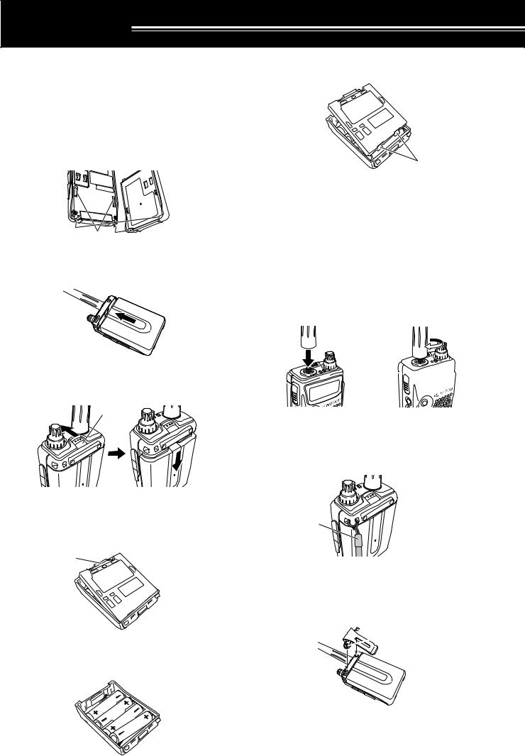
INSTALLING THE Li-ion BATTERY PACK
Note: Because the battery pack is provided uncharged, you must charge the battery pack before using it with the transceiver. To charge the battery pack, refer to “CHARGING THE Li-ion BATTERY PACK” {page 2}.
1Position the two grooves on the edge and two hooks at the bottom of the battery pack over the corresponding guides on the back of the transceiver.
Grooves
2Slide the battery pack along the back of the transceiver until the release latch on the top of the transceiver locks the battery pack in place.
3To remove the battery pack, push the release latch on top, then slide the battery pack down.
Latch
INSTALLING ALKALINE BATTERIES
1To open the battery case (BT-13), push the locking tab in, then pull the cover back.
Tab
2Insert (or remove) four AA (LR6) alkaline batteries.
•Be sure to match the battery polarities with those marked in the bottom of the battery case.
3Align the two tabs on the battery case cover, then close the cover until the locking tabs click.
Tabs
4To install the battery case onto (or remove it from) the transceiver, follow steps 1 to 3 of “INSTALLING THE Li-ion BATTERY PACK” {above}.
Note: When you use the alkaline batteries, access Menu No. 30 (BATTERY), then select “ALKALINE”. Otherwise, the battery remaining cannot be measured correctly {page 36}.
INSTALLING THE ANTENNA
Hold the base of the supplied antenna, then screw the antenna into the connector on the top panel of the transceiver until secure.
a 

ATTACHING THE HAND STRAP
If desired, you can attach the supplied hand strap to the transceiver.
Strap
INSTALLING THE BELT CLIP
You can install the supplied belt clip to the transceiver tightening the 2 supplied screws.
 Screws
1
1 PREPARATION
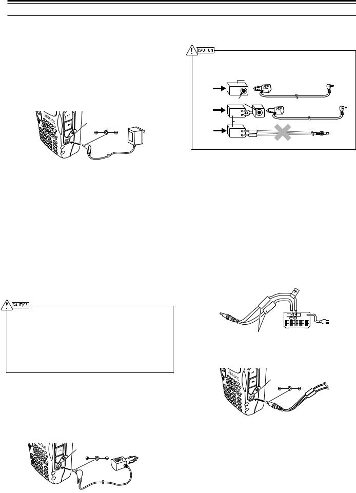
CHARGING THE Li-ion BATTERY PACK
The Li-ion battery pack can be charged after it has been installed onto the transceiver. The battery pack is provided uncharged for safety purposes.
1Confirm that the transceiver power is OFF.
•While charging the battery pack, leave the transceiver power OFF.
2Insert the charger plug into the DC IN jack of the transceiver.
DC IN jack
3Plug the charger into an AC wall outlet.
•Charging starts and 2 LEDs on the top panel lights orange.
4It takes approximately 6.5 hours to charge an empty PB-42L Li-ion battery pack. When charging completes, the LEDs unlight; remove the charger plug from the transceiver DC IN jack.
5Unplug the charger from the AC wall outlet.
Note:
If you turn the transceiver ON and press [F], [LOW/ BATT] while charging the battery pack, “CHARGING” appears. “STANDBY” appears when the charging completes.
The transceiver becomes warm while charging the battery pack.
If the charger plug is plugged into the DC IN jack before the battery pack is attached, turn the transceiver ON and then OFF again to initiate the charging.
Exceeding the specified charge period shortens the useful life of the Li-ion battery pack.
The provided charger is designed to charge only the provided PB-42L Li-ion battery pack. Charging other models of battery packs may damage the charger and battery pack.
Do not press [PTT] while charging.
The battery pack must be kept in cool and dry place.
Never leave the battery pack in the direct sun light.
CONNECTING TO A CIGARETTE LIGHTER SOCKET
To connect the transceiver to the cigarette lighter socket in your vehicle, use an optional PG-3J Cigarette Lighter cable.
DC IN jack
 DC 12 V
While the PG-3J is connected to the cigarette lighter plug, the transceiver automatically start charging the Li-ion battery pack (PB-42L). When you operate the transceiver, it charges the Li-ion battery pack in back
ground. If the transceiver is turned OFF, the 2 LEDs light orange while charging. When the charging completes, they turn OFF {above}.
To connect with an external 24 V power source via a DC-DC converter, only use the optional PG-3J Cigarette Lighter cable. Using the PG-2W DC cable in this situation may cause a fire.
|
|
DC-DC Converter |
24V |
12V |
PG-3J |
|
|
|
Socket |
|
24V |
12V |
PG-3J |
|
|
|
|
DC-DC Converter |
|
24V |
12V |
|
|
|
PG-2W
Note: If the input voltage exceeds approximately 16.5 V, warning beeps sound and “VOLTAGE ERROR” appears.
CONNECTING TO A REGULATED POWER SUPPLY
To connect the transceiver to an appropriate regulated power supply, use an optional PG-2W DC cable.
1Confirm that the power of both the transceiver and the power supply are OFF.
2Connect the optional PG-2W DC cable to the power supply; the red lead to the positive (+) terminal, and the black lead to the negative (–) terminal.
Fuses (4 A)
3Connect the barrel plug on the DC cable to the DC IN jack of the transceiver.
DC IN jack
If the transceiver is turned OFF while a regulated power supply is connected with the DC IN jack, it automatically initiates charging the Li-ion battery pack (PB-42L) {above}.
Note:
If the DC power supply voltage is below 12.0 V DC, you may not be able to charge the Li-ion battery pack (PB-42L).
The supply voltage must be between 12.0 V and 16.0 V to prevent damaging the transceiver. If input voltage exceeds approximately 16.5 V, warning beeps sound and “VOLTAGE
ERROR” appears. Remove the DC IN jack plug immediately.
If the DC power supply voltage is above 14.5 V DC and “H” (High Power) is selected, “H” icon blinks and the output power is reduced to “L” level (Low Power) automatically {page 41}.
2
YOUR FIRST QSO
FIRST QSO
Are you ready to give your transceiver a quick try? Reading this page should get your voice on the air right away. The instructions below are intended only for a quick guide. If you encounter problems or there is something you would like to know more, read the detailed explanations given later in this manual.
|
6 |
7 |
8 |
3 |
5 |
4 |
1 |
|
|
|
2 |
|
|
|
|
FM TRIBANDER TH-F6 |
|
qPress and hold [  ] (POWER) briefly to switch the transceiver power ON.
•A high pitched double beep sounds and then “KENWOOD” and “HELLO !!” appear momentarily. The various indicators and 2 frequencies appear on the LCD.
•The transceiver stores the parameters when it is turned OFF. It automatically recalls these parameters next time you turn the transceiver ON again.
wPress [A/B] to select the frequency band on top.
•Each time you press [A/B], the “s” icon moves, indicating which frequency band is currently selected for operation.
eTurn the VOL control clockwise to the 11 o’clock position.
rPress [BAND] until you select the amateur radio band you wish to operate.
tTurn the Tuning control to select the receive frequency.
•You may further turn the VOL control to adjust the volume level of the signal.
yTo transmit, hold the transceiver approximately 5 cm (2 inches) from your mouth.
uPress and hold the PTT switch, then speak in your normal tone of voice.
i Release the PTT switch to receive.
oRepeat steps y, u and i to continue communication.
3

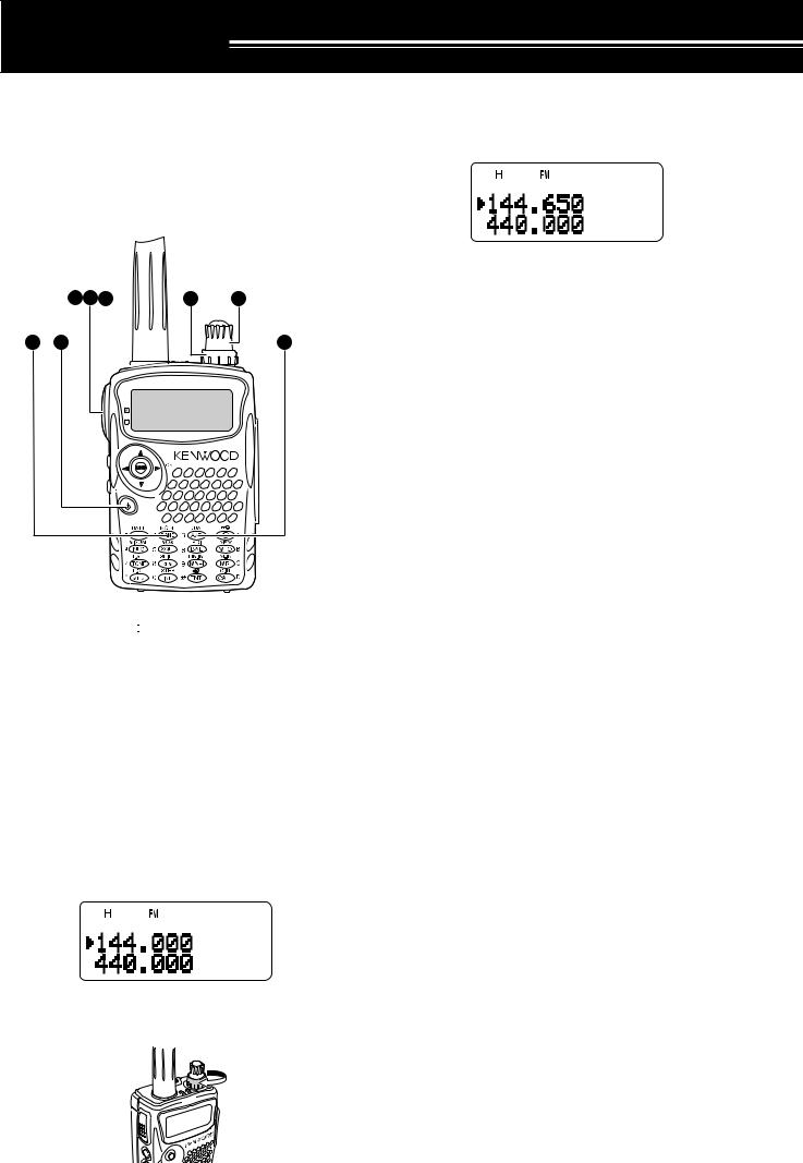
GETTING ACQUAINTED
KEYS AND CONTROLS
Antenna
 Tuning Control
 VOL Control
|
FM TRIBANDER TH-F6 |
PTT switch |
Display |
LAMP Key |
SP/MIC jack |
Multi-scroll |
|
Key |
Speaker/ Mic. |
MONI Key |
|
Power Switch |
DC IN jack |
|
|
|
Keypad |
Battery release
M
A/ B-band status LEDs
Green : Busy
Red : Transmitting
Orange: Charging
4
3 GETTING ACQUAINTED
DISPLAY
1 |
2 |
3 |
4 |
5 |
6 |
7 |
8 |
9 |
10 |
11 |
12 |
13 |
14 |
21 |
|
|
22 |
|
15 |
16 |
17 |
18 |
19 |
20 |
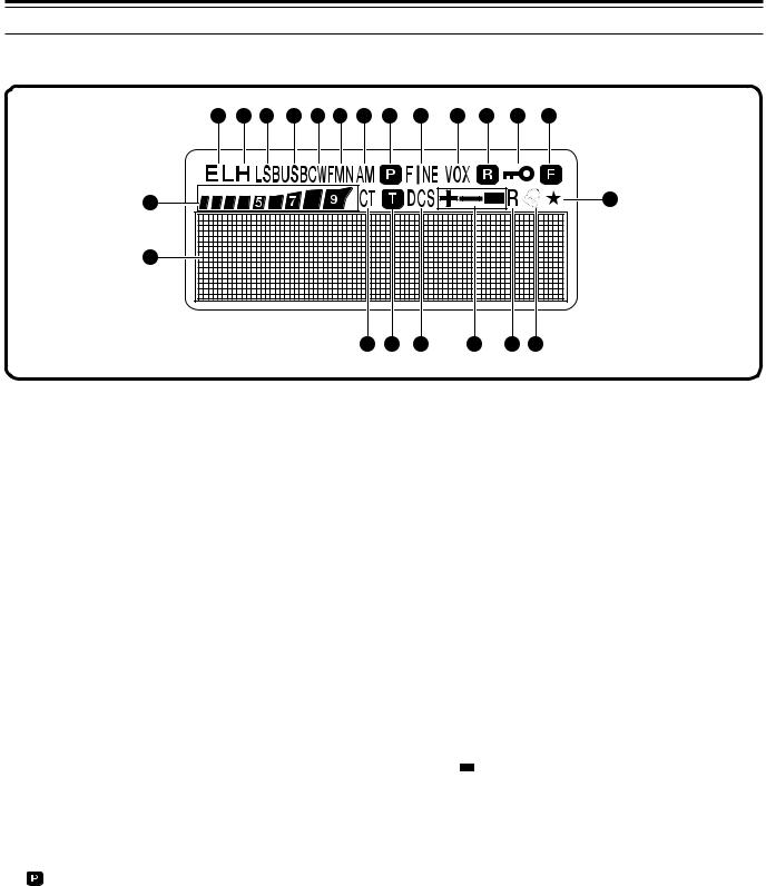
q EL
Appears when the transmit output power is set to Low (“L”) or Economic Low (“EL”) {pages 7, 41}.
w H
Appears when the transmit output power is set to High (“H”) {pages 7, 41}.
e LSB
Appears when lower side band (LSB) is selected for B-band {page 34}.
r USB
Appears when upper side band (USB) is selected for B-band {page 34}.
t CW
Appears when CW is selected for B-band {page 34}.
y WFMN
“WFM” appears when wide FM mode is selected {page 34}. “FM” appears when normal FM mode is selected. “FMN” appears when narrow FM mode is selected {page 39}.
u AM
“AM” appears when AM mode is selected {page 34}.
i
Appears when a Priority Scan is activated {page 25}.
o FINE
Appears when a Fine Tuning function is activated {page 35}.
!0VOX
Appears when the VOX function is activated {page 41}.
!1
Appears when the Automatic Simplex Check (ASC) is activated {page 14}.
!2
Appears when the Lock function is ON {page 38}.
!3
Appears when the function key is pressed.
!4


S-meter (RX) and relative RF power meter (TX).
!5CT
“CT” appears when the CTCSS function is activated {page 28}.
!6
Appears when the Tone function is activated {page 13}.
!7DCS
Appears when the DCS function is activated {page 29}.
!8+/ –/
Appears when the repeater shift function is activated {page 12}.
!9R
Appears when the Reverse function is activated {page 14}.
@0
Appears when the Tone Alert function is activated {page 40}.
@1
Appears when the displayed memory channel has been locked out {page 27}.
@2Dot-matrix display
76 x 16 dot-matrix display. It displays various information, such as the operating frequencies, menu settings, and etc.
5
3 GETTING ACQUAINTED
BASIC OPERATION |
|
• The higher the level, the stronger the signals |
|||||||||
SWITCHING POWER ON/ OFF |
|
must be, to receive. |
|||||||||
|
• 6 different levels can be set |
||||||||||
1 Press [ |
|
] (POWER) briefly to switch the |
|
||||||||
|
|
(-- -- -- -- --: level 0 ~ || || || || ||: level 5). |
|||||||||
|
|
||||||||||
|
|
||||||||||
transceiver power ON. |
3 |
Press [ |
] or [MNU] to store the new settings or |
||||||||
|
|
|
|
|
|
|
|
|
|||
• Upon power up, a high pitched double beep |
|
press [ |
] to cancel without changing the current |
||||||||
sounds, followed by the frequencies and other |
|
setting. |
|
||||||||
indicators. |
Note: When operating in USB, LSB and CW modes, the squelch |
||||||||||
|
|
|
|
|
|
|
|
|
|||
|
|
|
|
|
|
|
|
|
unmutes up to level 2. |
||
|
|
|
|
|
|
|
|
|
|
|
|
2To switch the transceiver OFF, press [  ] (POWER) again.
•When you turn the transceiver OFF, a low pitched double beep sounds.
•The transceiver stores the parameters when it is turned OFF. It recalls these parameters next time you turn the transceiver ON again.
ADJUSTING VOLUME
Turn the VOL control clockwise to increase the audio output level and counterclockwise to decrease the output level.
SELECTING A BAND
By default, two frequencies are displayed on the LCD. The frequency on top is called the A-band. The bottom frequency is called the B-band.
A-band
B-band
Press [A/B] to select the A-band or B-band for operation. Each time you press [A/B], the “s” icon moves, indicating which band is currently selected for operation. Usually, select the A-band to operate the amateur band and select the B-band to receive the various broadcasting stations, such as AM, FM, TV (audio only) or another amateur band {page 33}.
•If you are not receiving a signal, press and hold [MONI] to unmute the speaker, then adjust the VOL control to a comfortable audio output level.
ADJUSTING SQUELCH
The purpose of the Squelch is to mute the speaker when no signals are present. With the squelch level correctly set, you will hear sound only while actually receiving signals. The higher the selected squelch level, the stronger the signals must be, to receive. The appropriate squelch level depends on the ambient RF noise conditions. You can configure independent threshold squelch levels for the A-band and B-band.
1Press [SQL].
• The current squelch level appears.
2Turn the Tuning control or press [ ]/ [
]/ [ ] to adjust the level.
•Select the level at which the background noise is just eliminated when no signal is present.
MULTI-SCROLL KEY
This transceiver has a 4-way cursor key with a MENU (“MNU”) key in the center.
 /
/  keys
keys
The  /
/  keys function in the same way as the Tuning control. These keys change the frequencies, memory channels, and other selections.
Note: You can use the Tuning control in place of the  /
/  keys for most of the controls.
 / OK key
Press to move to the next step or complete the setting in various modes, such as Menu mode, CTCSS frequency selection, and DCS code selection.
 / ESC key
Press to move back or cancel the entry in various modes, such as Menu mode, CTCSS frequency selection, and direct frequency entry.
MNU key
Press to enter the Menu mode.
In Menu mode, you can select the desired menu number by turning the Tuning control or pressing [ ]/ [
]/ [ ]. It also functions as [OK] key.
6

3 GETTING ACQUAINTED
TRANSMITTING
1To transmit, hold the transceiver approximately 5 cm (2 inches) from your mouth, then press and hold the PTT switch and speak into the microphone in your normal tone of voice.
•The status LED on the top panel lights red and bar-graph meter appears.
•If you press [PTT] while you are outside of the transmission coverage, a high pitched error beep sounds.
2 When you finish speaking, release the PTT switch.
Note: If you transmit continuously for more than 10 minutes, the internal time-out timer generates a warning beep and the transceiver stops transmitting. In this case, release the PTT switch and let the transceiver cool down for a while, then press the PTT switch again to resume transmitting {pages 40, 51}.
■Selecting Output Power
Selecting lower transmission power is the best way to reduce the battery consumption, if communication is still reliable. You can configure different power levels for transmission {page 41}.
Press [LOW].
•Each time you press [LOW], the indicator cycles between “H” (high), “L” (low), and “EL” (economic low).
Note:
You can store different output power setting for the A and B- band.
When you change the output power, it is reflected to all available amateur bands for A or B-band.
SELECTING A FREQUENCY
■VFO Mode
This is the basic mode for changing the operating frequency. Turn the Tuning control clockwise to increase the frequency. Turn the Tuning control counterclockwise to decrease the frequency. Or, press [ ]/ [
]/ [ ] to change the frequency.
■MHz Mode
If the desired operating frequency is far away from the current frequency, it is quicker to use the MHz tuning mode.
To adjust the MHz digit:
1Press [MHz].
• A MHz digit blinks.
2Turn the Tuning control or press [ ]/ [
]/ [ ] to select the desired MHz digit.
3After selecting the desired MHz digit, press [MHz] to exit the mode and return to normal VFO mode {above}.
4You may further adjust the frequency using the Tuning control or [ ]/ [
]/ [ ].
].
Note: MHz mode does not function in AM band.
■Direct Frequency Entry
In addition to turn the Tuning control or press
[ ]/ [ ], there is another way of selecting the frequency. When the desired frequency is far away from the current frequency, you can directly enter a frequency from the numeric keypad.
1Press [VFO].
•You must be in the VFO mode to make the direct frequency entry.
2Press [ENT].
•“– – – – – –” appears.
3Press the numeric keys ([0] to [9]) to enter your desired frequency. [MHz] can be used to complete the MHz digits entry.
•Pressing [ENT] fills the remaining digits (the digits you did not enter) with 0 and completes the entry.
•To select 145.000 MHz for example, press [1], [4], [5] then press [ENT] to complete the entry.
•If you want to revise the MHz digits only, press [VFO] in place of [ENT].
7

3 GETTING ACQUAINTED
Example 1 (100 MHz < f < 1000 MHz)
To enter 438.320 MHz:
Key in |
Display |
[ENT] |
– – – – – – |
[4], [3], [8] |
4 3 8. – – – |
[3], [2], [0] |
4 3 8. 3 2 0 |
Note: You do not have to press [MHz] when you are entering 3-digit MHz number.
Example 2
To enter 439.000 MHz:
Key in |
Display |
[ENT] |
– – – – – – |
[4], [3], [9] |
4 3 9. – – – |
[ENT] |
4 3 9. 0 0 0 |
Example 3
To revise 144.650 MHz to 145.650 MHz:
Key in |
Display |
|
|
||
|
1 4 |
4. |
6 |
5 |
0 |
[ENT] |
– – – |
– – – |
|||
[1], [4], [5] |
1 4 5. |
– – – |
|||
[VFO] |
1 4 5. |
6 5 0 |
|||
Example 4 (f > 1000 MHz)
To enter 1250.500 MHz (B-band only):
Key in |
Display |
|
[ENT] |
– – – – – – |
|
[1], [2], [5], [0] |
12 5 0. |
– – – |
[5] |
12 5 0. |
5 – – |
[ENT] |
12 5 0. |
5 0 0 |
Example 5 (f < 100 MHz)
To enter 10.500 MHz (B-band only):
Key in |
Display |
|
|
||
[ENT] |
– – – – – – |
|
|||
[1], [0] |
1 0 |
– |
– – – |
|
|
[MHz] |
1 |
0. |
– – – |
|
|
[5] |
1 |
0. |
5 |
– – |
|
[ENT] |
1 |
0. |
5 |
0 0 |
0 |
Note: When pressing the last [ENT], the Fine Tuning function is automatically activated for 10.5000 MHz.
Example 6
To enter 810 kHz (B-band only):
Key in |
Display |
|
[ENT] |
– – – |
– – – |
[0] |
0 – – |
– – – |
[MHz] |
0. – – – |
|
[8], [1], [0] |
0. 8 1 0 |
|
Note:
If the entered frequency does not match the current frequency step size, the frequency is automatically rounded down to the next available frequency.
When the desired frequency cannot be entered exactly, check whether the Fine Tuning function is ON or not {page 35}, and then confirm the frequency step size
{page 37}.
Some frequency ranges are blocked, due to government regulations. Refer to the specifications {pages 53, 54} for the TX/ RX coverage.
If you turn the Tuning control or press [ ]/ [
]/ [  ] while entering the frequency, the transceiver clears the entry and recovers the previous frequency and mode.
8
MENU SETUP
WHAT IS A MENU?
Many functions on this transceiver are selected or configured via a software-controlled Menu, rather than through the physical controls of the transceiver. Once familiar with the Menu system, you will appreciate the versatility it offers. You can customize the various timings, settings, and programming functions on this transceiver to meet your needs without using many controls and switches.
MENU ACCESS
1Press [MNU].
•The Menu No. and setting appear on the display, along with a brief explanation of the Menu No.
2Turn the Tuning control or press [ ]/ [
]/ [ ] to select your desired Menu No.
•As you change the Menu No., a brief explanation of each Menu No. appears.
3Press [ ] or [MNU] to configure the parameter of the currently selected Menu No.
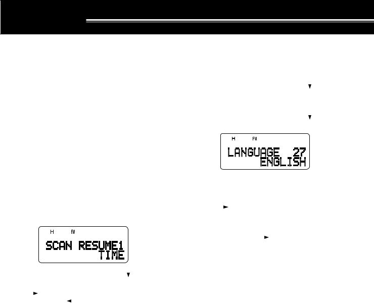
SELECTING A MENU LANGUAGE
You can select either English or Japanese (Katakana) for the menu description. To switch the language:
1Press [MNU].
2Turn the Tuning control or press [ ]/ [ ] to select Menu No. 27.
3Press [ ] or [MNU].
4Turn the Tuning control or press [ ]/ [ ] to select either “ENGLISH” or “JAPANESE”.
5Press [ ] or [MNU] to store the setting. Otherwise, press [
 ] or [PTT] to cancel.
•When you select “JAPANESE” in step 3 and press [ ] or [MNU], all Menu explanations are displayed in Japanese (Katakana). To return to English mode, repeat step 1, 2 and 3 {above} to access Menu No. 27, then select
“ENGLISH”. Press [ ] or [MNU] to display the Menu mode in English.
Note: The menu language selection does not affect any other modes, such as memory name {page 17} or DTMF name {page 31}.
4Turn the Tuning control or press [ ]/ [ ] to select your desired parameter.
5Press [ ] or [MNU] to store the setting.
Otherwise, press [ ] or [PTT] to cancel.
MENU FUNCTION LIST
On the Display |
Menu |
Function |
Selections |
Default |
Ref. |
|
No. |
Page |
|||||
|
|
|
|
|||
|
|
Scan resume method |
|
|
|
|
SCAN RESUME |
1 |
TIME: Time-Operated mode |
TIME/ CARRIER/ |
TIME |
27 |
|
CARRIER: Carrier-Operated mode |
SEEK |
|||||
|
|
|
|
|||
|
|
SEEK: Seek and stop mode |
|
|
|
|
|
|
|
|
|
|
|
M.GRP LINK |
2 |
Memory Group Link configuration |
0 1 2 3 4 5 6 7 |
No Links |
24 |
|
|
|
|
|
|
|
|
MR METHOD |
3 |
Memory Recall condition |
ALL BANDS/ |
ALL |
16 |
|
CURRENT BAND |
BANDS |
|||||
|
|
|
|
|||
|
|
|
|
|
|
|
PROG VFO |
4 |
Programmable VFO frequency range |
— |
See |
39 |
|
Reference |
||||||
(A-band only) |
||||||
|
|
|
Page |
|
||
|
|
|
|
|
||
|
|
|
|
|
|
|
AUTO OFFSET |
5 |
Auto Repeater Offset function |
ON/ OFF |
ON |
13 |
|
|
|
|
|
|
|
|
|
|
|
0.00 ~ 59.95 MHz |
See |
|
|
OFFSET |
6 |
Repeater offset frequency |
in steps of |
Reference |
12 |
|
|
|
|
0.05 MHz |
Page |
|
|
|
|
|
|
|
|
|
TUNE ENABLE |
7 |
Permit use of the Tuning control when the keys |
ON/ OFF |
OFF |
38 |
|
are locked |
||||||
|
|
|
|
|
||
|
|
|
|
|
|
|
TX INHIBIT |
8 |
Inhibit the transmission |
ON/ OFF |
OFF |
40 |
|
|
|
|
|
|
|
|
SP/MIC JACK |
9 |
Select the SP/MIC jack function |
SP/MIC / TNC/ PC |
SP/MIC |
45 |
|
46 |
||||||
|
|
|
|
|
||
|
|
|
|
|
|
9

4 MENU SETUP
On the Display |
Menu |
Function |
Selections |
Default |
Ref. |
|
No. |
Page |
|||||
|
|
|
|
|||
DTMF STORE |
10 |
Store DTMF numbers in DTMF memories |
— |
No Data |
31 |
|
|
|
|
|
|
|
|
DTMF SPD |
11 |
DTMF tone transmission speed |
FAST/ SLOW |
FAST |
32 |
|
|
|
|
|
|
|
|
DTMF HOLD |
12 |
Hold the transmission for 2 seconds between |
ON/ OFF |
OFF |
31 |
|
DTMF key entries |
||||||
|
|
|
|
|
||
|
|
|
|
|
|
|
|
|
The pause duration while transmitting DTMF |
100/ 250/ 500/ |
|
|
|
DTMF PAUSE |
13 |
750/ 1000/ 1500/ |
500 ms |
32 |
||
tones |
||||||
|
|
2000 ms |
|
|
||
|
|
|
|
|
||
|
|
|
|
|
|
|
DTMF LOCK |
14 |
Disable DTMF transmission with keys |
ON/ OFF |
OFF |
32 |
|
|
|
|
|
|
|
|
PWR-ON MSG |
15 |
Power-on message |
8 characters |
HELLO !! |
39 |
|
|
|
|
|
|
|
|
CONTRAST |
16 |
LCD display contrast |
1 ~ 16 |
8 |
37 |
|
1: minimum ~ 16: maximum |
||||||
|
|
|
|
|
||
|
|
|
|
|
|
|
|
|
|
OFF/ 0.2/ 0.4/ 0.6/ |
|
|
|
BAT SAVER |
17 |
Battery saver receiver shut-off period |
0.8/ 1.0/ 2.0/ 3.0/ |
1.0 sec. |
37 |
|
|
|
|
4.0/ 5.0 sec. |
|
|
|
|
|
|
|
|
|
|
APO |
18 |
Automatic Power Off function |
OFF/ 30/ 60 min. |
30 min. |
36 |
|
|
|
|
|
|
|
|
KEY BEEP |
19 |
Beep function |
ON/ OFF |
ON |
37 |
|
|
|
|
|
|
|
|
VOXonBUSY |
20 |
Allow VOX transmission when the receiver is |
ON/ OFF |
OFF |
42 |
|
busy |
||||||
|
|
|
|
|
||
|
|
|
|
|
|
|
VOX GAIN |
21 |
Set the VOX gain sensitivity |
0 ~ 9 |
4 |
41 |
|
0: least sentisive ~ 9: most sensitive |
||||||
|
|
|
|
|
||
|
|
|
|
|
|
|
|
|
|
250/ 500/ 750/ |
|
|
|
VOX DELAY |
22 |
Adjust the VOX delay time |
1000/ 1500/ 2000/ |
500 ms |
41 |
|
|
|
|
3000 ms |
|
|
|
|
|
|
|
|
|
|
|
|
|
|
CALL |
|
|
CALL KEY |
23 |
Select a function for the CALL key |
CALL/ 1750 Hz |
(TH-F6A) |
19 |
|
1750 Hz |
||||||
|
|
|
|
|
||
|
|
|
|
(TH-F7E) |
|
|
|
|
|
|
|
|
|
1750 HOLD |
24 |
Hold the TX status when a 1750 Hz tone is |
ON/ OFF |
OFF |
13 |
|
transmitted |
||||||
|
|
|
|
|
||
|
|
|
|
|
|
|
BEAT SHIFT |
25 |
Shift the internal CPU clock frequency |
ON/ OFF |
OFF |
37 |
|
|
|
|
|
|
|
|
BAR ANT |
26 |
Enable an internal bar antenna below 10.1 MHz |
ENABLED/ |
ENABLED |
34 |
|
DISABLED |
||||||
|
|
|
|
|
||
|
|
|
|
|
|
|
LANGUAGE |
27 |
Select the menu language |
ENGLISH/ |
ENGLISH |
9 |
|
JAPANESE |
||||||
|
|
|
|
|
||
|
|
|
|
|
|
|
PACKET |
28 |
Select an external TNC packet speed |
1200/ 9600 bps |
1200 bps |
45 |
|
|
|
|
|
|
|
|
FM NARROW |
29 |
FM narrow band operation |
ON/ OFF |
OFF |
39 |
|
|
|
|
|
|
|
|
BATTERY |
30 |
Select a battery type |
LITHIUM/ |
LITHIUM |
36 |
|
ALKALINE |
||||||
|
|
|
|
|
||
|
|
|
|
|
|
|
|
|
|
NO/ VFO RESET/ |
|
|
|
RESET? |
31 |
Select a reset mode |
MENU RESET/ |
NO |
50 |
|
|
|
|
FULL RESET |
|
|
|
|
|
|
|
|
|
10

4 MENU SETUP
ALPHABETICAL FUNCTION LIST
On the Display |
Menu No. |
Selections |
Default |
Ref. Page |
|
|
|
|
|
|
|
APO |
18 |
OFF/ 30/ 60 minutes |
30 min. |
36 |
|
|
|
|
|
|
|
AUTO OFFSET |
5 |
ON/ OFF |
ON |
13 |
|
|
|
|
|
|
|
BAR ANT |
26 |
ENABLED/ DISABLED |
ENABLED |
34 |
|
|
|
|
|
|
|
BATTERY |
30 |
LITHIUM/ ALKALINE |
LITHIUM |
36 |
|
|
|
|
|
|
|
BAT SAVER |
17 |
OFF/ 0.2/ 0.4/ 0.6/ 0.8/ 1.0/ 2.0/ 3.0/ 4.0/ 5.0 sec. |
1.0 sec. |
37 |
|
|
|
|
|
|
|
BEAT SHIFT |
25 |
ON/ OFF |
OFF |
37 |
|
|
|
|
|
|
|
|
|
|
CALL |
|
|
CALL KEY |
23 |
CALL/ 1750 Hz |
(TH-F7E)/ |
19 |
|
1750 Hz |
|||||
|
|
|
|
||
|
|
|
(TH-F6A) |
|
|
|
|
|
|
|
|
CONTRAST |
16 |
1 ~ 16 |
8 |
37 |
|
|
|
|
|
|
|
DTMF HOLD |
12 |
ON/ OFF |
OFF |
31 |
|
|
|
|
|
|
|
DTMF LOCK |
14 |
ON/ OFF |
OFF |
32 |
|
|
|
|
|
|
|
DTMF PAUSE |
13 |
100/ 250/ 500/ 750/ 1000/ 1500/ 2000 ms |
500 ms |
32 |
|
|
|
|
|
|
|
DTMF SPD |
11 |
FAST/ SLOW |
FAST |
32 |
|
|
|
|
|
|
|
DTMF STORE |
10 |
— |
No Data |
31 |
|
|
|
|
|
|
|
FM NARROW |
29 |
ON/ OFF |
OFF |
39 |
|
|
|
|
|
|
|
KEY BEEP |
19 |
ON/ OFF |
ON |
37 |
|
|
|
|
|
|
|
LANGUAGE |
27 |
ENGLISH/ JAPANESE |
ENGLISH |
9 |
|
|
|
|
|
|
|
MR METHOD |
3 |
ALL BANDS/ CURRENT BAND |
ALL |
16 |
|
BANDS |
|||||
|
|
|
|
||
|
|
|
|
|
|
M.GRP LINK |
2 |
0 1 2 3 4 5 6 7 |
No Links |
24 |
|
|
|
|
|
|
|
|
|
|
See |
|
|
OFFSET |
6 |
0.00 ~ 59.95 MHz in steps of 0.05 MHz |
Reference |
12 |
|
|
|
|
Page |
|
|
|
|
|
|
|
|
PACKET |
28 |
1200/ 9600 bps |
1200 bps |
45 |
|
|
|
|
|
|
|
PROG VFO |
4 |
— |
— |
39 |
|
|
|
|
|
|
|
PWR-ON MSG |
15 |
8 characters |
HELLO !! |
39 |
|
|
|
|
|
|
|
RESET? |
31 |
NO/ VFO RESET/ MENU RESET/ FULL RESET |
NO |
50 |
|
|
|
|
|
|
|
SCAN RESUME |
1 |
TIME/ CARRIER/ SEEK |
TIME |
27 |
|
|
|
|
|
|
|
SP/MIC JACK |
9 |
SP/MIC / TNC/ PC |
SP/MIC |
45, 46 |
|
|
|
|
|
|
|
TUNE ENABLE |
7 |
ON/ OFF |
OFF |
38 |
|
|
|
|
|
|
|
TX INHIBIT |
8 |
ON/ OFF |
OFF |
40 |
|
|
|
|
|
|
|
VOX DELAY |
22 |
250/ 500/ 750/ 1000/ 1500/ 2000/ 3000 ms |
500 ms |
41 |
|
|
|
|
|
|
|
VOX GAIN |
21 |
0 ~ 9 |
4 |
41 |
|
|
|
|
|
|
|
VOXonBUSY |
20 |
ON/ OFF |
OFF |
42 |
|
|
|
|
|
|
|
1750 HOLD |
24 |
ON/ OFF |
OFF |
13 |
|
|
|
|
|
|
11
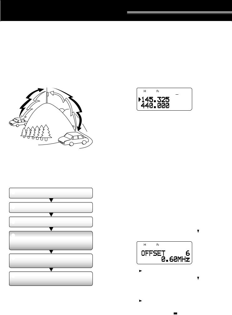
OPERATING THROUGH REPEATERS
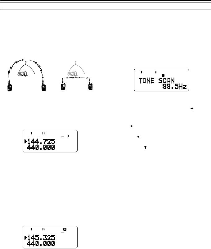
Repeaters, which are often installed and maintained by radio clubs, are usually located on mountain tops or other elevated locations. Generally they operate at higher ERP (Effective Radiated Power) than a typical station. This combination of elevation and high ERP allows communications over much greater distances than communications without using repeaters.
Most repeaters use a receive and transmit frequency pair with a standard or non-standard offset (odd-split). In addition, some repeaters must receive a tone from the transceiver to allow it to access. For details, consult your local repeater reference.
TX: 144.725 MHz
TX tone: 88.5 Hz
RX: 145.325 MHz TX: 144.725 MHz
TX tone: 88.5 Hz
RX: 145.325 MHz
OFFSET PROGRAMMING FLOW
q Select a band.
w Select a receive frequency.
e Select an offset direction.
rSelect an offset frequency.
(only when programming odd-split repeater frequencies)
tActivate the Tone function. (If necessary)
ySelect a tone frequency. (If necessary)
If you store the above data in a memory channel, you need not reprogram every time. See “MEMORY CHANNELS” {page 15}.
PROGRAMMING OFFSET
First select an amateur radio repeater downlink frequency on the A-band or B-band as described in “SELECTING A FREQUENCY” {page 7}.
■Selecting Offset Direction
Select whether the transmit frequency will be higher (+) or lower (–) than the receive frequency.
Press [F], [REV] to select the offset direction.
•“+” or “–” appears, indicating which offset direction is selected.
•To program –7.6 MHz offset on the TH-F7E (430 MHz only), repeatedly press [F], [REV] until “ ” appears.
If the offset transmit frequency falls outside the allowable range, transmitting is inhibited. In this case, adjust the receive frequency so that the transmit frequency is within the band limits.
Note: While using an odd-split memory channel or transmitting, you cannot change the offset direction.
■Selecting Offset Frequency
To access a repeater which requires an odd-split frequency pair, change the offset frequency from the default which is used by most repeaters. The default offset frequency on the 2 m band is
600 kHz (all models); the default on the 70 cm band is 5.0 MHz (TH-F6A) or 1.6 MHz (TH-F7E); the default on the 1.25 m band is 1.6 MHz (TH-F6A).
1Press [BAND] to select an amateur radio band you want to change the offset frequency.
2Press [MNU].
3Turn the Tuning control or press [ ]/ [ ] to select Menu No. 6 (OFFSET).
4Press [ ] or [MNU].
5Turn the Tuning control or press [ ]/ [ ] to select the appropriate offset frequency.
• The selectable range is from 0.00 MHz to 59.95 MHz in steps of 50 kHz.
6 Press [ ] or [MNU] to store the setting. Otherwise, press [PTT] to cancel.
TH-F7E only: If you have selected “ ” for the offset direction, you cannot change the default (–7.6 MHz) offset frequency.
Note: After changing the offset frequency, the new offset frequency will also be used by Automatic Repeater Offset.
12
5 OPERATING THROUGH REPEATERS
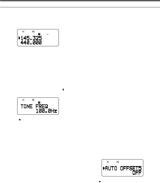
■Activating Tone Function
Press [TONE] to switch the Tone function ON (or OFF).
• “ ” appears when the Tone function is ON.
Note: You cannot use the Tone and CTCSS/ DCS functions at the same time. Switching the Tone function ON after activating the CTCSS/ DCS deactivates the CTCSS/ DCS function.
TH-F7E only: When you access repeaters that require 1750 Hz tones, you need not activate the Tone function. Press [CALL] without pressing the PTT switch to transmit a 1750 Hz tone (default setting).
■Selecting a Tone Frequency
1While the Tone function is ON, press [F],
[TONE].
2Turn the Tuning control or press [ ]/ [ ] to select the desired tone frequency.
3Press [ ] or [MNU] to complete the setting. Otherwise, press [PTT] to cancel.
Available Tone Frequencies
No. |
Freq. |
No. |
Freq. |
No. |
Freq. |
No. |
Freq. |
|
(Hz) |
(Hz) |
(Hz) |
(Hz) |
|||||
|
|
|
|
|||||
01 |
67.0 |
12 |
97.4 |
23 |
141.3 |
34 |
206.5 |
|
|
|
|
|
|
|
|
|
|
02 |
69.3 |
13 |
100.0 |
24 |
146.2 |
35 |
210.7 |
|
|
|
|
|
|
|
|
|
|
03 |
71.9 |
14 |
103.5 |
25 |
151.4 |
36 |
218.1 |
|
|
|
|
|
|
|
|
|
|
04 |
74.4 |
15 |
107.2 |
26 |
156.7 |
37 |
225.7 |
|
|
|
|
|
|
|
|
|
|
05 |
77.0 |
16 |
110.9 |
27 |
162.2 |
38 |
229.1 |
|
|
|
|
|
|
|
|
|
|
06 |
79.7 |
17 |
114.8 |
28 |
167.9 |
39 |
233.6 |
|
|
|
|
|
|
|
|
|
|
07 |
82.5 |
18 |
118.8 |
29 |
173.8 |
40 |
241.8 |
|
|
|
|
|
|
|
|
|
|
08 |
85.4 |
19 |
123.0 |
30 |
179.9 |
41 |
250.3 |
|
|
|
|
|
|
|
|
|
|
09 |
88.5 |
20 |
127.3 |
31 |
186.2 |
42 |
254.1 |
|
|
|
|
|
|
|
|
|
|
10 |
91.5 |
21 |
131.8 |
32 |
192.8 |
|
|
|
|
|
|
|
|
|
|
|
|
11 |
94.8 |
22 |
136.5 |
33 |
203.5 |
|
|
|
|
|
|
|
|
|
|
|
Note: 42 different tones are available for the transceiver. These 42 tones includes 37 EIA standard tones and 5 non-standard tones.
TH-F7E only:
To transmit a 1750 Hz tone, simply press [CALL] without pressing the PTT switch (default setting). Release [CALL] to quit transmitting. You can also make the transceiver remain in the transmit mode for 2 seconds after releasing [CALL]; a
1750 Hz tone is not continuously transmitted. Access Menu
No. 24 (1750 HOLD) and select “ON”.
If you desire to assign [CALL] for recalling the Call channel in place of transmitting the 1750 Hz tone, access Menu No. 23 (CALL KEY) and select “CALL”.
AUTOMATIC REPEATER OFFSET
This function automatically selects an offset direction, according to the frequency that you select on the
2 m and 1.25 m (TH-F6A only) bands. The transceiver is programmed for offset direction as shown below. To obtain an up-to-date band plan for repeater offset direction, contact your national Amateur Radio association.
TH-F6A (U.S.A. and Canada)
This complies with the standard ARRL band plan.
144.0 |
145.5 |
146.4 |
147.0 |
147.6 |
|
|
||||||||||
145.1 |
146.0 |
146.6 |
|
147.4 |
|
148.0 MHz |
||||||||||
|
|
|
|
|
|
|
|
|
|
|
|
|
|
|
|
|
|
S |
– |
S |
|
+ |
S |
– |
+ |
|
S |
– |
|
||||
|
|
|
|
|
|
|
|
|
|
|
|
|
|
|
|
|
|
S: Simplex |
|
|
|
|
|
|
|
|
|
|
|
|
|
||
222.0 |
|
|
|
|
|
223.920 |
|
|
|
225.0 MHz |
||||||
|
|
|
|
S |
|
|
|
|
|
|
– |
|
|
|
||
|
|
|
|
|
|
|
|
|
|
|
|
|
|
|
||
|
S: Simplex |
|
|
|
|
|
|
|
|
|
|
|
|
|
||
TH-F7E (Europe/ Others) |
|
|
|
|
|
|
|
|
|
|
|
|||||
144.0 |
|
|
|
|
|
145.6 |
|
145.8 146.0 MHz |
||||||||
|
|
|
|
|
|
|
|
|
|
|
|
|
|
|||
|
|
|
|
S |
|
|
|
|
|
– |
|
S |
|
|
||
|
|
|
|
|
|
|
|
|
|
|
|
|
|
|
||
|
S: Simplex |
|
|
|
|
|
|
|
|
|
|
|
|
|
||
Note: Automatic Repeater Offset does not function when Reverse is
ON. However, pressing [REV] after Automatic Repeater Offset has selected an offset (split) status, exchanges the receive and transmit frequencies.
1Press [MNU].
2Turn the Tuning control or press [ ]/ [
]/ [ ] to select Menu No. 5 (AUTO OFFSET).
3Press [ ] or [MNU].
4Turn the Tuning control or press [ ]/ [
]/ [ ] switch the function ON or OFF.
5 Press [ ] or [MNU] to store the setting. Otherwise, press [PTT] to cancel.
Note: If you select the frequency within the amateur radio band on the B-band, the Automatic Repeater Offset function is also activated in any modes.
13
5 OPERATING THROUGH REPEATERS
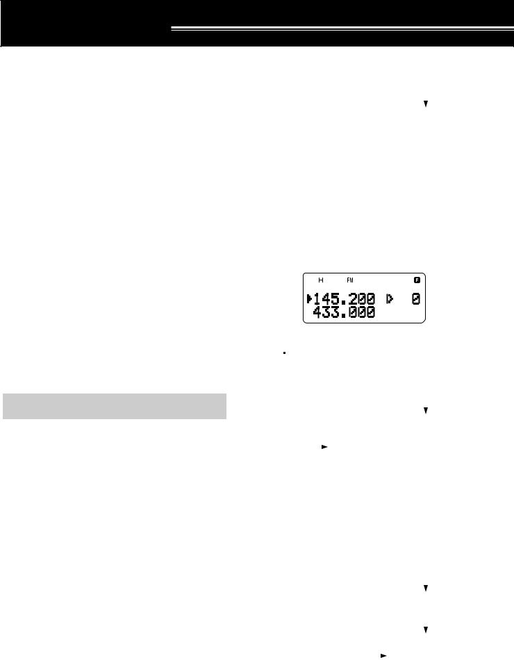
REVERSE FUNCTION
The reverse function exchanges a separate receive and transmit frequency. So, while using a repeater, you can manually check the strength of a signal that you receive directly from the other station. If the station’s signal is strong, both stations should move to a simplex frequency and free up the repeater.
|
|
|
MHz |
325 |
|
|
|
|
145 |
|
|
|
|
. |
144 |
. |
725 |
|
MHz |
|
|
144.725 MHz |
TONE FREQ. ID SCAN
This function scans through all tone frequencies to identify the incoming tone frequency on a received signal. You may use the function to find which tone frequency is required by accessing your local repeater.
1While the Tone function is ON, press [F], [TONE] (1 s) to start the Tone Freq. ID scan.
•When the transceiver receives the signal, the scan starts.
TX: 144.725 MHz TX: 144.725 MHz TX: 144.725 MHz TX: 145.325 MHz RX: 145.325 MHz RX: 145.325 MHz RX: 145.325 MHz RX: 144.725 MHz
To swap the transmit and receive frequencies:
Press [REV] to switch the Reverse function ON (or OFF).
•“R” appears when the function is ON.
Note: You can turn the Reverse function ON when you are operating in Simplex mode. However, it does not change the TX/ RX frequency.
AUTOMATIC SIMPLEX CHECK (ASC)
While using a repeater, the ASC function periodically checks the strength of a signal that you are receiving directly from the other station. If the station’s signal is strong enough to allow direct contact without a repeater, “ ” indicator on the display starts blinking.
Press [REV] (1 s) to switch the function ON.
•“ ” appears when the function is ON.
•While direct contact is possible, “ ” blinks.
•To quit the function, press [REV].
Note:
Pressing the PTT switch causes “  ” icon to quit blinking.
ASC can be activated while operating in Simplex mode.
However, it does not change the TX/ RX frequencies.
ASC does not function while scanning.
Activating ASC while using Reverse switches Reverse OFF.
If you recall a memory channel or the Call channel that contains a Reverse ON status, ASC is switched OFF.
ASC causes received audio to be momentarily intermitted every
3 seconds.
ASC does not function when the band is not selected for operation.
•To reverse the scan direction, turn the Tuning control or press [ ]/ [
]/ [ ].
].
• To quit the function, press [PTT] or [ ].
•When the tone frequency is identified, a beep sounds and the identified frequency appears.
2 Press [ ] to program the identified frequency in place of the current tone frequency.
• Press [ ] if you do not want to program the identified frequency.
•Press [ ]/ [ ] while the identified frequency is blinking, to resume scanning.
Note: Some repeaters do not re-transmit the access tone in the downlink signal. In this case, check the other station’s uplink signal to detect the repeater access tone.
14
MEMORY CHANNELS
In memory channels, you can store frequencies and related data that you often use. Then you need not reprogram those data every time. You can quickly recall a programmed channel through simple operation. A total of 400 memory channels are available for storing the frequencies, modes and other operating conditions of the A and B-bands.
SIMPLEX & REPEATER OR ODD-SPLIT MEMORY CHANNEL?
You can use each memory channel as a simplex & repeater channel or an odd-split channel. Store only one frequency to use as a simplex & repeater channel or two separate frequencies to use as an odd-split channel. Select either application for each channel depending on the operations you have in mind.
Simplex & repeater channels allow:
•Simplex frequency operation
•Repeater operation with a standard offset (if an offset direction is stored)
Odd-split channels allow:
•Repeater operation with a non-standard offset
Note: Not only can you store data in memory channels, but you can also overwrite existing data with new data.
The data listed below can be stored in each memory channel:
Parameter |
|
Simplex & |
Odd-Split |
|
Repeater |
||
|
|
|
|
|
|
|
|
Receive frequency |
|
Yes |
Yes |
|
|
|
|
Transmit frequency |
|
Yes |
|
|
|
||
|
|
|
|
Tone frequency |
|
Yes |
Yes |
|
|
|
|
Tone ON |
|
Yes |
Yes |
|
|
|
|
CTCSS frequency |
|
Yes |
Yes |
|
|
|
|
CTCSS ON |
|
Yes |
Yes |
|
|
|
|
DCS code |
|
Yes |
Yes |
|
|
|
|
DCS ON |
|
Yes |
Yes |
|
|
|
|
Offset direction |
|
Yes |
N/A |
|
|
|
|
Offset frequency |
|
Yes |
N/A |
|
|
|
|
Reverse ON |
|
Yes |
N/A |
|
|
|
|
Frequency step size |
|
Yes |
Yes |
|
|
|
|
Memory channel lockout |
|
Yes |
Yes |
|
|
|
|
Memory channel name |
|
Yes |
Yes |
|
|
|
|
FINE tuning ON |
|
Yes |
Yes |
|
|
|
|
Mode selection |
|
Yes |
Yes |
|
|
|
|
Yes: Can be stored in memory. |
|
|
|
N/A: Cannot be stored in memory. |
|
|
|
Note: The transmit frequency must be on the same band as the receive frequency band (Odd-split channel).
STORING SIMPLEX FREQUENCIES OR STANDARD REPEATER FREQUENCIES
1Press [VFO].
2Turn the Tuning control or press [ ]/ [ ] to select your desired frequency in the amateur radio bands.
•You can also directly enter desired frequency using the keypad {page 7}.
3If storing a standard repeater frequency, select the following data:
•Offset direction {page 12}
•Tone function, if necessary {page 13}
•CTCSS/ DCS function, if necessary {pages 28, 29}
If storing a simplex frequency, you may select other related data (CTCSS or DCS settings, etc.).
4 Press [F].
•A memory channel number appears and blinks.
•“
 ” indicates the current channel is empty; “
 ” appears if the channel contains data.
•Memory channel number L0/U0 ~ L9/U9 {page 23}, I–0 ~ I–9 {page 20}, and Pr1 and Pr2 {page 25} are reserved for other functions.
5Turn the Tuning control or press [ ]/ [ ] to select the memory channel in which you want to store the data.
6Press [MR] ([ ] or [MNU]) to store the data to the channel.
STORING ODD-SPLIT REPEATER FREQUENCIES
Some repeaters use a receive and transmit frequency pair with a non-standard offset. If you store two separate frequencies in a memory channel, you can operate on those repeaters without programming the offset frequency and direction.
1Store the desired receive frequency and related data by the procedure given for simplex or standard repeater frequencies {above}.
2Turn the Tuning control or press [ ]/ [ ] to select the desired transmit frequency.
3Press [F].
4Turn the Tuning control or press [ ]/ [ ] to select the memory channel you programmed in step 1.
5 Press [PTT]+[MR] ([PTT]+[ ] or [PTT]+[MNU]).
•The transmit frequency is stored in the memory channel.
Note:
When you recall an odd-split memory channel, “+” and “–” appear on the display. To confirm the transmit frequency, press [REV].
When you revise only the transmission frequency for the odd-split channel, the frequency step size must be the same as the original odd-split channel memory data.
15
 Loading...