


INSTRUCTION MANUAL
VHF FM TRANSCEIVER
TK-7100
UHF FM TRANSCEIVER
TK-8100
© B62-1778-00 (K,M,M2)
09 08 07 06 05 04 03 02 01 00

THANK YOU!
We are grateful you chose KENWOOD for your personal mobile applications. We believe this easy-to-use transceiver will provide dependable communications to keep personnel operating at peak efficiency.
KENWOOD transceivers incorporate the latest in advanced technology. As a result, we feel strongly that you will be pleased with the quality and features of this product.
MODELS COVERED BY THIS MANUAL
The models listed below are covered by this manual:
•TK-7100: VHF FM Transceiver
•TK-8100: UHF FM Transceiver
NOTICES TO THE USER
Government law prohibits the operation of unlicensed transmitters within the territories under government control.
Illegal operation is punishable by fine and/or imprisonment.
Refer service to qualified technicians only.
SAFETY: It is important that the operator is aware of, and understands, hazards common to the operation of any transceiver.
EXPLOSIVE ATMOSPHERES (GASES, DUST, FUMES, etc.)
Turn OFF your transceiver while taking on fuel or while parked in gasoline service stations. Do not carry spare fuel containers in the trunk of your vehicle if your transceiver is mounted in the trunk area.
INJURY FROM RADIO FREQUENCY TRANSMISSIONS
Do not operate your transceiver when somebody is either touching the antenna or standing within two to three feet of it, to avoid the possibility of radio frequency burns or related physical injury.
DYNAMITE BLASTING CAPS
Operating the transceiver within 500 feet (150 m) of dynamite blasting caps may cause them to explode. Turn OFF your transceiver when in an area where blasting is in progress, or where “TURN OFF TWO-WAY RADIO” signs have been posted. If you are transporting blasting caps in your vehicle, make sure they are carried in a closed metal box with a padded interior. Do not transmit while the caps are being placed into or removed from the container.
PRECAUTIONS
Observe the following precautions to prevent fire, personal injury, and transceiver damage.
•Do not attempt to configure the transceiver while driving; it is too dangerous.
•Do not modify the transceiver for any reason.
•Do not expose the transceiver to long periods of direct sunlight, nor place it near heating appliances.
•Do not place the transceiver in excessively dusty, humid, or wet areas, nor on unstable surfaces.
•If an abnormal odor or smoke is detected coming from the transceiver, turn OFF the power immediately. Contact your KENWOOD dealer.

One or more of the following statements may be applicable:
FCC WARNING
This equipment generates or uses radio frequency energy. Changes or modifications to this equipment may cause harmful interference unless the modifications are expressly approved in the instruction manual. The user could lose the authority to operate this equipment if an unauthorized change or modification is made.
INFORMATION TO THE DIGITAL DEVICE USER REQUIRED BY THE FCC
This equipment has been tested and found to comply with the limits for a Class B digital device, pursuant to Part 15 of the FCC Rules. These limits are designed to provide reasonable protection against harmful interference in a residential installation.
This equipment generates, uses and can generate radio frequency energy and, if not installed and used in accordance with the instructions, may cause harmful interference to radio communications. However, there is no guarantee that the interference will not occur in a particular installation. If this equipment does cause harmful interference to radio or television reception, which can be determined by turning the equipment off and on, the user is encouraged to try to correct the interference by one or more of the following measures:
•Reorient or relocate the receiving antenna.
•Increase the separation between the equipment and receiver.
•Connect the equipment to an outlet on a circuit different from that to which the receiver is connected.
•Consult the dealer for technical assistance.
i

CONTENTS
UNPACKING AND CHECKING |
|
EQUIPMENT ................................... |
1 |
SUPPLIED ACCESSORIES .................. |
1 |
PREPARATION ............................... |
2 |
TOOLS REQUIRED ........................... |
2 |
POWER CABLE CONNECTION ............ |
2 |
INSTALLING THE TRANSCEIVER ........... |
3 |
ORIENTATION ................................ |
4 |
FRONT PANEL ................................ |
4 |
DISPLAY ........................................ |
5 |
REAR PANEL ................................. |
5 |
PROGRAMMABLE AUXILIARY |
|
FUNCTIONS ................................... |
6 |
BASIC OPERATIONS ..................... |
8 |
SWITCHING POWER ON/ OFF ......... |
8 |
ADJUSTING THE VOLUME .................. |
8 |
SELECTING A CHANNEL ................... |
9 |
SELECTING A GROUP ...................... |
9 |
TRANSMITTING ............................... |
9 |
RECEIVING .................................... |
9 |
SCAN ............................................ |
10 |
GROUP SCAN .............................. |
10 |
PRIORITY SCAN ........................... |
10 |
DELETE FROM SCAN/ ADD TO |
|
SCAN ......................................... |
11 |
REVERT CHANNEL ........................ |
11 |
DTMF CALLS................................ |
12 |
STORE & SEND ........................... |
12 |
MANUAL DIALLING ........................ |
12 |
STORING DTMF NUMBERS ........... |
12 |
DIALLING STORED DTMF |
|
NUMBERS .................................... |
13 |
CLEARING STORED DTMF |
|
NUMBERS .................................... |
13 |
REDIALLING ................................. |
13 |
CODE SQUELCH (ID CODE) ....... |
14 |
RECEIVING .................................. |
14 |
TRANSMITTING ............................. |
14 |
SELECTIVE CALL ........................ |
15 |
RECEIVING .................................. |
15 |
TRANSMITTING ............................. |
15 |
EMERGENCY OPERATION ......... |
16 |
ADVANCED OPERATIONS .......... |
17 |
TIME-OUT TIMER (TOT) ................ |
17 |
BUSY CHANNEL LOCKOUT (BCL) ... |
17 |
TALK-AROUND ............................. |
17 |
MONITOR .................................... |
18 |
OPERATOR SELECTABLE TONE |
|
(OST) ....................................... |
18 |
KEY LOCK ................................... |
18 |
HORN ALERT ............................... |
18 |
DTMF NUMBER DISPLAY .............. |
19 |
BEGINNING/ END OF TRANSMISSION |
|
ID SIGNAL .................................. |
19 |
ii
UNPACKING AND CHECKING EQUIPMENT
Note: The following unpacking instructions are for use by your KENWOOD dealer, an authorized KENWOOD service facility, or the factory.
Carefully unpack the transceiver. We recommend that you identify the items listed in the following table before discarding the packing material. If any items are missing or have been damaged during shipment, file a claim with the carrier immediately.
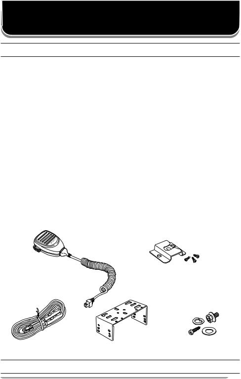
SUPPLIED ACCESSORIES
Item |
Part Number |
Quantity |
KMC-30 Microphone (K type only) |
T91-0624-XX |
1 |
|
|
|
Microphone hanger (K type only) |
J19-1584-XX |
1 |
|
|
|
DC power cable |
E30-3339-XX |
1 |
|
|
|
• Fuse (10 A) |
F51-0016-XX |
2 |
|
|
|
Mounting bracket |
J29-0662-XX |
1 |
|
|
|
Screw set: |
|
|
• Self-tapping screw (4 pieces) |
|
|
• Hex-headed screw with washer (4 pieces) |
N99-0395-XX |
1 |
• Spring washer (4 pieces) |
|
|
• Flat washer (4 pieces) |
|
|
|
|
|
Instruction manual |
B62-1778-XX |
1 |
|
|
|
KMC-30 Microphone |
Microphone hanger |
DC power cable with fuses |
Mounting bracket |
Screw set |
Note: The microphone and microphone hanger are not supplied with M or M2 type models. The model type is marked on the carton.
1
PREPARATION
Various electronic equipment in your vehicle may malfunction if they are not properly protected from the radio frequency energy which is present while transmitting. Electronic fuel injection, anti-skid braking, and cruise control systems are typical examples of equipment that may malfunction. If your vehicle contains such equipment, consult the dealer for the make of vehicle and enlist his/her aid in determining if they will perform normally while transmitting.
Note: The following preparation instructions are for use by your KENWOOD dealer, an authorized KENWOOD service facility, or the factory.
TOOLS REQUIRED
Note: Before installing the transceiver, always check how far the mounting screws will extend below the mounting surface. When drilling mounting holes, be careful not to damage vehicle wiring or parts.
The following tools are required for installing the transceiver:
•6 mm (1/4 inch) or larger electric drill
•4.2 mm (5/32 inch) drill bit for the self-tapping screws
•Circle cutters
POWER CABLE CONNECTION
The transceiver operates in 12 V negative ground systems only! Check the battery polarity and voltage of the vehicle before installing the transceiver.
1Check for an existing hole, conveniently located in the firewall, where the power cable can be passed through.
•If no hole exists, use a circle cutter to drill the firewall, then install a rubber grommet.
2Run the two power cable leads through the firewall and into the engine compartment, from the passenger compartment.
3Connect the red lead to the positive (+) battery terminal and the black lead to the negative (–) battery terminal.
•Locate the fuse as close to the battery as possible.
4Coil and secure the surplus cable with a retaining band.
•Be sure to leave enough slack in the cables so the transceiver can be removed for servicing while keeping the power applied.
2

INSTALLING THE TRANSCEIVER
For passenger safety, install the transceiver securely, using the supplied mounting bracket, so the transceiver will not break loose in the event of a collision.
1Mark the position of the holes in the dash by using the mounting bracket as a template. Drill the holes, then attach the mounting bracket using the supplied self-tapping screws.
•Be sure to mount the transceiver in a location where the controls are within easy reach of the user and where there is sufficient space at the rear of the transceiver for cable connections.
2Connect the antenna and the supplied power cable to the transceiver.
3Slide the transceiver into the mounting bracket and secure it using the supplied hex-headed screws.
4Mount the microphone hanger in a location where it will be within easy reach of the user.
•The microphone and microphone cable should be mounted in a place where they will not interfere with the safe operation of the vehicle.
When replacing the fuse in the DC power cable, be sure to replace it with a fuse of the same value.
Never replace a fuse with a fuse that has a higher value.
Flat washer |
Spring |
|
|
washer |
|
Hex-headed |
Self-tapping screw |
|
screws |
||
|
Antenna connector
Power input connector
Black cable
Red cable
DC power cable
Microphone
Mounting bracket
|
12 V |
|
vehicle |
Fuse |
battery |
Note: The microphone is supplied only with K type models. It is not supplied with M or M2 type models. The model type is marked on the carton.
3
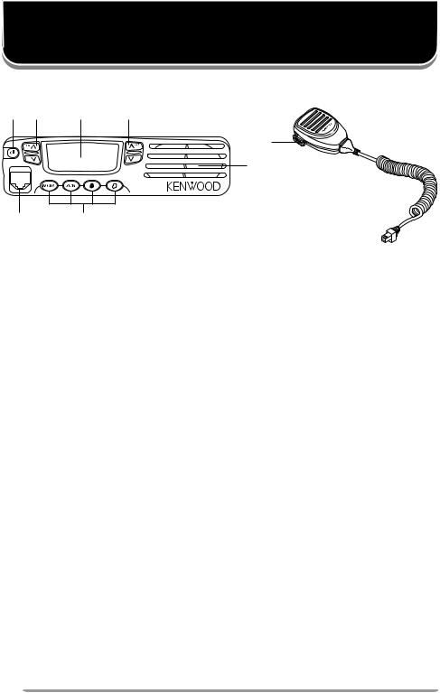
ORIENTATION
FRONT PANEL
q w e r
i
u
y t
q  (Power) switch
Press to switch the transceiver ON. Press and hold for approximately 1 second to switch the transceiver OFF.
wVOL  /
/  keys (left side)
Press to increase or decrease the volume level.
eDisplay
Refer to page 5.
rCH  /
/  keys (right side)
Press to increase or decrease the channel number.
tMON / SCN / ● / O keys
PF (Programmable Function) keys. Press each key to activate its programmable function (page 6).
yMicrophone jack
Insert the microphone plug into this jack.
uSpeaker
Internal speaker.
iPTT switch
Press this switch, then speak into the microphone to call a station.
4
 Loading...