


Kenwood TK-D840H, TK-D840, TK-D740HV, TK-D740H, TK-D740 User Manual
...TK-D740
TK-D740H TK-D740HV TK-D840 TK-D840H TK-D840HU
VHF DIGITAL TRANSCEIVER UHF DIGITAL TRANSCEIVER
USER MANUAL
B5A 0925-00/01

Contents |
|
PREPARATION...................................................................................................................... |
4 |
Connecting the power cable............................................................................................ |
4 |
Installing the Transceiver................................................................................................. |
4 |
ORIENTATION........................................................................................................................ |
6 |
FRONT AND REAR VIEWS................................................................................................ |
6 |
DISPLAY............................................................................................................................. |
8 |
PROGRAMMABLE FUNCTIONS........................................................................................ |
11 |
BASIC OPERATION............................................................................................................. |
15 |
SWITCHING POWER ON/ OFF....................................................................................... |
15 |
Transceiver Password.................................................................................................... |
15 |
ADJUSTING THE VOLUME.............................................................................................. |
15 |
SELECTING A ZONE AND CHANNEL............................................................................. |
15 |
TRANSMITTING............................................................................................................... |
15 |
RECEIVING...................................................................................................................... |
16 |
Receiving Group Calls................................................................................................... |
16 |
Receiving Individual Calls.............................................................................................. |
16 |
FleetSync: ALPHANUMERIC 2-WAY PAGING FUNCTION............................................... |
17 |
SELCALL (SELECTIVE CALLING)................................................................................... |
17 |
Transmitting................................................................................................................... |
17 |
Receiving....................................................................................................................... |
17 |
Identification Codes....................................................................................................... |
17 |
PAGING CALL............................................................................................................... |
17 |
SCAN.................................................................................................................................... |
18 |
PRIORITY SCAN.............................................................................................................. |
18 |
TEMPORARY CHANNEL LOCKOUT............................................................................... |
18 |
SCAN DELETE/ ADD........................................................................................................ |
18 |
DTMF CALLS....................................................................................................................... |
19 |
MANUAL DIALING............................................................................................................ |
19 |
AUTODIAL........................................................................................................................ |
19 |
REDIALING....................................................................................................................... |
19 |
2

ADVANCED OPERATIONS................................................................................................. |
20 |
EMERGENCY CALLS....................................................................................................... |
20 |
Lone Worker Mode........................................................................................................ |
20 |
SCRAMBLER.................................................................................................................... |
21 |
MONITOR/ SQUELCH OFF.............................................................................................. |
21 |
Squelch Level................................................................................................................ |
22 |
PUBLIC ADDRESS (PA)................................................................................................... |
22 |
HORN ALERT................................................................................................................... |
22 |
GPS REPORT................................................................................................................... |
22 |
DMR...................................................................................................................................... |
23 |
INDIVIDUAL/GROUP CALLS............................................................................................ |
23 |
Receiving....................................................................................................................... |
23 |
BACKGROUND OPERATIONS........................................................................................... |
24 |
TIME-OUT TIMER (TOT).................................................................................................. |
24 |
AUXILIARY PORT............................................................................................................. |
24 |
DISPLAY BRIGHTNESS................................................................................................... |
24 |
BUSY CHANNEL LOCKOUT (BCL).................................................................................. |
24 |
PTT ID............................................................................................................................... |
25 |
SIGNALING ...................................................................................................................... |
25 |
COMPANDER................................................................................................................... |
25 |
VOICE ANNUNCIATION................................................................................................... |
25 |
3
PREPARATION
WARNING
Various electronic equipment in your vehicle may malfunction if they are not properly protected from the radio frequency energy which is present while transmitting. Typical examples include electronic fuel injection, anti-skid braking, and cruise control. If your vehicle contains such equipment, consult the dealer for the make of vehicle and enlist his/her aid in determining if they will perform normally while transmitting.
Connecting the power cable
CAUTION
The transceiver operates in 12 V negative ground systems only! Check the battery polarity and voltage of the vehicle before installing the transceiver.
1Check for an existing hole, conveniently located in the firewall, where the power cable can be passed through.
•If no hole exists, use a circle cutter to drill a hole, then install a rubber grommet.
2Run the power cable through the firewall and into the engine compartment.
3Connect the red lead to the positive (+) battery terminal and the black lead to the negative (–) battery terminal.
•Place the fuse as close to the battery as possible.
4Coil the surplus cable and secure it with a retaining band.
•Be sure to leave enough slack in the cables so the transceiver can be removed for servicing while keeping the power applied.
Installing the Transceiver
WARNING
For passenger safety, install the transceiver securely using the supplied mounting bracket and screw set so the transceiver will not break loose in the event of a collision.
Note:
Before installing the transceiver, check how far the mounting screws will extend below the surface. When drilling mounting holes, be careful not to damage vehicle wiring or parts.
1Mark the position of the holes in the dash, using the mounting bracket as a template. Using a 4.2 mm (5/32 inch) drill bit, drill the holes, then attach the mounting bracket using the supplied screws.
•Mount the transceiver within easy reach of the user and where there is sufficient space at the rear of the transceiver for cable connections.
2Connect the antenna and the supplied power cable to the transceiver.
4
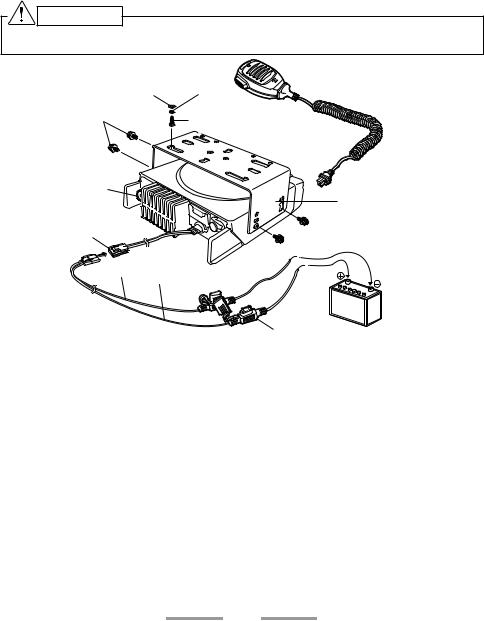
3Slide the transceiver into the mounting bracket and secure it using the supplied hex-headed screws.
4Mount the microphone hanger in a location where it will be within easy reach of the user.
•The microphone and microphone cable should be mounted in a place where they will not interfere with the safe operation of the vehicle.
CAUTION
When replacing the fuse in the DC power cable, be sure to replace it with a fuse of the same value. Never replace a fuse with one that is rated with a higher value.
Flat |
Spring |
Microphone |
|
washer |
washer |
||
|
|||
M4 x 8 mm |
5 x 16 mm Self-tapping |
||
Hex-headed screw |
|||
|
screw |
|
|
Antenna connector |
|
|
|
|
|
Mounting bracket |
|
Power input |
|
|
|
connector |
|
|
|
Black (–) cable |
|
||
|
Red (+) cable |
|
|
|
|
12 V vehicle |
|
DC power cable |
|
battery |
|
|
|
||
|
|
Fuse |
|
5

ORIENTATION
FRONT AND REAR VIEWS
ACC.

 (Power) switch
Press to switch the transceiver ON or OFF.

 /
/  keys
keys
Press to activate their programmable functions.
 Display
Refer to page 8.

 /
/  keys
keys
Press to activate their programmable functions.
 TX/RX Indicator
Lights red while transmitting. Lights green while receiving a signal. Flashes orange when receiving an optional signaling call.
 Microphone jack
Insert the microphone plug into this jack.
 Status Indicator
Lights during a specified mode, based on dealer programming.
 S / A / <B / C> /
  keys
keys
Press to activate their programmable functions.
 Speaker
Internal speaker.
 PTT switch
Press this switch, then speak into the microphone to call a station.
6

 Antenna connector
Connect the antenna to this connector.
 ACC connector
Connect the ACC to this connector, via the KCT-60.
 External speaker jack
Connect an external speaker to this jack.
 Power input connector
Connect the DC Power Cable to this connector.
7

DISPLAY
The display shows the zone/ channel number and the left and right dots show various modes of operation.
Display |
Description |
Zone Display (Zone 1)
Channel Display (Channel 16)
Appears during Scan. (Sc)
Appears during the transceiver is stunned. (St)
Appears when switch the transceiver ON.
The Transceiver Password function is programmed. (PS)
Appears when the Squelch Level setting is activated. (SL)
Appears when the Talk Around function is activated. (tA)
Appears when the Horn Alert function is activated. (HA)
Appears when the Public Address function is activated. (PA)
Appears when the AUX function is activated. (AU)
Appears when a zone is added to the scan list. (GA)
Appears when a zone is removed from the scan list. (Gd)
Appears when a channel is added to the scan list. (cA)
Appears when a channel is removed from the scan list. (cd)
Appears when the Lone Worker function is activated. (Ln)
8
 Loading...