


TK-7360/ TK-8360
VHF FM TRANSCEIVER/ UHF FM TRANSCEIVER
INSTRUCTION MANUAL
ÉMETTEUR-RÉCEPTEUR FM VHF/ ÉMETTEUR-RÉCEPTEUR FM UHF
MODE D’EMPLOI
TRANSCEPTOR FM VHF/ TRANSCEPTOR FM UHF
MANUAL DE INSTRUCCIONES
RICETRASMETTITORE FM VHF/ RICETRASMETTITORE FM UHF
MANUALE DI ISTRUZIONI
VHF-FM-TRANSCEIVER/ UHF-FM-TRANSCEIVER
BEDIENUNGSANLEITUNG
VHF FM ZENDONTVANGER/ UHF FM ZENDONTVANGER
GEBRUIKSAANWIJZING
VHF FM EL TELSİZİ/ UHF FM EL TELSİZİ
KULLANIM KILAVUZU
ΠΟΜΠΟΔΕΚΤΗΣ VHF FM/ ΠΟΜΠΟΔΕΚΤΗΣ UHF FM
ΟΔΗΓΙΕΣ ΧΡΗΣΗΣ
© B62 2282 00 (E)
09 08 07 06 05 04 03 02 01 00

VHF FM TRANSCEIVER/ UHF FM TRANSCEIVER
TK-7360/ TK-8360
INSTRUCTION MANUAL
ENGLISH
Firmware Copyrights
The title to and ownership of copyrights for firmware embedded in Kenwood product memories are reserved for Kenwood Corporation.
NOTIFICATION
This equipment complies with the essential requirements of Directive 1999/5/EC.
The use of the warning symbol means the equipment is subject to restrictions of use in certain countries.
This equipment requires a licence and is intended for use in the countries as below.
AT |
BE |
DK |
FI |
FR |
DE |
GR |
IS |
IE |
IT |
LI |
LU |
NL |
NO |
PT |
ES |
SE |
CH |
GB |
CY |
CZ |
EE |
HU |
LV |
LT |
MT |
PL |
SK |
SI |
BG |
RO |
|
ISO3166

Information on Disposal of Old Electrical and Electronic Equipment and Batteries (applicable for EU countries that have adopted separate waste collection systems)
Products and batteries with the symbol (crossed-out wheeled bin) cannot be disposed as
household waste.
Old electrical and electronic equipment and batteries should be recycled at a facility capable of handling these items and their waste byproducts.
 Contact your local authority for details in locating a recycle facility nearest to you. Proper recycling and waste disposal will help conserve resources whilst preventing
detrimental effects on our health and the environment.
Notice: The sign "Pb" below the symbol for batteries indicates that this battery contains lead.

Thank You
We are grateful you have chosen Kenwood for your personal mobile applications.
This instruction manual covers only the basic operations of your mobile radio. Ask your dealer for information on any customized features they may have added to your radio.
Notices to the User
Government law prohibits the operation of unlicensed transmitters within the territories under government control.
Illegal operation is punishable by fine and/or imprisonment.
Refer service to qualified technicians only.
SAFETY: It is important that the operator is aware of, and understands, hazards common to the operation of any transceiver.
EXPLOSIVE ATMOSPHERES (GASES, DUST, FUMES, etc.)
Turn OFF your transceiver while taking on fuel or while parked in gasoline service stations. Do not carry spare fuel containers in the trunk of your vehicle if your transceiver is mounted in the trunk area.
INJURY FROM RADIO FREQUENCY TRANSMISSIONS
Do not operate your transceiver when somebody is either standing near to or touching the antenna, to avoid the possibility of radio frequency burns or related physical injury.
DYNAMITE BLASTING CAPS
Operating the transceiver within 500 feet (150 m) of dynamite blasting caps may cause them to explode. Turn OFF your transceiver when in an area where blasting is in progress, or where “TURN OFF TWO-WAY RADIO” signs have been posted. If you are transporting blasting caps in your vehicle, make sure they are carried in a closed metal box with a padded interior. Do not transmit while the caps are being placed into or removed from the container.

Precautions
Observe the following precautions to prevent fire, personal injury, and transceiver damage.
•Do not attempt to configure the transceiver while driving; it is too dangerous.
•Do not disassemble or modify the transceiver for any reason.
•Do not expose the transceiver to long periods of direct sunlight, nor place it near heating appliances.
•If an abnormal odor or smoke is detected coming from the transceiver, switch the transceiver power off immediately, and contact your Kenwood dealer.
•Use of the transceiver while you are driving may be against traffic laws. Please check and observe the vehicle regulations in your area.
•Do not use options not specified by Kenwood.
The transceiver operates in 12 V negative ground systems only! Check the battery polarity and voltage of the vehicle before installing the transceiver.
Use only the supplied DC power cable or a Kenwood optional DC power cable.
Do not cut and/or remove the fuse holder on the DC power cable.
For passenger safety, install the transceiver securely using the supplied mounting bracket and screw set so the transceiver will not break loose in the event of a collision.
CONTENTS |
|
Getting Started................................................................................................. |
1 |
GETTING ACQUAINTED.......................................................................................... |
3 |
Programmable FUnctions.............................................................................. |
5 |
BASIC OPERATIONS............................................................................................... |
6 |
Scan........................................................................................................................ |
7 |
DTMF CALLS............................................................................................................ |
8 |
Signaling............................................................................................................. |
10 |
5-Tone Signaling............................................................................................... |
10 |
FleetSync: alphanumeric 2-way paging Function.................................... |
11 |
Advanced Operations.................................................................................... |
13 |
Background Operations.............................................................................. |
16 |
VGS-1 OPTIONAL VOICE GUIDE & STORAGE UNIT........................................... |
17 |
ii
GETTING STARTED
Note: The following instructions are for use by your Kenwood dealer, an authorized Kenwood service facility, or the factory.
Supplied Accessories
Carefully unpack the transceiver. We recommend that you identify the items listed below before discarding the packing material. If any items are missing or have been damaged during shipment, file a claim with the carrier immediately.
DC power cable (with fuses) . . . . . . . |
. . . . |
. |
. |
. . . . |
1 |
||
• |
10 A fuse . . . . . . . . . . . . . |
. . . . |
|
2 |
|||
Mounting Bracket . . . . . . . . . . . |
. . . . . |
. |
|
1 |
|||
Screw set |
|
|
|
|
|
|
|
• |
5 x 16 mm self-tapping screw . . . . . |
. . . . |
. |
. |
. . . . |
. . |
4 |
• |
Hex-headed screw with washer . . . . |
. . . . |
. |
. |
. . . . |
. . |
. 4 |
• |
Spring washer . . . . . . . . . . . |
. . . . |
. |
. |
4 |
||
• |
Flat washer . . . . . . . . . . . . |
. . . . |
. |
4 |
|||
Instruction manual . . . . . . . . . . . |
. . . . |
. |
. |
1 |
|||
Preparation
Various electronic equipment in your vehicle may malfunction if they are not properly protected from the radio frequency energy which is present while transmitting. Typical examples include electronic fuel injection, anti-skid braking, and cruise control. If your vehicle contains such equipment, consult the dealer for the make of vehicle and enlist his/her aid in determining if they will perform normally while transmitting.
ν Power Cable Connection
The transceiver operates in 12 V negative ground systems only! Check the battery polarity and voltage of the vehicle before installing the transceiver.
1Check for an existing hole, conveniently located in the firewall, where the power cable can be passed through.
•If no hole exists, use a circle cutter to drill a hole, then install a rubber grommet.
2Run the power cable through the firewall and into the engine compartment.
3Connect the red lead to the positive (+) battery terminal and the black lead to the negative (–) battery terminal.
•Place the fuse as close to the battery as possible.
4Coil the surplus cable and secure it with a retaining band.
•Be sure to leave enough slack in the cables so the transceiver can be removed for servicing while keeping the power applied.

ν Installing the Transceiver
For passenger safety, install the transceiver securely using the supplied mounting bracket and screw set, so the transceiver will not break loose in the event of a collision.
Note: Before installing the transceiver, check how far the mounting screws will extend below the surface. When drilling mounting holes, be careful not to damage vehicle wiring or parts.
1Mark the position of the holes in the dash, using the mounting bracket as a template. Using a 4.2 mm (5/32 inch) drill bit, drill the holes, then attach the mounting bracket using the supplied screws.
•Mount the transceiver within easy reach of the user and where there is sufficient space at the rear of the transceiver for cable connections.
2Connect the antenna and the supplied power cable to the transceiver.
3Slide the transceiver into the mounting bracket and secure it using the supplied hex-headed screws.
4Mount the optional microphone hanger in a location where it will be within easy reach of the user.
•The microphone and microphone cable should be mounted in a place where they will not interfere with the safe operation of the vehicle.
When replacing the fuse in the DC power cable, be sure to replace it with a fuse of the same value. Never replace a fuse with one that is rated with a higher value.
|
Flat |
Spring |
Optional |
|
M4 x 6 mm |
washer |
washer |
Microphone |
|
|
5 x 16 mm |
|
|
|
Hex-headed screw |
|
|
||
|
|
Self-tapping screw |
|
|
Antenna |
|
|
|
|
connector |
|
|
Mounting bracket |
|
|
|
|
||
Power input |
|
|
|
|
connector |
|
|
|
|
Black (–) cable |
|
|
|
|
|
Red (+) cable |
|
|
|
|
|
|
12 |
V vehicle |
DC power cable |
Fuse |
|
battery |
|
|
|
|||
|
|
|
|
|
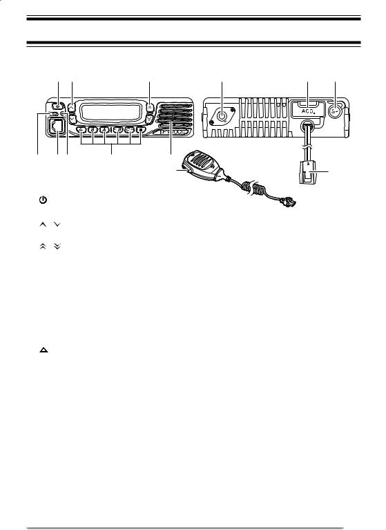
GETTING ACQUAINTED
Front and Rear Views
: @ |
. |
|
|
; =B |
> |
2 |
|
|
|
8 |
|
(Power) switch
Press to switch the transceiver ON or OFF.
/ keys
Press to activate their programmable functions {page 5}.
/ keys
Press to activate their programmable functions {page 5}.
TX/RX Indicator
Lights red while transmitting and green while receiving a signal. Flashes orange when receiving an optional signaling call.
Microphone jack
Insert the microphone plug into this jack.
Status Indicator
Lights blue during a specified mode, based on dealer programming.
/ S / A / <B / C> / ■ keys
Press to activate their programmable functions {page 5}.
Speaker
Internal speaker.
PTT switch
Press this switch, then speak into the microphone to call a station.
Antenna connector
Connect the antenna to this connector.
ACC connector
Connect the ACC to this connector, via the KCT-60.
External speaker jack
Connect an external speaker to this jack.
Power input connector
Connect the DC Power Cable to this connector.
 Loading...