


INSTRUCTION MANUAL
144/440 MHz FM DUAL BANDER
TH-G71A
144/430 MHz FM DUAL BANDER
TH-G71A
144/430 MHz FM DUAL BANDER
TH-G71E
KENWOOD CORPORATION
© B62-0739-20 (K,E,T,M) 09 08 07 06 05 04 03 02

|
THANK YOU! |
1 |
We are grateful you decided to purchase this |
KENWOOD FM transceiver. This series of handhelds |
|
2 |
was developed to satisfy the requirement for a compact |
rig that’s simple to operate yet contains numerous |
|
3 |
sophisticated features. KENWOOD believes that the |
compact size, coupled with reasonable cost, will meet |
|
|
your satisfaction. |
4 |
|
5 MODELS COVERED BY THIS MANUAL
The models listed below are covered by this manual.
6 TH-G71A: 144/440 MHz FM Dual Bander (U.S.A./ Canada)
7 TH-G71A: 144/430 MHz FM Dual Bander
8 |
(General market) |
|
TH-G71E: 144/430 MHz FM Dual Bander |
||
|
||
9 |
(Europe) |
|
|
10
11
12
13
14
15
FEATURES
This transceiver has the following main features.
•Contains a total of 200 memory channels programmable with separate receive and transmit frequencies as well as simplex frequencies, and other various data.
•Allows each memory channel to be named using up to 6 alphanumeric characters; you may assign a name such as a callsign or repeater name.
•If programmed, the built-in Continuous Tone Coded Squelch System (CTCSS) rejects unwanted calls from other persons who are using the same frequency.
•Equipped with a high performance antenna.
•Illuminates the keys on the keypad as well as the display to permit easy operation in the dark.
2

NOTICES TO THE USER
ATTENTION (U.S.A. Only):
The RBRC Recycle seal found on KENWOOD nickel-cadmium (Ni-Cd) battery packs indicates KENWOOD’s voluntary participation in an industry program to collect and recycle Ni-Cd batteries after
their operating life has expired. The RBRC program is an alternative to disposing Ni-Cd batteries with
your regular refuse or in municipal waste streams, which is illegal in some areas.
For information on Ni-Cd battery recycling in your area, call (toll free)
1-800-8-BATTERY (1-800-822-8837).
KENWOOD’s involvement in this program is part of our commitment to preserve our environment and conserve our natural resources.
One or more of the following statements may be applicable:
FCC WARNING
This equipment generates or uses radio frequency energy. Changes or modifications to this equipment may cause harmful interference unless the modifications are expressly approved in the instruction manual. The user could lose the authority to operate this equipment if an unauthorized change or modification is made.
INFORMATION TO THE DIGITAL DEVICE USER REQUIRED BY THE FCC
This equipment has been tested and found to comply with the limits for a Class B digital device, pursuant to Part 15 of the FCC Rules.
These limits are designed to provide reasonable protection against harmful interference in a residential installation.
This equipment generates, uses and can generate radio frequency energy and, if not installed and used in accordance with the instructions, may cause harmful interference to radio communications.
However, there is no guarantee that the interference will not occur in a particular installation. If this equipment does cause harmful interference to radio or television reception, which can be determined by turning the equipment off and on, the user is encouraged to try to correct the interference by one or more of the following measures:
•Reorient or relocate the receiving antenna.
•Increase the separation between the equipment and receiver.
•Connect the equipment to an outlet on a circuit different from that to which the receiver is connected.
•Consult the dealer for technical assistance.
PRECAUTIONS
Please observe the following precautions to prevent fire, personal injury, or transceiver damage:
•Do not transmit with high output power for extended periods. The transceiver may overheat.
•Do not modify this transceiver unless instructed by this manual or by KENWOOD documentation.
•When using a regulated power supply, connect the specified DC cable (option) to the DC jack on the transceiver. The supply voltage must be between 6 V and 16 V to prevent damaging the transceiver.
•When connecting the transceiver to a cigarette lighter socket in a vehicle, use the specified cigarette lighter cable (option).
•Do not expose the transceiver to long periods of direct sunlight nor place the transceiver close to heating appliances.
•Do not place the transceiver in excessively dusty areas, humid areas, wet areas, nor on unstable surfaces.
•If an abnormal odor or smoke is detected coming from the transceiver, turn OFF the power immediately and remove the battery case or the battery pack from the transceiver. Contact a KENWOOD service station or your dealer.
i
1
2
3
4
5
6
7
8
9
10
11
12
13
14
15

CONTENTS
1 |
.....................................SUPPLIED ACCESSORIES |
1 |
|||
CONVENTIONS FOLLOWED IN THIS MANUAL |
1 |
||||
|
|||||
2 |
CHAPTER |
q |
PREPARATION |
|
|
|
|
||||
3 |
BATTERY OPERATING TIME .................................. |
2 |
|||
|
|
|
|
||
4 |
INSTALLING THE NiCd BATTERY PACK ................ |
2 |
|||
INSTALLING ALKALINE BATTERIES |
3 |
||||
|
|||||
5 |
INSTALLING THE ANTENNA ................................... |
4 |
|||
6 |
ATTACHING THE HAND STRAP ............................. |
4 |
|||
INSTALLING THE BELT HOOK |
4 |
||||
|
|||||
7 |
CHAPTER |
w |
FIRST QSO |
|
|
8 |
CHAPTER |
e |
GETTING ACQUAINTED |
|
|
ORIENTATION |
6 |
||||
|
|||||
9 |
BASIC TRANSCEIVER MODES .............................. |
6 |
|||
10 |
DISPLAY |
................................................................... |
|
7 |
|
CHAPTER |
r |
OPERATING BASICS |
|
||
|
|
||||
11 |
SWITCHING POWER ON/OFF ................................ |
8 |
|||
12 |
ADJUSTING VOLUME ............................................. |
8 |
|||
ADJUSTING SQUELCH |
8 |
||||
|
|||||
13 |
SELECTING A BAND ............................................... |
9 |
|||
14 |
SELECTING FREQUENCIES .................................. |
9 |
|||
|
|
|
|
||
|
TRANSMITTING ....................................................... |
9 |
|||
15 |
Selecting Output Power ....................................... |
9 |
|||
|
ii |
|
|
|
|
|
|
|
|
||
CHAPTER |
t |
MENU SET-UP |
|
WHAT IS A MENU? ................................................ |
10 |
||
MENU ACCESS ...................................................... |
10 |
||
MENU CONFIGURATION ...................................... |
11 |
||
CHAPTER |
y |
OPERATING THROUGH REPEATERS |
|
REPEATER ACCESS ............................................. |
12 |
||
Selecting Offset Direction .................................. |
13 |
||
Selecting Offset Frequency ............................... |
13 |
||
Activating Tone Function ................................... |
14 |
||
Selecting a Tone Frequency .............................. |
14 |
||
Automatic Repeater Offset |
|
||
(U.S.A./ Canada/ Europe Only) ......................... |
15 |
||
REVERSE FUNCTION ........................................... |
16 |
||
CHAPTER |
u |
MEMORY CHANNELS |
|
SIMPLEX&REPEATER OR ODD-SPLIT |
|
||
MEMORY CHANNEL? ........................................... |
17 |
||
STORING SIMPLEX FREQUENCIES OR |
|
||
STANDARD REPEATER FREQUENCIES ............. |
18 |
||
STORING ODD-SPLIT REPEATER |
|
||
FREQUENCIES ...................................................... |
18 |
||
RECALLING MEMORY CHANNELS ..................... |
19 |
||
CLEARING MEMORY CHANNELS........................ |
19 |
||
NAMING MEMORY CHANNELS............................ |
20 |
||
SWITCHING MEMORY NAME/ FREQUENCY |
|
||
DISPLAY |
................................................................. |
|
20 |
CALL CHANNEL ..................................................... |
21 |
Recalling the Call Channel ................................ |
21 |
Changing Call Channel Contents ...................... |
21 |
MEMORY VFO TRANSFERS ............................ |
22 |
CHANNEL DISPLAY FUNCTION ........................... |
22 |
INITIALIZING MEMORY ......................................... |
23 |
Partial Reset (VFO) ........................................... |
23 |
Full Reset (Memory) .......................................... |
23 |
CHAPTER i SCAN |
|
SCAN RESUME METHODS .................................. |
25 |
Selecting Scan Resume Method ....................... |
25 |
VFO SCAN.............................................................. |
26 |
MEMORY SCAN ..................................................... |
26 |
Locking Out Memory Channels ......................... |
27 |
MHz SCAN.............................................................. |
27 |
PROGRAM SCAN .................................................. |
28 |
Setting Scan Limits ............................................ |
28 |
Using Program Scan ......................................... |
29 |
CALL/VFO SCAN ................................................... |
29 |
CALL/MEMORY SCAN ........................................... |
29 |
PRIORITY SCAN .................................................... |
30 |
Storing Frequency in Priority Channel .............. |
30 |
Selecting Priority Scan Method ......................... |
31 |
Using Priority Scan ............................................ |
31 |
CHAPTER |
o |
CONTINUOUS TONE CODED |
|
|
|
SQUELCH SYSTEM (CTCSS) |
|
USING CTCSS ....................................................... |
32 |
||
Automatic Tone Frequency ID ........................... |
33 |
||
CHAPTER |
!0 |
DUAL TONE MULTI-FREQUENCY |
|
|
|
(DTMF) FUNCTIONS |
|
MAKING DTMF CALLS .......................................... |
34 |
||
DTMF Tone TX Hold .......................................... |
34 |
||
Autopatch (U.S.A. and Canada) ........................ |
34 |
||
STORING DTMF NUMBERS FOR AUTOMATIC |
|
||
DIALER |
................................................................... |
|
35 |
CONFIRMING ..........STORED DTMF NUMBERS |
35 |
||
TRANSMITTING .......STORED DTMF NUMBERS |
36 |
||
CHAPTER |
!1 |
AUXILIARY FUNCTIONS |
|
TX INHIBIT ............................................................. |
|
37 |
|
TRANSCEIVER ...........................................LOCK |
37 |
||
AUTOMATIC .........................POWER OFF (APO) |
37 |
||
BATTERY ...................................................SAVER |
37 |
||
LAMP FUNCTION .................................................. |
38 |
||
BEEP ON/OFF ........................................................ |
38 |
||
SWITCHING AM/FM MODE |
|
||
(U.S.A./ .......................................CANADA ONLY) |
38 |
||
TONE ALERT .......................................................... |
|
38 |
|
1
2
3
4
5
6
7
8
9
10
11
12
13
14
15
iii

1 |
PROGRAMMABLE VFO......................................... |
39 |
|||
CHANGING SPEAKER CONFIGURATIONS |
39 |
||||
|
|||||
2 |
KEYPAD DIRECT ENTRY |
40 |
|||
|
|||||
3 |
Frequency Entry ................................................ |
40 |
|||
Memory Channel Number Entry |
40 |
||||
|
|||||
4 |
CHANGING FREQUENCY STEP SIZE ................. |
40 |
|||
5 |
CHAPTER |
!2 |
MICROPHONE CONTROL |
|
|
CHAPTER |
!3 |
MAINTENANCE |
|
||
|
|
||||
6 |
GENERAL INFORMATION ..................................... |
42 |
|||
7 |
SERVICE ................................................................ |
|
42 |
||
SERVICE NOTE |
42 |
||||
|
|||||
8 |
CLEANING.............................................................. |
|
42 |
||
9 |
CHARGING THE NiCd BATTERY PACK ............... |
43 |
|||
TROUBLESHOOTING |
44 |
||||
|
|||||
10 |
CHAPTER |
!4 |
OPTIONAL ACCESSORIES |
|
|
11 |
CHAPTER |
!5 |
EQUIPMENT INSTALLATION AND |
|
|
|
|
CONNECTION |
|
||
12 |
CONNECTING AN EXTERNAL POWER |
|
|||
SOURCE |
|
47 |
|||
|
|
||||
13 |
Using a Regulated Power Supply...................... |
47 |
|||
Using a Cigarette Lighter Socket |
47 |
||||
|
|||||
14 |
CONNECTING EQUIPMENT FOR REMOTE |
|
|||
|
CONTROL .............................................................. |
|
48 |
||
15 |
|
|
|
|
|
CONNECTING OTHER EXTERNAL |
|
EQUIPMENT........................................................... |
48 |
SPECIFICATIONS
QUICK REFERENCE GUIDE
INDEX
iv

SUPPLIED ACCESSORIES
Accessory |
Part Number |
Quantity |
|
Antenna |
T90-0634-XX |
1 |
|
NiCd battery pack |
|
|
|
PB-38 (6 V, 650 mAh)1 |
W09-0909-XX |
1 |
|
PB-39 (9.6 V, 600 mAh)1 |
W09-0911-XX |
1 |
|
Battery case (BT-11)1 |
A02-2078-XX |
1 |
|
Battery charger |
|
1 |
|
U.S.A./ Canada |
W08-0437-XX |
||
United Kingdom |
W08-0438-XX |
1 |
|
Europe |
W08-0440-XX |
1 |
|
General |
W08-0441-XX |
1 |
|
|
|
|
|
AC plug adapter2 |
E19-0254-XX |
1 |
|
Belt hook |
J29-0631-XX |
1 |
|
|
|
|
|
Hand strap |
J69-0339-XX |
1 |
|
|
|
|
|
Warranty card |
— |
1 |
|
U.S.A./ Canada/ Europe only |
|||
|
|
||
|
|
|
|
Instruction manual |
B62-0739-XX |
1 |
|
|
|
|
1Depending on the markets, PB-38, PB-39, or BT-11 is provided.
2Some General market versions only
CONVENTIONS FOLLOWED IN THIS MANUAL
The writing conventions described below have been followed to simplify instructions and avoid unnecessary repetition.
ATTENTION: MOST PROCEDURES REQUIRE THAT YOU PRESS AN
APPROPRIATE KEY IN EACH STEP WITHIN APPROXIMATELY 10 SECONDS, OR THE PREVIOUS MODE WILL BE RESTORED.
Instruction |
What to do |
Press [KEY]. |
Press and release KEY. |
|
|
Press |
Press and hold KEY until |
[KEY] (1 s). |
the function begins. |
|
|
Press |
Press KEY1 momentarily, |
[KEY1], [KEY2]. |
release KEY1, then press |
|
KEY2. |
Press |
Press and hold KEY1, then |
[KEY1]+[KEY2]. |
press KEY2. |
|
|
Press |
With transceiver power OFF, |
[KEY]+ POWER ON. |
press and hold KEY, then |
|
press the PWR switch. |
|
|
1
2
3
4
5
6
7
8
9
10
11
12
13
14
15
1
PREPARATION
1 |
BATTERY OPERATING TIME |
|
|
|
|
|
|
|||||
2 |
The following table shows the approximate battery life |
|||||||||||
|
(hours) relative to the transmit output power. |
|
||||||||||
3 |
|
|
|
|
|
|
|
|
|
|
|
|
|
Batteries |
|
VHF Band |
|
|
UHF Band |
|
|||||
|
|
|
|
|
|
|||||||
4 |
|
HI |
|
LO |
|
EL |
HI |
|
LO |
|
EL |
|
|
|
|
|
|
|
|||||||
5 |
|
PB-38 NiCd |
4.5 |
|
10 |
|
13 |
4.5 |
|
8 |
|
12 |
|
|
|
|
|
|
|
|
|
|
|
|
|
|
PB-39 NiCd |
3.5 |
|
8 |
|
14 |
3.2 |
|
7.2 |
|
14 |
|
|
|
|
|
|
|
|||||||
6 |
|
|
|
|
|
|
|
|
|
|
|
|
|
Alkaline |
14 |
|
28 |
|
40 |
14 |
|
27 |
|
30 |
|
|
|
|
|
|
|
|||||||
7 |
|
|
|
|
|
|
|
|
|
|
|
|
|
|
|
|
|
|
|
|
|
|
|
|
|
INSTALLING THE NiCd BATTERY PACK
8
Note: Because the battery pack is provided uncharged, charge the 9 battery pack before using it with the transceiver. For the method of
charging the battery pack, refer to “CHARGING THE NiCd BATTERY PACK” {page 43}.
10
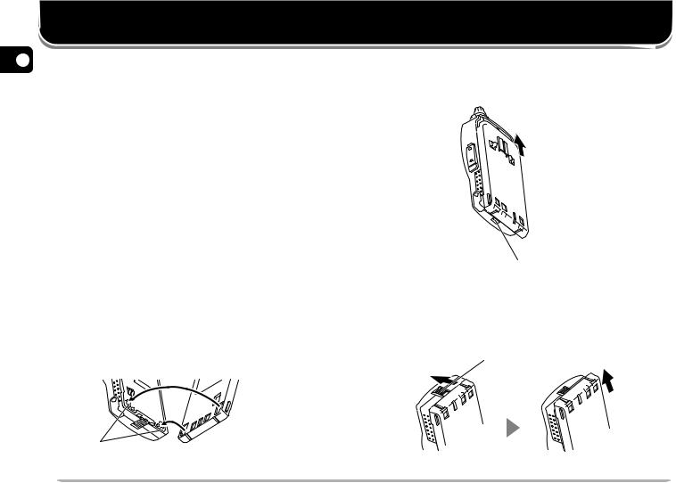
1 Position the two grooves on the inside bottom corners
11of the battery pack over the corresponding guides on the back of the transceiver.
12
13
14
Guide
15
2Slide the battery pack along the back of the transceiver until the release latch on the base of the transceiver locks the battery pack in place.
Release latch
3To remove the battery pack, push up the release latch, then slide the battery pack back.
Release latch
2
INSTALLING ALKALINE BATTERIES
WARNING!
DO NOT INSTALL THE BATTERIES IN A HAZARDOUS ENVIRONMENT WHERE SPARKS COULD CAUSE AN
EXPLOSION.
NEVER DISCARD OLD BATTERIES IN FIRE BECAUSE EXTREMELY HIGH TEMPERATURES CAN CAUSE BATTERIES
TO EXPLODE.
Note:
It is recommended to use high quality alkaline batteries rather than manganese batteries to enjoy longer periods of battery life. Do not use commercially available NiCd batteries.
If you will not use the transceiver for a long period, remove the batteries from the battery case.
Do not use different quality of batteries together.
When the battery voltage is low, replace all four old batteries with new ones.
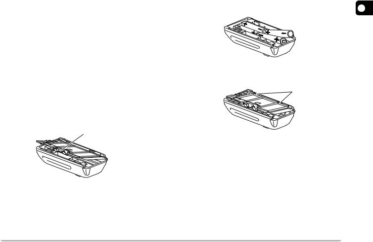
1To open the battery case cover, push on the locking tab, then pull the cover.
Locking tab
2 Insert (or remove) four AA (LR6) alkaline batteries.
• Be sure to match the battery polarities with those |
|
marked on the bottom of the battery case. |
1 |
|
2 |
3
4
3 Align the two tabs on the battery case cover, then |
5 |
|
close the cover until the locking tab clicks. |
||
|
Tab |
6 |
|
|
|
7 |
8
4 To install the battery case onto (or remove from) the |
9 |
|
|
||
transceiver, follow steps 1 to 3 for INSTALLING THE |
10 |
|
NiCd BATTERY PACK {page 2}. |
||
|
||
|
11 |
|
|
12 |
|
|
13 |
|
|
14 |
|
|
15 |
3
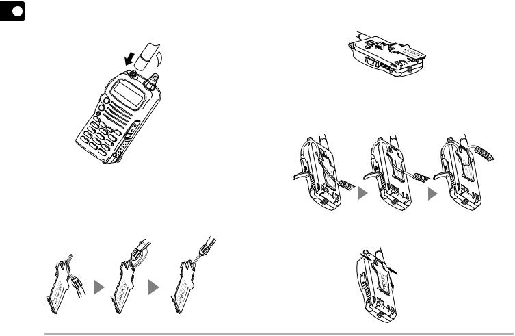
INSTALLING THE ANTENNA
Hold the provided antenna at its base, and screw the
1antenna into the connector on the top panel of the
2transceiver until it is snug.
3 |
q |
|
 w
w
4 5 6
7 8
9 ATTACHING THE HAND STRAP
10If you want, attach the provided hand strap to the belt hook before installing the hook onto the transceiver.
11
12
13
14
15
INSTALLING THE BELT HOOK
Install the provided belt hook onto the back of the battery pack or the battery case.
•To lock the cable of an optional speaker microphone, first position the cable over the left groove on the transceiver. Then install the belt hook. Last position the cable over the right groove.
To remove the belt hook, pull the belt hook downward while pushing its tabs from both sides.
4
FIRST QSO
The 7 steps given here will get you on the air in your first QSO right away. So, you can enjoy the exhilaration that comes with opening a brand new transceiver.
qPress the PWR switch for 1 second or longer.
wTurn the VOL control clockwise to the 11 o’clock position.
ePress [BAND] to select the VHF or UHF band.
rTurn the Tuning control to select a frequency.
tPress and hold the PTT switch, then speak in a normal tone of voice.
y Release the PTT switch to receive.
uRepeat steps t and y to continue communication.
Note: When received signals are too weak to recognize, press and hold [MONI] to hear clearer signals. You will, however, also hear background noise.
CAUTION:
THE RECOMMENDED DUTY CYCLE IS
1 MINUTE OF TRANSMISSION AND
3 MINUTES OF RECEPTION. LONGER TRANSMISSIONS OR EXTENDED
OPERATION IN THE HIGH POWER MODE
MAY CAUSE THE BACK OF THE TRANSCEIVER TO GET HOT.
TRANSMITTING WITH THE SUPPLIED
ANTENNA NEAR OTHER ELECTRONIC
|
EQUIPMENT CAN INTERFERE WITH THAT |
|
r |
EQUIPMENT. ALSO, TRANSMITTING NEAR |
|
A REGULATED POWER SUPPLY, THAT IS |
||
w |
NOT RECOMMENDED BY KENWOOD, MAY |
|
CAUSE THE POWER SUPPLY TO OUTPUT |
||
|
||
|
AN EXTREMELY HIGH VOLTAGE. THIS |
|
|
VOLTAGE COULD DAMAGE BOTH YOUR |
|
|
TRANSCEIVER AND ANY OTHER |
|
|
EQUIPMENT CONNECTED TO THE POWER |
|
|
SUPPLY. |
|
t |
Note: If input voltage exceeds approximately 18 V, |
|
|
||
y |
warning beeps sound and “DC ERR” appears on |
|
|
the display. |
e
q
1
2
3
4
5
6
7
8
9
10
11
12
13
14
15
5

GETTING ACQUAINTED
1 |
ORIENTATION |
|
|
2 |
|
|
|
3 |
|
|
|
4 |
|
|
|
5 |
|
|
|
|
|
Antenna |
|
6 |
|
Tuning control |
|
|
PTT |
||
7 |
VOL control |
||
switch |
|||
On Air/Busy |
|||
|
LAMP |
||
8 |
lamp |
||
key |
|||
Display |
|||
|
MONI |
||
9 |
|
||
key |
Speaker/ |
||
|
|
Microphone |
|
10 |
BAND |
SP jack |
|
|
key |
MIC jack |
|
11 |
LOW |
||
|
|||
key |
Keypad |
||
|
|||
12 |
PWR |
DC IN |
|
switch |
jack |
||
|
13
BASIC TRANSCEIVER MODES
This section introduces you to the basic modes you can select on this transceiver.
VFO mode
Press [VFO] to select. In this mode you can change the operating frequency using the Tuning control.
Memory Recall mode
Press [MR] to select. In this mode you can change memory channels, using the Tuning control, where you stored frequencies and related data. You cannot enter this mode unless you program one memory channel at least. For further information, refer to “MEMORY CHANNELS” {page 17}.
14
15
6
Menu mode
Press [F], [BAND] to select. In this mode you can change Menu Nos. using the Tuning control.
2
1
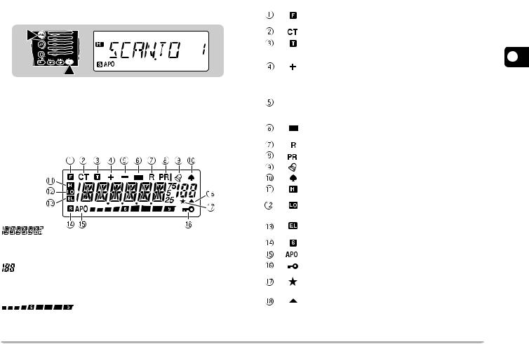
DISPLAY
On the display you will see various indicators that show what you have selected. Sometimes you may not recall what those indicators mean or how you can cancel the current setting. In such a case, you will find the following table very useful.
Displays various alphanumeric information such as an operating frequency or menu selection.
Displays the current memory channel when in Memory Recall mode.
Shows the strength of received signals. While transmitting, shows the current relative battery charge.
|
Indicator |
What You Selected |
What You Press |
Ref. |
|||
|
to Cancel |
Page |
|||||
|
|
|
|
|
|
||
|
|
|
|
|
Second function select |
[F] |
— |
|
|
|
|
|
mode |
|
|
|
|
|
|
|
CTCSS |
[F], [6] |
32 |
|
|
|
|
|
Tone function |
[F], [LOW] |
14 |
|
|
|
|
|
Plus offset direction |
[F], [REV], |
|
|
|
|
|
|
|
[F], [REV] |
13 |
|
|
|
|
|
|
(TH-G71E: one |
|
|
|
|
|
|
|
|
|
|
|
|
|
|
|
more [F], [REV]) |
|
|
|
|
|
|
|
|
|
|
|
|
|
|
Minus offset direction |
[F], [REV] |
|
|
|
|
|
|
|
(TH-G71E: one |
13 |
|
|
|
|
|
|
||
|
|
|
|
|
|
more [F], [REV]) |
|
|
|
|
|
|
|
|
|
|
|
|
|
|
Minus offset direction |
[F], [REV] |
13 |
|
|
|
|
|
(–7.6 MHz)1 |
||
|
|
|
|
|
|
|
|
|
|
|
|
|
Reverse function |
[REV] |
16 |
|
|
|
|
|
Priority Scan |
[F], [8] |
31 |
|
|
|
|
|
|||
|
|
|
|
|
|
|
|
|
|
|
|
|
Tone Alert |
[F], [7] |
38 |
|
|
|
|
|
AM mode |
Use Menu No.16 |
38 |
|
|
|
|
|
High transmit power |
Default setting |
9 |
|
|
|
|
|
Low transmit power |
[LOW], [LOW] |
9 |
|
|
|
|
|
|
to restore default |
|
|
|
|
|
|
|
|
|
|
|
|
|
|
Economic low transmit |
[LOW] to restore |
9 |
|
|
|
|
|
power |
default |
|
|
|
|
|
|
Battery Saver |
Use Menu No. 4 |
37 |
|
|
|
|
|
Automatic Power Off |
Use Menu No. 5 |
37 |
|
|
|
|
|
Transceiver Lock |
[F] (1 s) |
37 |
|
|
|
|
|
|
|
|
|
|
|
|
|
Memory Channel |
[F], [0] |
27 |
|
|
|
|
|
Lockout |
||
|
|
|
|
|
|
|
|
|
|
|
|
|
Memory channel |
— |
18 |
|
|
|
|
|
containing data |
||
|
|
|
|
|
|
|
|
1 TH-G71E only |
|
|
|||||
1
2
3
4
5
6
7
8
9
10
11
12
13
14
15
7
OPERATING BASICS
1 |
SWITCHING POWER ON/OFF |
2 |
1 Press the PWR switch (1 s) to switch ON the |
|
transceiver. |
3 |
• A beep sounds. |
|
|
4 |
|
5 |
1s |
|
6
72 To switch OFF the transceiver, press the PWR switch (1 s) again.
8
ADJUSTING VOLUME
9
Turn the VOL control clockwise to increase the audio 10 level and counterclockwise to decrease the audio level.
11
12
13
•If background noise is inaudible because of the Squelch
14 |
function, press and hold [MONI], then turn the VOL control. |
While pressing [MONI], you will hear background noise. |
|
15 |
|
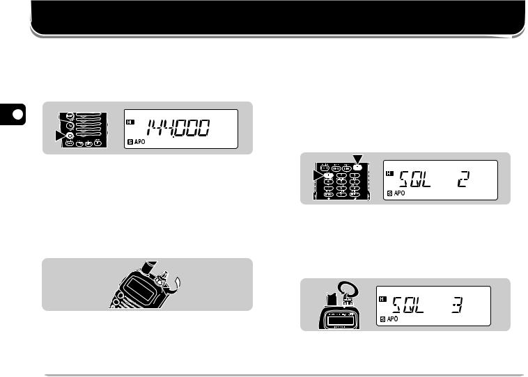
ADJUSTING SQUELCH
The purpose of the Squelch function is to silence background noise output from the speaker (squelch closed) when no signals are present. When the squelch level is set correctly, you will hear sound (squelch opened) only while a station is actually being received.
1Press [F], [1].
•The current squelch level appears. The default is level 2.
1
2
2Turn the Tuning control to select the squelch level in the range 0 to 5.
•Select just the level at which the background noise is eliminated when no signal is present.
•The larger the level number you select, the stronger the signals you need to receive to hear.
3Press any key other than [LAMP] and [MONI] to complete the setting.
8
SELECTING A BAND
Press [BAND] to select the VHF or UHF band.
Note: If in Memory Recall mode {page 6}, press [VFO], then press
[BAND] to select a band.
SELECTING FREQUENCIES
Turn the Tuning control clockwise to increase the frequency or counterclockwise to decrease the frequency.
•To change frequencies in steps of 1 MHz, press [MHz] first. 1 MHz digit blinks. Pressing [MHz] again cancels this function.
•If you cannot select a particular frequency, the frequency step size needs to be changed. See “CHANGING FREQUENCY STEP SIZE” {page 40}.
•You can also select frequencies with the numeric keys. See “KEYPAD DIRECT ENTRY” {page 40}.
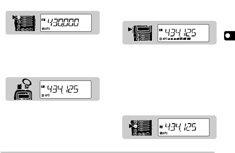
TRANSMITTING
1When ready to begin transmitting, press and hold the PTT switch and speak in a normal tone of voice.
•The On Air lamp lights red and the battery meter appears.
•Speaking too close to the microphone, or too loudly, may increase distortion and reduce intelligibility of your signal at the receiving station.
•The battery meter shows the current relative battery charge.
2When you finish speaking, release the PTT switch.
Time-Out Timer: Holding down the PTT switch for more than 10 minutes causes the transceiver to generate a beep and stop
transmitting. Release, then press the PTT switch to resume transmitting.
You cannot switch this function OFF.
nSelecting Output Power
Press [LOW] to select high (default), low, or economic low power (lowest).
• “HI”, “LO”, or “EL” appears to show the current selection.
Note: Selecting lower transmit power is a wise method to reduce battery consumption if communication is still reliable.
1
2
3
4
5
6
7
8
9
10
11
12
13
14
15
9
MENU SET-UP
1 |
WHAT IS A MENU? |
2 |
Many functions on this transceiver are selected or |
|
configured via a software-controlled Menu instead of |
3 |
physical controls on the transceiver. Once familiar with |
the Menu system, you will appreciate the versatility it |
offers.
4
5MENU ACCESS
61 Press [F], [BAND] to enter Menu mode.
•The last Menu No. used appears.
72
8
1
9
2 Turn the Tuning control to select the desired Menu 10 No.
3Press [BAND] to switch the selection.
•Depending on Menu Nos., press [BAND], then turn the Tuning control to select numeric values. Press [BAND] again to complete the setting.
4Press any key other than [BAND], [LAMP], and [MONI] to exit Menu mode.
11
12
13
14
15
10 

MENU CONFIGURATION
Menu |
Description |
Selections |
Default |
Ref. |
|
No. |
Page |
||||
|
|
|
|||
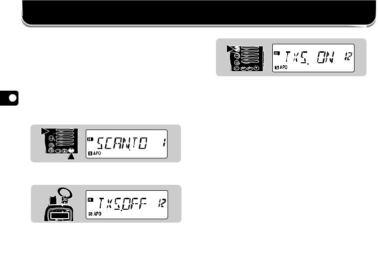
1 |
Scan resume method |
Time-Operated (TO)/ Carrier- |
Time-Operated |
25 |
|
Operated (CO)/ Seek (SE) |
|||||
|
|
|
|
||
|
|
|
|
|
|
2 |
Memory recall method |
All bands (ALL)/ |
All bands |
19 |
|
Single band (ONE) |
|||||
|
|
|
|
||
3 |
Programmable VFO |
Frequencies selectable on the |
Upper/lower receive |
39 |
|
(Upper/ lower limits) |
band |
frequency limits on the band |
|||
|
|
||||
|
|
|
|
|
|
4 |
Battery Saver |
ON/OFF |
ON |
37 |
|
|
|
|
|
|
|
5 |
Automatic Power Off |
ON/OFF |
ON |
37 |
|
|
|
|
|
|
|
6 |
Beep function |
ON/OFF |
ON |
38 |
|
|
|
|
|
|
|
7 |
Automatic Repeater Offset |
ON/OFF |
ON |
15 |
|
|
|
|
|
|
|
8 |
Offset frequency |
00.000 MHz to 29.950 MHz |
See reference page. |
13 |
|
|
|
|
|
|
|
9 |
Tuning Control Enable |
ON/OFF |
OFF |
37 |
|
|
|
|
|
|
|
10 |
DTMF number storing/ confirming |
See reference page. |
|
35 |
|
|
|
|
|
|
|
11 |
Priority Scan method |
Mode A/ Mode B |
Mode A |
31 |
|
|
|
|
|
|
|
12 |
TX Inhibit |
ON/OFF |
OFF |
37 |
|
|
|
|
|
|
|
13 |
DTMF Tone TX Hold |
ON/OFF |
OFF |
34 |
|
|
|
|
|
|
|
14 |
Speaker configuration |
Single speaker (ONE)/ |
Single speaker |
39 |
|
Two speakers (BOTH) |
|||||
|
|
|
|
||
|
|
|
|
|
|
15 |
Transceiver Control1 |
ON/OFF |
OFF |
— |
|
16 |
AM/FM selection2 |
AM mode/ FM mode |
AM mode |
38 |
|
(U.S.A./Canada only) |
|||||
|
|
|
|
||
|
|
|
|
|
1This menu item is used for controlling the transceiver using a personal computer. For further information, consult your dealer.
2This menu item is accessible only after selecting the 118 MHz band.
1
2
3
4
5
6
7
8
9
10
11
12
13
14
15
 11
11

OPERATING THROUGH REPEATERS
1Repeaters are often installed and maintained by radio clubs, sometimes with the cooperation of local
2businesses involved in the communications industry. Compared to simplex communication, you can usually
3transmit over much greater distances by using a
repeater. Repeaters are typically located on a mountain
4top or other elevated location. Often they operate at higher ERP (Effective Radiated Power) than a typical
5station. This combination of elevation and high ERP allows communications over considerable distances.
6
7
8
9
10
11
12TX: 144.725 MHz
TX tone: 88.5 Hz
13 RX: 145.325 MHz |
TX: 144.725 MHz |
|
TX tone: 88.5 Hz |
|
RX: 145.325 MHz |
14
15
REPEATER ACCESS
Most amateur radio voice repeaters use a separate receive and transmit frequency. You can set a separate transmit frequency by selecting the offset frequency and offset direction with respect to the receive frequency. In addition, some repeaters may require the transceiver to transmit a tone before the repeater can be used. To transmit this required tone, activate the Tone function and select a tone frequency.
The required offset direction, offset frequency, and tone frequency depend on the repeater you are accessing. Consult your local repeater reference.
Flow Chart for Repeater Access
Select a band.
Select a receive frequency.
Select an offset direction.
Select an offset frequency.
Activate the Tone function, if necessary.
Select a tone frequency, if necessary.
Press the PTT switch.
12 
 Loading...