


TK-762-H
VHF
FM
TRANSCEIVER
TK-760/762/H
SERVICE MANUAL
KENWOOD
© 1996-5 PRINTED
B51-8327-00 (N) 1382
IN
JAPAN
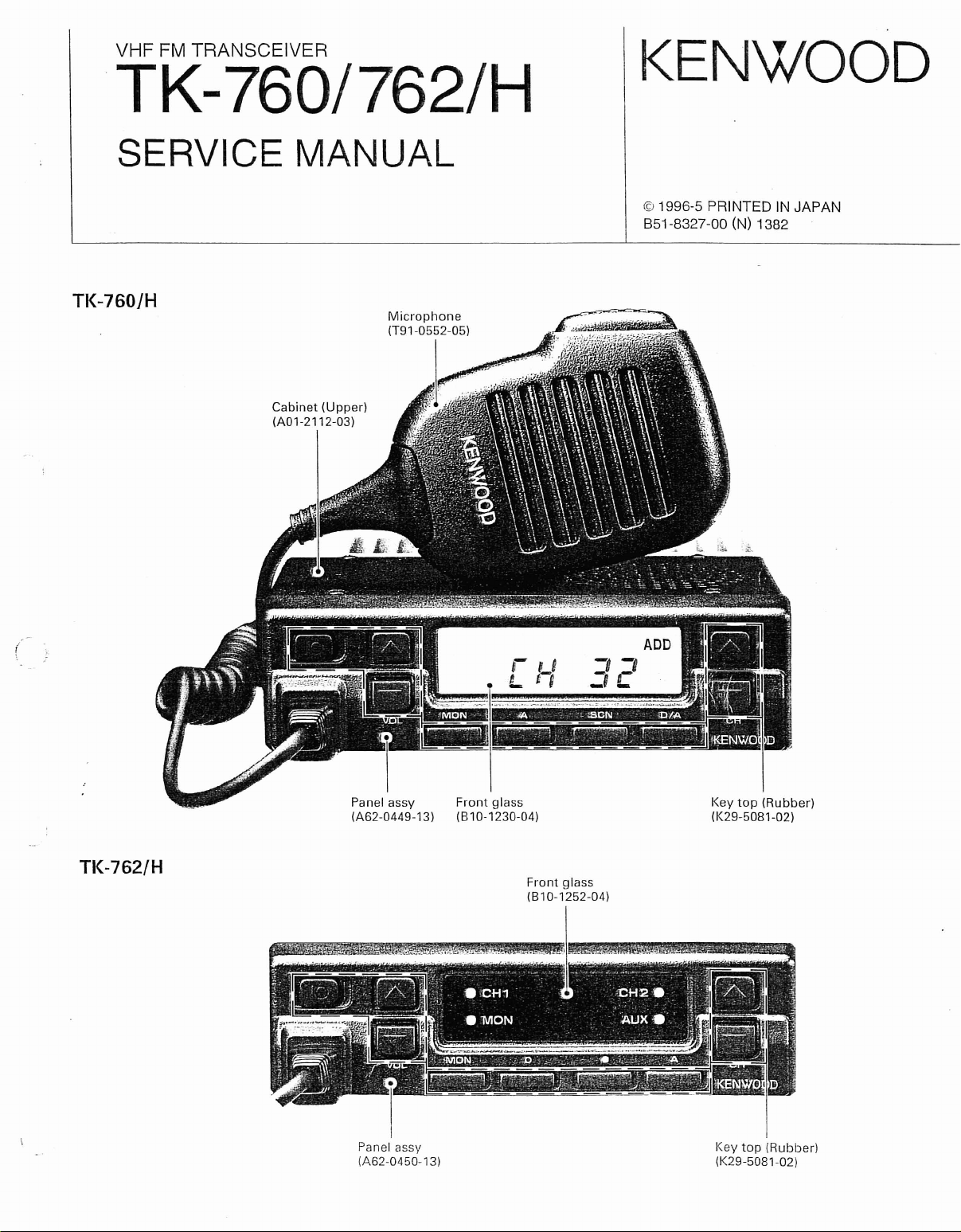
TK-760JH
Cabinet
(AOl-2112-03)
(
(Upper)
TK-762/H
Panel
(A62-0449-13)
-..."..;m:-
assy
Panel assy
(A62-0450-13)
Front
glass
(810-1230-04)
"-~-~
Front
glass
(810-1252-04)
Key
top
(K29-5081-02)
(Rubber)
Key
top
(K29-5081-02)
(Rubber)
TK-760/762/H
CONTENTS
GENERAL 3
SYSTEM SET-UP
OPERATING FEATURES
1.
Transceiver
INSTALLATION
1.
Accessory
2.
Ignition
3.
PA/HA
4.
DTMF
5.
External
6.
Fitting
REALIGNMENT
Modes
1.
2.
HowToEnter
3. Panel
4.
Panel
BLOCK
LEVEL DIAGRAM : 19
CIRCUIT DESCRIPTION
SEMICONDUCTOR DATA
DESCRIPTIONOFCOMPONENTS
PARTS LIST 34
EXPLODED VIEW
PACKING
ADJUSTMENT
TERMINAL FUNCTION
PC
KAP-1
SPECIFICATIONS BACK
DIAGRAM
Circuit
1.
2.
Receiving
3.
Transmitter
4.
Frequency
5.
Display
6.
Control
BOARD VIEWS I CIRCUIT DIAGRAMS
VCO (X58-4360-XX)
TX-RX
TX-RX
UNIT:
UNIT:
(PA/HA
Programming
Connection
Sense Cable (KCT-18 :
Unit
(KAP-1 :
Decode
Speaker 12
the
Control
Each
Test
Mode
Tuning
ConfigurationbyFrequency 20
Mode
System
System
Synthesizer
Section
Section
TX-RX (X57-4950-XX)
CONTROL (X57-4950-XX) (B/2) : TK-760 I (X57-5100-XX) (B/2) : TK-762
UNIT)
Cable (KCT-19 :
Option)
Option)
Panel
Upside
Mode
(TK-760 Only)
(TK-760 Only) 15
Unit
Down
(A/2):
Option)
:
TK-760 I (X57-5100-XX) (A/2) : TK-762
: 5
6
7
9
10
11
12
13
13
13
17
20
22
23
24
24
27
31
41
42
43
49
50
51
61
71
COVER
2

GENERAL
TK-760/762
INTRODUCTION
SCOPEOFTHIS
This manual is intended for use by experienced
technicians familiar
grade communications equipment. It contains
quired service information for the equipment and
currentasof the publication data. Changes which may
occur after publication are covered
Bulletins or Manual Revisions. These are issued
quired.
MANUAL
with
similar types of commercial
by
either Service
all
as
re-
re-
ORDERING REPLACEMENT PARTS
When ordering replacement parts or equipment information, the full part identification number should
included. This applies to
chassis. If the part number
chassis or kit number of which it
cient description
of
all
parts: components, kits, or
is
not known, include the
is
a part, and a suffi-
the required component for proper
identification.
FCC
COMPLIANCE
Model and Frequency TX
destination range (MHzl
TK-760
TK-760
TK-762
TK-762
TK-760H
TK-760H
TK-762H
TK-762H
K
K2
K
K2
K
K2
K
K2
AND
148-174
136-156
148-174
136-156
148-174
136-156
148-174
136-156
be
TYPE NUMBERS
power
IW)
25 5/2.5
25 5/2.5
25
25
45
45
45
45
is
Deviation
PERSONNEL SAFETY
The following precautions are recommended for
personnel
•
DO
meter) of the antenna.
•
DO
secure and any open connectors are properly terminated.
• SHUT
near electrical blasting caps orinan
mosphere.
• All equipment should
power-up for safe operation.
• This equipment should be serviced by a qualified
technician only.
(kHz)
5/2.5
5/2.5
5/2.5
5/2.5
5/2.5
5/2.5
safety:
NOT transmit if someoneiswithin
NOT transmit until
OFF
and DO NOT operate this
Signaling
OT DOT
0
0
0 0 0
0 0 0
allRFconnectors are verified
be
properly grounded before
2·TONE
DTMFENC
DEC
0 0 0 0
0 0 0 0
0 0 0 0
0 0
0 0
0 0
0
0
0
0
0
0
two
equipment
explosive at-
feet (0.6
PRE-INSTALLATION CONSIDERATIONS
1.
UNPACKING
Unpack the radio from its shipping container and
check for accessory items. If any
please contact KENWOOD immediately.
2.
L1CI;NSING REQUIREMENTS
Federal regulations require a station license for each
radio installation (mobile or base)
equipment owner. The licensee
suring transmitter power, frequency,
within the limits permitted by the station license.
Transmitter adjustments may
a licensed technician holding
general class commercial radiotelephone operator's
cense. Thereisno
license required to install or operate
the radio.
item
be
obtainedbythe
is
responsible for en-
and
deviation are
be
performed only by
an
FCC
first, second or
is missing,
3.
PRE-INSTALLATION CHECKOUT
3-1. Introduction
Each
radioisadjusted and tested before shipment.
However, it
mitter operation
is
recommended that receiver and trans-
be
checked for proper operation be-
fore installation.
3-2. Testing
The radio shouldbetested complete
and
accessoriesasthey will be connectedinthe final
installation.
power output should
sensitivity,
li-
OT
equipment operation shouldbeverified.
Transmitter
be
squelch
operation,
frequency,
checked,asshould receiver
with
deviation, and
and audio
all
cabling
output.
3
TK-760/762
4.
PLANNING THE
4-1. General
Inspect the vehicle and determine
the radio antenna and accessories will
Plan
cable runs for protection against pinching or
crushing wiring, and radio installation to prevent overheating.
INSTAllATION
how
be
mounted.
GENERAL
and where
5.
INSTALLATION PLANNING - CONTROL STATIONS
5-1. Antenna system
Control station. The antenna system selection depends
manual. Your KENWOOD dealer
an
needs.
on
many factors
antenna system that will best serve your particular
andisbeyond the scope of this
can
help you select
4-2. Antenna
The favored location for
of a large, flat conductive area, usually at the roof center. The trunk lid
vehicle chassis using ground straps to ensure the lid
at chassis ground.
4-3. Radio
The universal mount bracket allows the radio to
mountedina variety of ways.
is
surface
low
Position the radio close enough to the vehicle operator
to permit easy access to the controls when driving.
4-4. DC Power and wiring
1.
This radio maybeinstalledinnegative ground elec-
trical systems only. Reverse polarity will cause the
cable fuse to blow. Check the vehicle ground polar-
ity before installation to prevent wasted time
effort.
2.
Connect the positive power lead directly to the ve-
hicle battery positive terminal. Connecting the Posi-
tive lead to any other positive voltage source
vehicle
adequate to support the radio's weight. Al-
sufficient space around the radio for air cooling.
is
is
preferred, bond the trunk lid and
not recommended.
an
antennaisin
8e
the center
be
sure the mounting
and
in
the
5-2. Radio location
Select a convenient location for your control station
radio which
entry point. Secondly, use your system's power supply
is
(which supplies the voltage and current required for
your system). Make sure sufficient air
the radio and power supply to allow adequate cooling.
isascloseaspractical to the antenna cable
can
flow
around
SERVICE
This radioisdesigned for easy servicing. Refer to
the schematic diagrams, printed circuit board views,
and
alignment procedures containedinthis manual.
Note
When you modify your radioasdescribedinsystem
set-up, take the following precaution.
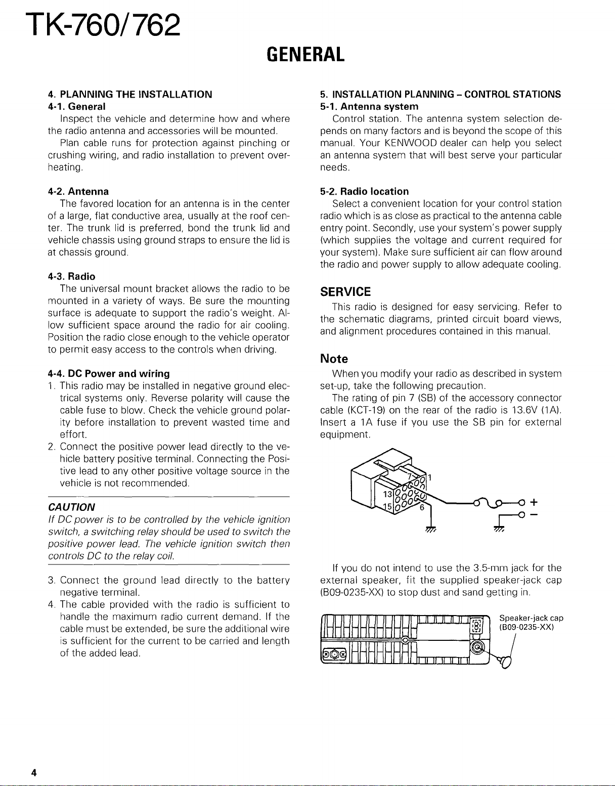
The rating of pin 7 (58) of the accessory connector
cable
(KCT-19)
Insert a 1A fuse if you use the
equipment.
on the rear of the radioisl3.6V
58
pin for external
(lA).
CAUTION
IfDCpoweristo be controlled by the vehicle ignition
switch, a switching relay should be usedtoswitch the
positive
controls DC to the relay coil.
3.
4.
power
Connect the ground lead directlytothe
negative terminal.
The cable provided
handle the maximum radio current demand. If the
cable must
is
sufficient for the current tobecarried
of
the added lead.
lead.
The
vehicle ignition switch then
with
the radioissufficient to
be
extended, be sure the additional wire
and
4
battery
length
If you do not intend to use the 3.5-mm jack for the
external speaker,
(809-0235-XX) to stop dust
fit
the
supplied speaker-jack cap
and
sand getting
in.
TK-760/762
(
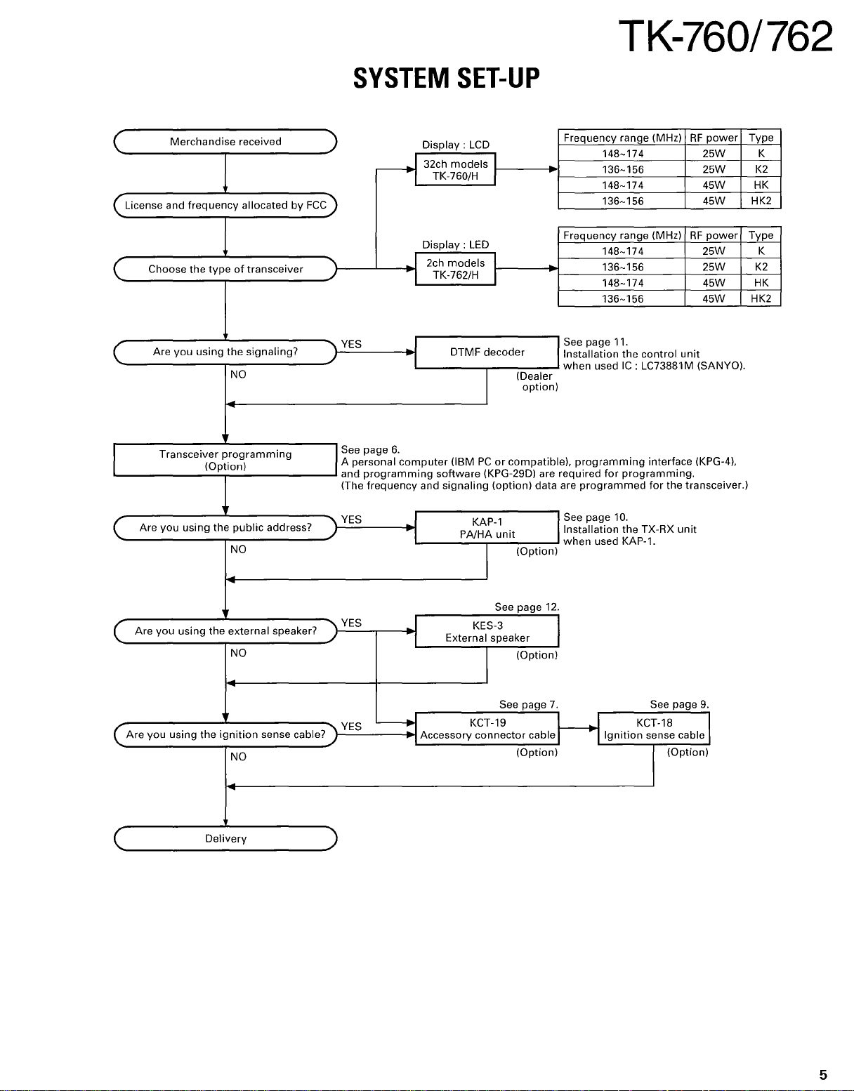
( License and
(
(
Merchandise
Choose
Are
Transceiver
I
frequency
the
typeoftransceiver
you
using
programming
(Option)
received
allocated by
the
signaling?
NO
FCC)
SYSTEM
)
-----.j
'\
./
""\
YES
./
ISee page
A personal
and
(The
6.
programming
frequency
Display:
32ch
TK-760/H I
Display:
I 2ch
TK-762/H
I
I
I
computer
and
SET-UP
LCD
models
models
DTMF decoder
(IBMPCor
software
signaling
I
LED
I
I
I
(KPG-29DI are required
(option) data are
(Dealer
option)
compatible),
Frequency range (MHz)RFpower
148-174
136-156
148-174
136-156
Frequency range (MHz)RFpower
148-174
136-156
148-174
136-156
See page 11.
Installation
when
programming
programmed
the
used
IC:
for
programming.
control
LC73881M (SANYO).
interface (KPG-4),
for
25W
25W
45W HK
45W
25W K
25W
45W
45W
unit
the transceiver.)
Type
K
K2
HK2
Type
K2
HK
HK2
Are
(
(
( .
you
Are you using
Are
you uSing t e
(
using the
the
h'
Delivery
public
address?
NO
external speaker?
NO
..
Ignition
sense
NO
'\
YES
./
J
I
KAP-l
PA/HA
unit
(Option)
See page 10.
Installation the TX-RX
when
used
KAP-l.
unit
I
See page 12.
""\
YES
./
I KES-3
External speaker
I
(Option)
I
cable
(Option)
7.
I KCT-18 I
I
Ignition
See page
YES
~
Accessory
bl 7
""\
ca
e.
./
KCT-19
connector
See page
sense cable
(Option)
9.
5
TK-760/762
OPERATING
1.
Transceiver Programming
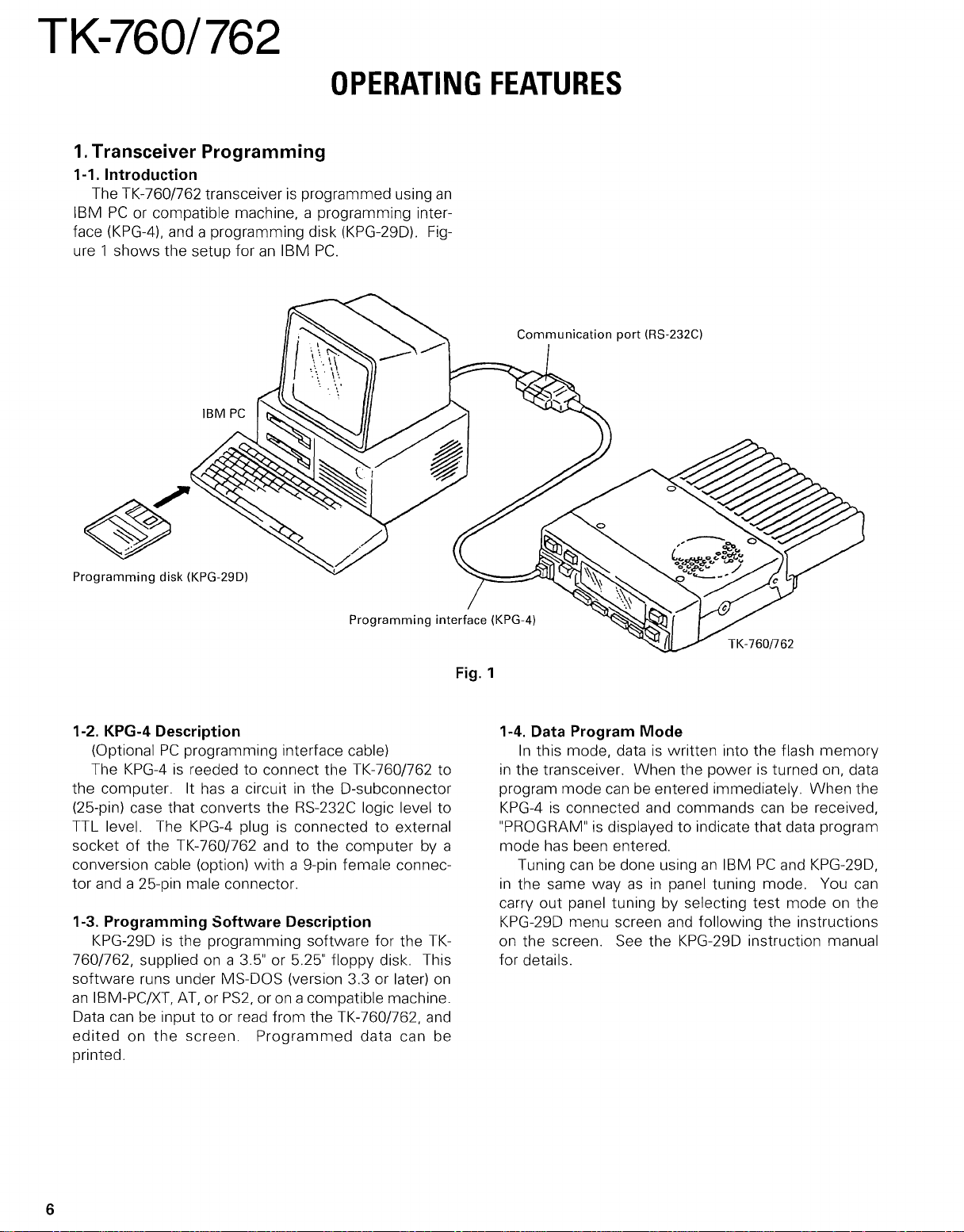
1-1. Introduction
The TK-760/762 transceiverisprogrammed using
IBMPCor compatible machine, a programming inter-
(KPG-4),
face
ure 1 shows the setup foranIBM
and a programming disk (KPG-29D).
PC.
Fig-
an
FEATURES
Communication
port
(RS-232Cl
Programming
1-2. KPG-4 Description
(OptionalPCprogramming interface cable)
The
the computer. It
(25-pin) case that converts the RS-232C logic level to
TTL level. The
socket of the TK-760/762 and to the computer
conversion cable (option)
tor and a 25-pin male connector.
1-3. Programming
KPG-29Disthe programming software for the
760/762, suppliedona 3.5" or 5.25" floppy disk. This
software runs under MS-DOS (version 3.3 or later)
an
IBM-PC/XT,
Data
can
edited
printed.
disk (KPG-29Dl
KPG-4isreeded to connect the TK-760/762 to
has
a circuitinthe D-subconnector
KPG-4
AT,orPS2,
be input to or read from the TK-760/762,
on
the
screen.
plugisconnected to external
with
a 9-pin female connec-
Software
Description
or on acompatible machine.
Programmed
data can be
by
TK-
on
and
Fig. 1
a
1-4. Data Program
In
this mode, dataiswritten into the flash memory
in
the transceiver. When the poweristurned on, data
program mode
KPG-4isconnected and commands
"PROGRAM"
mode
has
Tuning
in
the same wayasin
carry out panel tuning by selecting test mode on the
KPG-29D menu screen and following the instructions
on the screen. See the KPG-29D instruction manual
for details.
is
been entered.
canbedone usinganIBMPCand KPG-29D,
Mode
canbeentered immediately. When the
canbereceived,
displayed to indicate that data program
panel tuning mode. You
can
6
TK-760/762
OPERATING
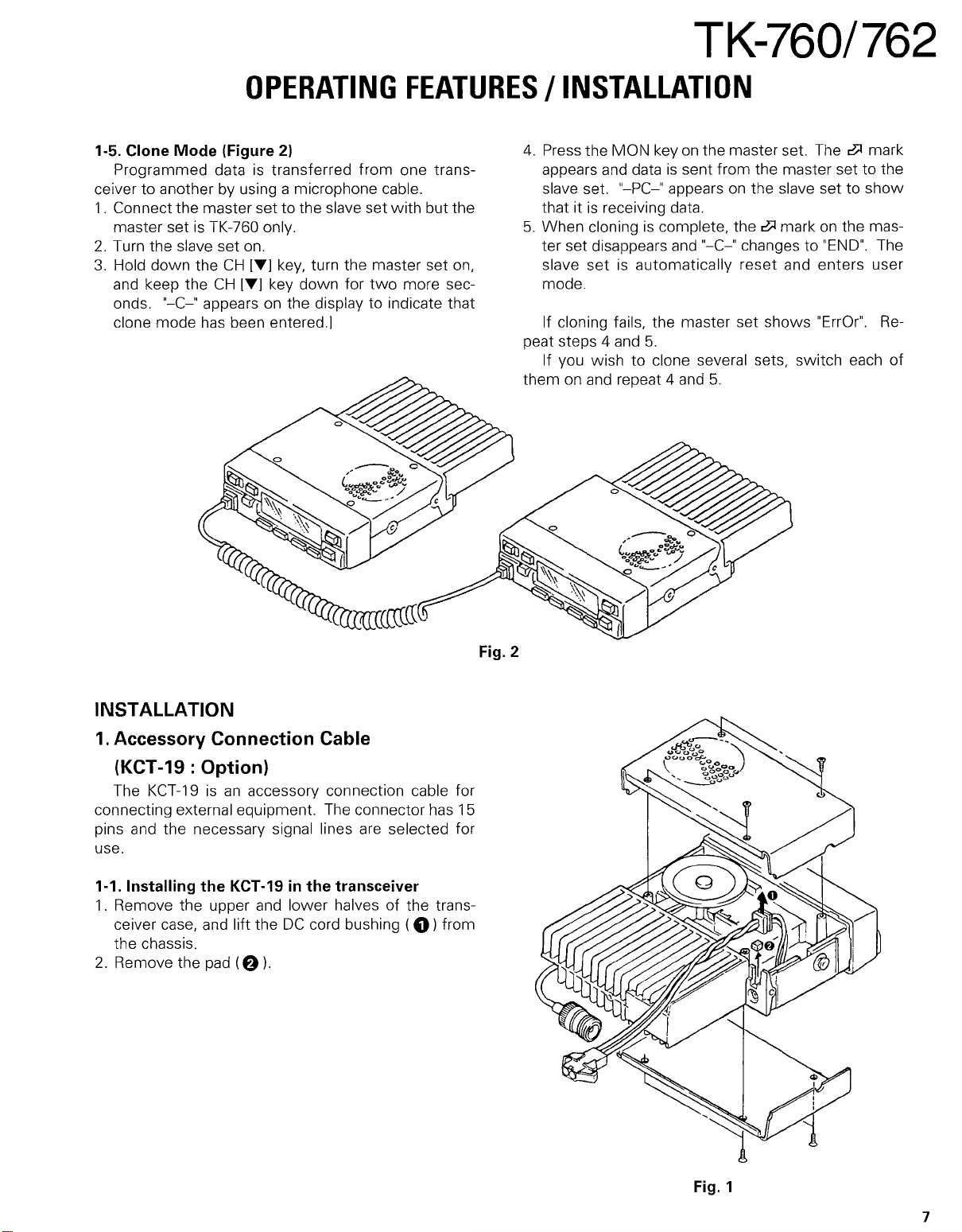
1-5. Clone
Programmed dataistransferred from one trans-
ceiver to another by using a microphone cable.
1.
Connect the master set to the slave set
master set
2.
Turn the slave set on.
3.
Hold down the
and keep the
onds. "-C-" appears on the display to indicate that
clone mode has been entered.]
Mode
is
TK-760 only.
(Figure
CH
CH
21
[Tj
key, turn the master set on,
[Tj key down for
FEATURES
with
two
more sec-
but the
/INSTALLATION
4.
Press the MON keyonthe master set. The~mark
appears and data
slave set. "-PC-" appears
that itisreceiving data.
5.
When cloningiscomplete, the~markonthe master set disappears
slave
setisautomatically reset and enters user
mode.
If cloning fails, the master set shows "ErrOr".
peat steps 4 and
If you wishtoclone several sets, switch each
them on and repeat 4 and
is
sent from the master settothe
on
the slave set to
and
"-C-" changes to
5.
5.
"END".
show
The
Re-
of
INSTALLATION
1.
Accessory Connection Cable
(KCT-19 : Option)
The KCT-19isan
connecting external equipment. The connector has
pins and the necessary signal lines are selected for
use.
1-1. Installing
1.
Remove the upper and lower halves of the trans-
ceiver case, and lift the
the chassis.
2.
Remove the pad
the
accessory connection cable for
KCT-19inthe
DC
(f)
I.
transceiver
cord bushing (
0)
15
from
Fig. 2
Fig. 1
7
TK-760/762
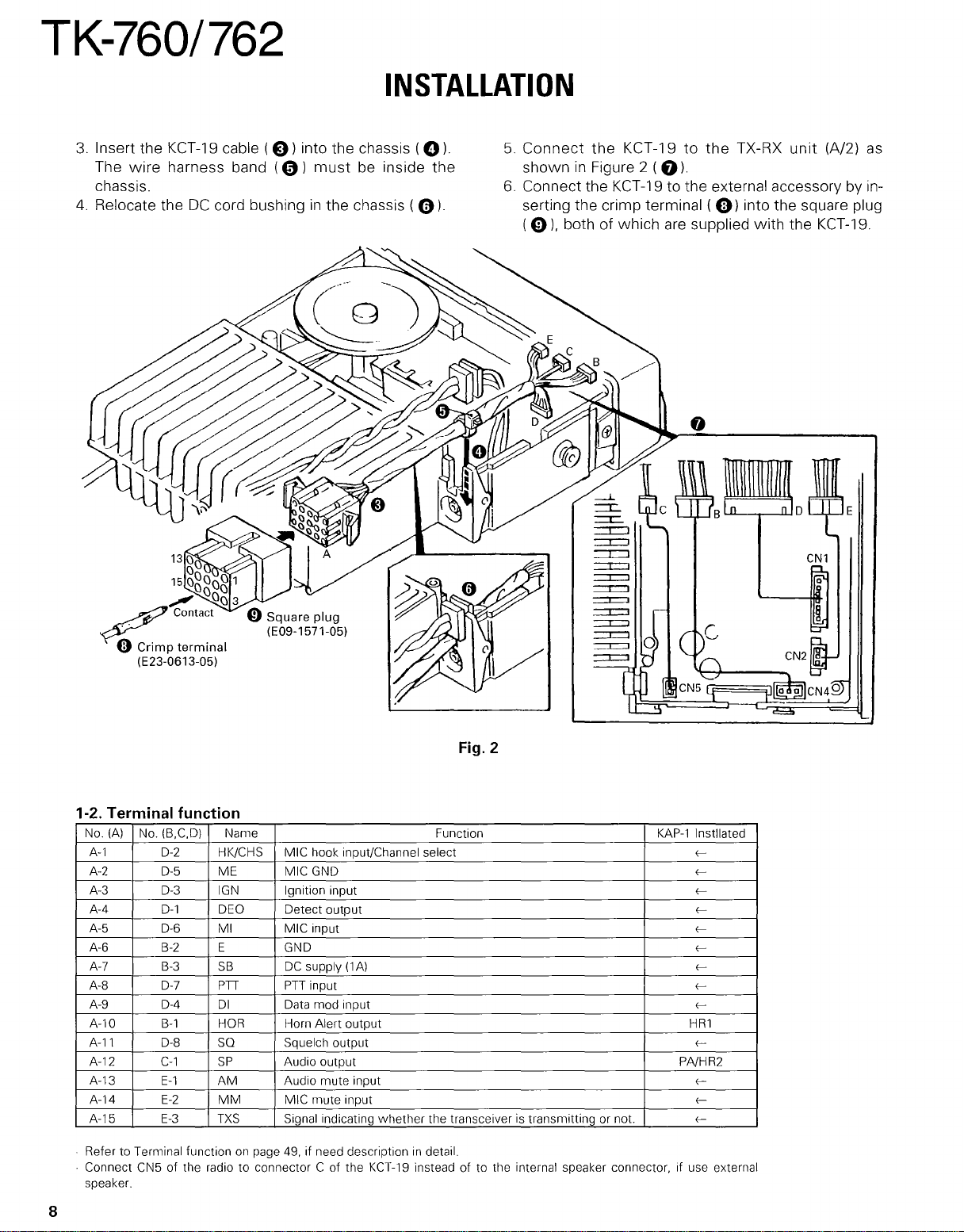
3.
Insert the
The
chassis.
4.
Relocate theDCcord bushinginthe chassis (
KCT-19
wire
harness band
cable
(e)
into the chassis
(0)
must
INSTALLATION
(0).
be inside the
0).
5.
Connect
showninFigure 2 (
6.
Connect the
serting the crimp terminal (
(0),
the
KCT-19tothe
KCT-19
both of which
TX-RX
unit
(A/2)
0).
to the external accessory by in-
9)
into the square plug
are
supplied
with
the
KCT-19.
as
1-2. Terminal function
No.
(A)
No.
(B,C.D)
A-1
A-2
A-3 0-3
A-4
A-5 0-6
A-6
A-7
A-S
A-9 0-4
A-10
A-l1
A-12
A-13
A-14
A-15
.
Refer to Terminal functiononpage 49, if need descriptionindetail.
Connect CN5 of the radio to connector C of the
.
speaker.
0-2
0-5
0-1
B-2
B-3
0-7
B-1
D-S
C-1
E-1
E-2
E-3
Name Function
HK/CHS MIC hook input/Channel select
ME MIC GND
IGN
DEO Detect output
MI MIC input
E GND
SB
PH
01
HOR
SO
SP
AM
MM
TXS
Ignition input
DC
supply
(1A)
PH
input
Data mod input
Horn Alert output
Squelch output
Audio output PNHR2
Audio mute input
MIC mute input
Signal indicating whether the transceiver is transmitting or not.
KCT-19
instead of to the internal speaker connector, if use external
Fig. 2
KAP-1
Instllated
<<<<<<<<<-
HR1
<-
<<<-
8
INSTALLATION
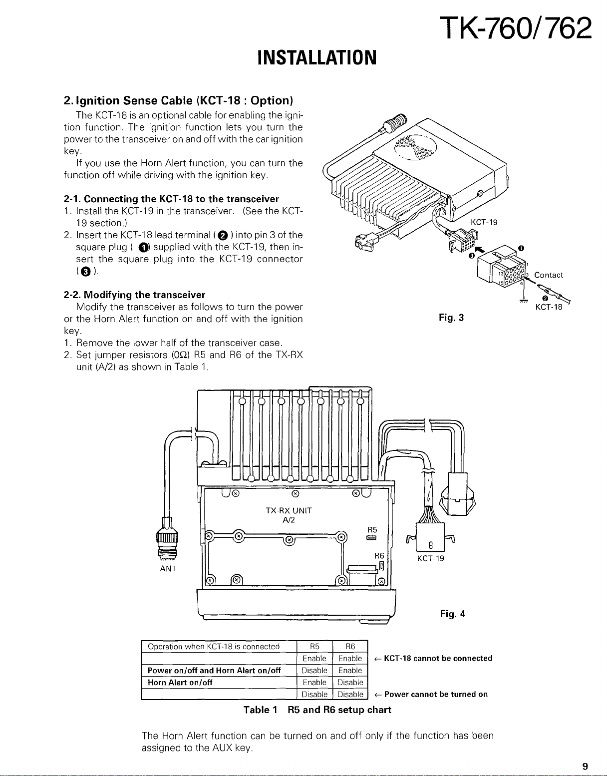
2.
Ignition
The
tion function. The ignition function lets you turn the
power
key.
If you use the Horn Alert function, you
function off while driving with the ignition key.
Sense Cable (KCT-18 : Option)
KCT-18isan
to the transceiver on
optional cable for enabling the igni-
and
off
with
the car ignition
can
turn the
TK-760/762
2-1. Connecting
1.
Install the
19 section.)
2.
Insert the KCT-18 lead terminal
square plug (
sert
the
(0)·
2-2. Modifying
Modify
or the Horn Alert function
key.
1.
Remove the lower halfofthe transceiver case.
2.
Set jumper resistors (On)
unit
the transceiverasfollows to turn the power
(A/2)asshowninTable
the
KCT
-18tothe
KCT-19inthe transceiver.
(f))
0) supplied
square plug into
the
transceiver
on
with
the
and
R5
1.
the
KCT-19
off
and
transceiver
(See
into pin 3 of the
KCT-19,
with the ignition
R6
of the
) )
Db
~
U0
~
~
ANT
~
t®1
the
KCT-
then in-
connector
TX-RX
) ) )
~
TX-RX
A/2
0
0
UNIT
0
~@
(011
@U
b
KCT-18
Fig. 3
i;==
"7
\\
[
~
.
t~
'--
R5
E;]
R6
10
tM
B
KCT-19
Fu
\
Operation
Power on/off and Horn Alert on/off
Horn Alert on/off
The Horn Alert function
assigned to the AUX key.
when
KCT-18isconnected
Table 1
can
R5 R6
Enable Enable
Disable Enable
Enable Disable
Disable Disable
R5
andR6setup chart
be turnedonand
j
~
KCT-18 cannot be connected
~
Power cannotbeturned
off
only if the function
Fig.
has
4
on
been
9
 Loading...