


 Loading...
MICRO COMPONENT SYSTEM
UX-A60V— Consists of CA-UXA60V and SP-UXA60V
 CA-UXA60V
 SP-UXA60V
|
|
|
VIDEO CD VERSION 2.0 |
|
|
REV.MODE |
|
COLOR |
DIMMER |
/REPEAT |
|
|
CLOCK |
PLAY |
SLEEP |
DISPLAY |
/TIMER |
MODE |
|
SET |
1 |
2 |
3 |
CANCEL |
4 |
5 |
6 |
ON |
7 |
8 |
9 |
SCREEN |
|||
DIGITAL |
10 |
0 |
+10 |
ECHO |
|||
|
FM MODE |
|
|
MPX |
STILL |
PBC |
RETURN |
|
|
|
MICRO COMPONENT SYSTEM UX-A60V |
SELECT |
FM/AM |
TAPE |
VIDEO |
CD |
/AUX/MD |
INTRO |
|
|
|
|
STANDBY/ON |
PREV. |
|
NEXT BEEP |
|
SOUND |
|
VOLUME |
|
MODE |
KARAOKE |
||
|
|
RM-SUXA60V |
|
MIN |
MAX |
PHONES |
MIC |
MIC |
LEVEL |
|
INSTRUCTIONS
For Customer Use:
Enter below the Model No. and Serial No. which are located either on the rear, bottom or side of the cabinet. Retain this information for future reference.
Model No.
Serial No.
GVT0075-003A
[UN,US]
Warnings, Cautions and Others
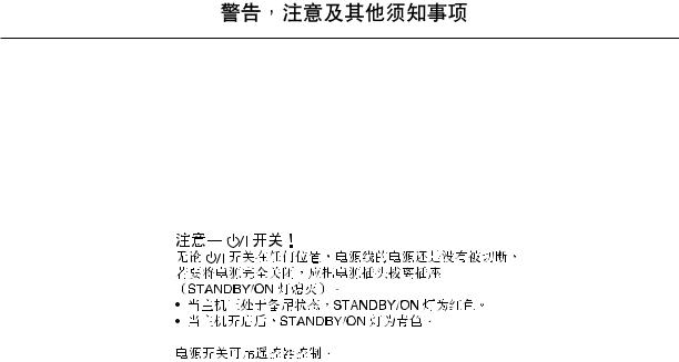
Caution ––  STANDBY/ON button!
Disconnect the mains plug to shut the power off completely (the STANDBY/ON lamp goes off).
The  STANDBY/ON button in any position does not disconnect the mains line.
•When the unit is on standby, the STANDBY/ON lamp lights red.
•When the unit is turned on, the STANDBY/ON lamp lights green.
The power can be remote controlled.
– G-1 –

English
CAUTION
To reduce the risk of electrical shocks, fire, etc.:
1.Do not remove screws, covers or cabinet.
2.Do not expose this appliance to rain or moisture.
CAUTION
•Do not block the ventilation openings or holes.
(If the ventilation openings or holes are blocked by a newspaper or cloth, etc., the heat may not be able to get out.)
•Do not place any naked flame sources, such as lighted candles, on the apparatus.
•When discarding batteries, environmental problems must be considered and local rules or laws governing the disposal of these batteries must be followed strictly.
•Do not expose this apparatus to rain, moisture, dripping or splashing and that no objects filled with liquids, such as vases, shall be placed on the apparatus.
– G-2 –
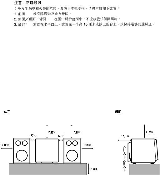
Caution: Proper Ventilation
To avoid risk of electric shock and fire, and to prevent damage, locate the apparatus as follows:
1 |
Front: |
No obstructions and open spacing. |
2 |
Sides/ Top/ Back: No obstructions should be placed in the areas shown by the dimensions |
|
|
|
below. |
3 |
Bottom: |
Place on the level surface. Maintain an adequate air path for ventilation by |
|
|
placing on a stand with a height of 10 cm or more. |
Front view |
Side view |
15 cm |
15 cm |
15 cm |
1 cm |
1 cm |
15 cm |
15 cm |
|
15 cm |
UX-A60V |
|
UX-A60V |
|
|
10 cm |
– G-3 –
English
IMPORTANT FOR LASER PRODUCTS /
REPRODUCTION OF LABELS / |
|
|
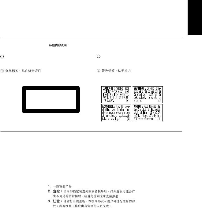
1 CLASSIFICATION LABEL, PLACED ON EXTERIOR |
2 WARNING LABEL, PLACED INSIDE THE UNIT |
|
SURFACE |
|
|
|
|
|
CLASS 1
LASER PRODUCT
1.CLASS 1 LASER PRODUCT
2.DANGER: Invisible laser radiation when open and interlock failed or defeated. Avoid direct exposure to beam.
3.CAUTION: Do not open the top cover. There are no user serviceable parts inside the unit; leave all servicing to qualified service personnel.
– G-4 –
English
Introduction
We would like to thank you for purchasing one of our JVC products. Before operating this unit, read this manual carefully and thoroughly to obtain the best possible performance from your unit, and retain this manual for future reference.
About This Manual
This manual is organized as follows:
•This manual mainly explains playback using the remote control, and the other operations such as recording operations using the buttons on the unit. You can use the buttons both on the remote control and on the unit for the same operations if they have the same or similar names (or marks), unless mentioned otherwise.
•Basic and common information that is the same for many functions is grouped in one place, and is not repeated in each procedure. For instance, we do not repeat the information about turning on/off the unit, setting the volume, changing the sound effects, and others, which are explained in the section “Basic and Common Operations” on pages 10 – 13.
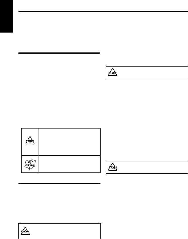
•The following marks are used in this manual:
Gives you warning and caution to prevent from damage or risk of fire/electric shock. Furthermore, gives you information which is not good for obtaining the best possible performance from the unit.
Gives you information and hints you had better know.
Precautions
Installation
•Install in a place which is level, dry and neither too hot nor too cold — between 5˚C and 35˚C.
•Install the unit in a location with adequate ventilation to prevent internal heat buildup in the unit.
•Leave sufficient distance between the unit and the TV.
•Keep the speakers away from the TV to avoid interference with TV.
DO NOT install the unit in a location near heat sources, or in a place subject to direct sunlight, excessive dust or vibration.
Power sources
•When unplugging the unit from the wall outlet, always pull the plug, not the AC power cord.
DO NOT handle the AC power cord with wet hands.
Moisture condensation
Moisture may condense on the lens inside the unit in the following cases:
•After starting heating in the room
•In a damp room
•If the unit is brought directly from a cold to a warm place Should this occur, the unit may malfunction. In this case, leave the unit turned on for a few hours until the moisture evaporates, unplug the AC power cord, then plug it in again.
Others
•Should any metallic object or liquid fall into the unit, unplug the AC power cord and consult your dealer before operating any further.
•If you are not going to operate the unit for an extended period of time, unplug the AC power cord from the wall outlet.
DO NOT disassemble the unit since there are no user serviceable parts inside.
If anything goes wrong, unplug the AC power cord and consult your dealer.
– 1 –

Contents
Location of the Buttons .................................. |
3 |
Main Unit ............................................................... |
3 |
Remote Control ...................................................... |
5 |
Getting Started ................................................ |
6 |
Unpacking .............................................................. |
6 |
Putting the Batteries into the Remote Control ......... |
6 |
Connecting Antennas .............................................. |
7 |
Connecting Speakers ............................................... |
8 |
Connecting Other Equipment .................................. |
8 |
Adjusting the Voltage Selector ................................ |
9 |
Basic and Common Operations ................... |
10 |
Turning On the Power ........................................... |
11 |
Selecting the Sources and Starting Play ................ |
11 |
Adjusting the Volume ............................................ |
12 |
Turning On/Off the Key-touch Tone ...................... |
12 |
Reinforcing the Bass Sound .................................. |
12 |
Selecting the Sound Modes ................................... |
12 |
Setting the Display Illumination ............................ |
13 |
Listening to FM and AM Broadcasts .......... |
14 |
Setting the AM Tuner Interval Spacing ................. |
15 |
Tuning in a Station ................................................ |
15 |
Presetting Stations ................................................ |
15 |
Tuning in a Preset Station ..................................... |
16 |
Playing Back Audio CDs .............................. |
17 |
Precautions on CD Playback ................................. |
18 |
Playing Back the Entire CD — Normal Play ........ |
18 |
Basic CD Operations ............................................ |
19 |
Programing the Playing Order of the Tracks |
|
—Program Play .............................................. |
20 |
Playing at Random—Random Play ....................... |
21 |
Repeating Tracks—Repeat Play ............................ |
21 |
Playing the Video CD Player (Video CDs) .. 22
Precautions on VCD Playback ............................. |
23 |
Setting the TV System ......................................... |
23 |
Playing Video CDs with the PBC Function ......... |
23 |
Playing Video CDs with the PBC Function |
|
without Using the Menu Screen |
|
(Continuous Play) .......................................... |
23 |
Playing Video CDs with the PBC Function |
|
Using the Menu Screen (Menu-Driven Play) 24 |
|
Playing Video CDs without the PBC Function .... |
25 |
Various Functions to Enhance Your Enjoyment ... |
25 |
MP3 Disc Playback .............................................. |
26 |
Basic Operations .................................................. |
26 |
Programming the Playing Order of the Tracks .... |
27 |
Playing Back Cassette Tapes ........................ |
28 |
Playing Back a Tape ............................................. |
29 |
Using External Equipment .......................... |
30 |
Listening to External Equipment ........................... |
31 |
Recording from This Unit |
|
to External Equipment .................................... |
31 |
Using the Microphone and Multiplex CDs . 32 |
|
Singing Along—Karaoke ...................................... |
33 |
Microphone Mixing .............................................. |
33 |
To Record Microphone Mixing on a Tape ............. |
34 |
Using the Multiplex CDs and Singing Along |
|
with Multiplex (MPX) Karaoke CDs .............. |
34 |
Recording on Tapes ...................................... |
35 |
Before You Start Recording ................................... |
36 |
Recording FM/AM Broadcasts ............................. |
37 |
Recording CD — CD Synchronized Recording .... |
37 |
Recording External Equipment ............................. |
38 |
Using the Timers ........................................... |
39 |
Setting the Clock ................................................... |
40 |
Using Recording Timer ......................................... |
40 |
Using Daily Timer ................................................ |
41 |
Using Sleep Timer ................................................ |
43 |
Timer Priority ....................................................... |
43 |
Maintenance .................................................. |
44 |
Troubleshooting ............................................ |
45 |
Specifications ................................................. |
46 |
English
– 2 –
English
Location of the Buttons
Become familiar with the buttons on your unit.
Main Unit
|
|
|
Top view |
|
|
|
|
|
|
|
|
|
|
|
|
1 |
|
|
|
|
|
|
|
|
e |
|
|
|
|
2 |
|
|
|
|
|
|
|
|
w |
|
|
|
|
|
|
|
F M / A M |
A U X / M D AHB PRO |
|
|
|
|
|
||
|
|
|
|
|
|
|
|
|
|
|
|||
|
|
|
|
STANDBY/ON COLOR |
|
MODE |
|
VOLUME |
|
q |
|
|
|
|
|
3 |
|
|
|
RETURN |
select |
REC start |
|
|
|
|
|
|
|
|
|
|
|
|
|
|
|
|
|
||
|
|
|
|
|
|
|
|
|
|
|
|
|
|
|
|
|
|
open/close |
CD SELECT |
PREV. |
|
NEXT |
T A P E open/close |
|
|
|
|
|
|
|
|
|
|
|
|
|
|
|
|
||
|
|
4 |
|
|
|
|
|
|
|
|
p |
|
|
|
|
5 |
|
|
|
|
|
|
|
|
9 |
|
|
|
|
|
|
|
6 |
7 |
|
8 |
|
|
|
|
|
Front view |
|
|
|
|
|
|
|
|
|
|
|
|
|
|
|
|
|
|
|
|
|
Display—indicators |
|
|
|
||
|
|
|
|
|
|
|
|
|
k |
j h |
g |
|
|
|
|
|
|
|
|
|
|
a |
PBC REC |
DAILY |
SOUND |
AHB |
GROUP |
r |
VIDEO CD VERSION 2.0 |
|
|
|
|
|
s |
|
ST MONO |
PRO |
|
||
|
|
|
|
|
|
|
|
|
|
||||
PBC REC DAIRY SOUND AHB |
|
|
|
|
|
|
|
|
|
|
|||
|
ST MONO |
PRO |
|
|
|
|
|
|
|
|
|
|
|
t |
|
|
|
|
|
|
|
d |
|
|
|
|
f |
|
|
|
|
|
|
|
|
|
|
|
|
|
|
|
MICRO COMPONENT SYSTEM UX-A60V |
|
|
|
|
|
|
|
|
|
|
|
|
|
|
STANDBY/ON |
|
|
|
|
|
|
|
|
|
|
|
|
|
|
|
|
; |
|
|
|
|
|
|
|
|
y |
|
|
MIN |
MAX |
|
|
|
|
|
|
|
|
|
PHONES |
|
|
|
MIC |
|
|
|
|
|
|
|
|
|
|
|
MIC |
|
LEVEL |
|
|
|
|
|
|
|
|
|
|
|
|
|
|
|
|
|
|
|
|
|
|
|
|
|
u |
i o |
|
|
|
|
|
|
|
|
|
|
|
|
|
|
|
|
|
– 3 – |
|
|
|
|
|
|
Continued
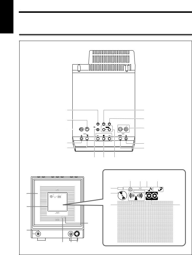
See pages in the parentheses for details.
Main unit |
Display—indicators |
1FM/AM button (11, 15)
•Pressing this button also turns on the unit.
2 COLOR button (9, 13)
3  STANDBY/ON button (11, 15)
4 CD open/close 0 button (18 – 20)
•Pressing this button also turns on the unit.
5 CD SELECT # ¥ 8 (play/pause) button (18, 24 – 26, 37)
•Pressing this button also turns on the unit.
6  RETURN button (24, 25)
7 Multi operation buttons
•PREV. 4 (reverse skip), 7 (stop), and ¢ NEXT
(forward skip)
8 MODE select and REC start buttons (37, 38)
9TAPE @ # (play) button (11, 29, 37, 38)
•Pressing this button also turns on the unit. p TAPE open/close 0 button (29)
•Pressing this button also turns on the unit. q VOLUME + / – buttons (12, 31)
w AHB (Active Hyper Bass) PRO button (12, 31) e AUX/MD button (11, 31, 38)
•Pressing this button also turns on the unit. r Electronic swing panel
t Display
•Shows the source name and some indicators, etc.
y PHONES ( ) jack—stereo mini-type (12) u Remote sensor
i MIC jack (33, 34)
o MIC LEVEL control (33, 34) ; STANDBY/ON lamp (11)
a PBC indicator (23 – 25)
sCD indicator
•Lights when CD is in the disc tray. d Tuner indicator
•Lights when the tuner is selected as the source. f Tape indicator
•Lights when a cassette is in the cassette loading slot. g AHB (Active Hyper Bass) PRO indicator (12)
h SOUND indicator (12)
j ST (stereo) and MONO indicators (15) k Timer mode indicators (40 – 43)
• (Timer), DAILY (Daily Timer), and REC (Recording Timer)
|
VIDEO CD VERSION 2.0 |
|
|
|
|
PBC REC |
DAIRY SOUND |
AHB |
|
|
|
|
ST MONO |
PRO |
|
|
|
MICRO COMPONENT SYSTEM UX-A60V |
|
|
|
||
|
|
STANDBY/ON |
|
|
|
PHONES |
|
|
|
|
|
|
|
|
|
|
3 |
|
|
MIC |
|
2 |
|
|
|
1 |
5 |
6 |
|
|
|
|
4 |
|
9 |
|
|
|
|
|
8 |
|
|
|
|
7 |
|
|
|
|
|
|
0 |
|
|
|
|
10 |
|
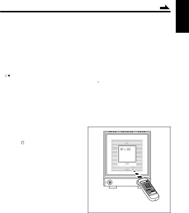
When using the remote control, point it at the remote sensor on the electronic swing panel.
English
– 4 –
English
Remote Control
1 |
|
|
|
|
h |
2 |
|
|
REV.MODE |
|
g |
COLOR |
DIMMER |
/REPEAT |
STANDBY/ON |
||
3 |
|
CLOCK |
PLAY |
SLEEP |
f |
DISPLAY /TIMER |
MODE |
||||
4 |
|
1 |
2 |
3 |
d |
5 |
SET |
|
|||
|
|
|
|
|
|
6 |
CANCEL |
4 |
5 |
6 |
|
|
|
|
|
|
|
|
ON |
7 |
8 |
9 |
s |
7 |
SCREEN |
||||
|
|
|
|
|
|
8 |
DIGITAL |
10 |
0 |
+10 |
|
ECHO |
|
||||
9 |
|
FM MODE |
|
a |
|
p |
MPX |
STILL |
PBC |
RETURN |
|
|
|
|
|
; |
|
q |
SELECT |
FM/AM |
TAPE |
VIDEO |
|
CD |
/AUX/MD |
INTRO |
o |
||
w |
|
|
|
|
|
PREV. |
|
NEXT BEEP |
i |
||
e |
|
|
|||
|
|
|
|
u |
|
|
SOUND |
|
|
|
|
|
KARAOKE |
VOLUME |
|
||
r |
MODE |
y |
|||
|
|
|
|
||
t |
|
|
|
|
|
|
|
|
RM-SUXA60V |
|
|
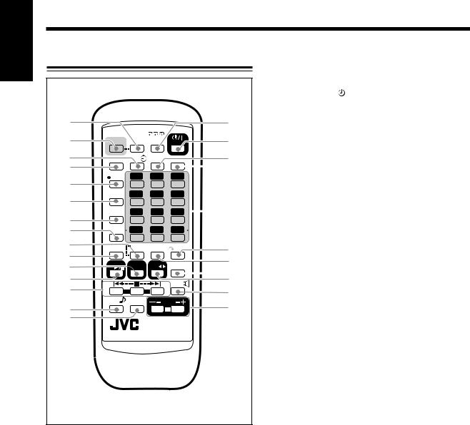
Remote control
1 |
DIMMER button (13, 40) |
2 |
COLOR button (9, 13) |
3 |
CLOCK/TIMER button (40 – 42) |
4 |
DISPLAY button (16, 19, 28, 31, 37, 38) |
5 |
SET button (13, 15, 16, 40 – 43) |
6 |
CANCEL button (20, 40, 41) |
7 |
ON SCREEN button (25) |
8 |
DIGITAL ECHO button (33, 34) |
9 |
FM MODE/STILL button (15 – 16) |
p MPX button (34)
q FM/AM/AUX/MD button (15, 16)
• Pressing this button also turns on the unit.
wSELECT CD 3 ¥ 8 (play/pause) button (11, 19 – 21, 23 – 24)
• Pressing this button also turns on the unit.
eMulti operation buttons
• PREV. 4 (reverse skip), 7 (stop), and ¢ NEXT
(forward skip)
r SOUND MODE button (12, 31) t KARAOKE button (33)
y VOLUME + / – buttons (12, 31) u BEEP button (12)
iTAPE 2 3 button (11, 29)
•Pressing this button also turns on the unit. o VIDEO INTRO button (11, 25)
; PBC button (24)
a  RETURN button (24) s Number buttons
•0, 1 – 10, +10 buttons
•+ / = buttons (13)
d SLEEP button (43)
f PLAY MODE button (20, 21)
g  STANDBY/ON button (11, 41, 42)
h REV. (reverse) MODE/REPEAT button (21, 25, 29)
– 5 –
Getting Started
Continued
Unpacking
Make sure that you have all the following items.
The number in parentheses indicates the quantity of the pieces supplied.
•FM antenna (1)
•AM loop antenna (1)
•AC power cord (1)
•Video cord (1)
•Remote control (1)
•Batteries (2)
•AC plug adaptor (1)
If anything is missing, consult your dealer immediately.
Putting the Batteries into the Remote Control
Insert the batteries—R6P(SUM-3)/AA(15F)—into the remote control, by matching the polarity (+ and –) on the batteries with the + and – marking on the battery compartment.
When the remote control can no longer operate the unit, replace both batteries at the same time.
1
2
R6P(SUM-3)/AA(15F)
3
•DO NOT use an old battery together with a new one.
• DO NOT use different types of batteries together.
•DO NOT expose batteries to heat or flame.
•DO NOT leave the batteries in the battery compartment when you are not going to use the remote control for an extended period of time. Otherwise, it will be damaged from battery leakage.
English
– 6 –
English
Connecting Antennas
FM antenna
A |
|
|
|
|
NT |
|
|
||
|
EN |
|
|
|
|
N |
|
||
|
|
A |
||
A |
|
|
||
|
M |
|
|
|
AM |
E |
XT |
||
LO |
||||
|
|
|
||
|
O |
P |
|
|
|
|
|
||
FM(75Ω |
) |
|||
C |
OAXI |
|
||
|
AL |
|||
FM antenna (supplied)
1Attach the FM antenna to the FM (75 Ω ) COAXIAL terminal.
2Extend the FM antenna.
3Fasten it up in the position which gives you the best reception.
About the supplied FM antenna
The FM antenna supplied with this unit can be used as temporary measure. If reception is poor, you can connect an outdoor FM antenna.
To connect an outdoor FM antenna
Before connecting it, disconnect the supplied FM antenna.
Outdoor FM antenna
(not supplied)
A |
|
|
|
|
NT |
|
|
|
|
|
EN |
|
|
|
|
|
N |
|
|
|
|
|
|
A |
AM |
AM |
EXT |
||
|
||||
|
LO |
|
|
|
|
|
O |
P |
|
|
|
|
|
|
FM(75Ω |
) |
|||
C |
OAXI |
|
||
|
|
AL |
||
A 75 Ω antenna with coaxial type connector should be used.
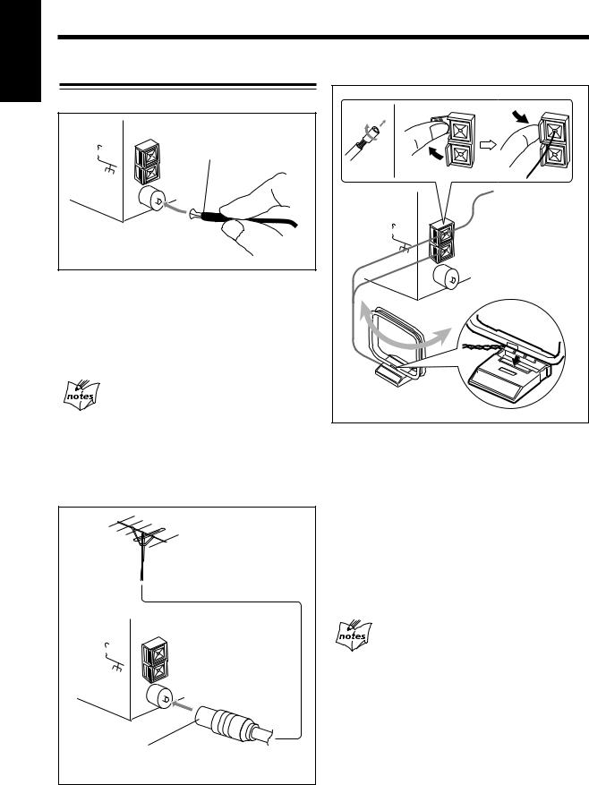
AM antenna
1 |
2 |
|
|
AM |
AM |
EXT |
|
|
|||
|
LOOP |
|
|
FM(75Ω |
) |
||
C |
OAXI |
||
|
|
AL |
|
AM |
|
|
|
(supplied) |
|||
1If cords are covered with insulation, twist the core of the cord at the end of each cord, then remove the insulation.
2Connect the AM loop antenna to the AM LOOP terminals as illustrated.
3Turn the AM loop antenna until you have the best reception.
To connect an outdoor AM antenna
When reception is poor, connect a single vinyl-covered wire to the AM EXT terminal and extend it horizontally. The AM loop antenna must remain connected.
For better reception of both FM and AM
•Make sure the antenna conductors do not touch any other terminals and connecting cords.
•Keep the antennas away from metallic parts of the unit, connecting cords, and the AC power cord.
– 7 –
Continued
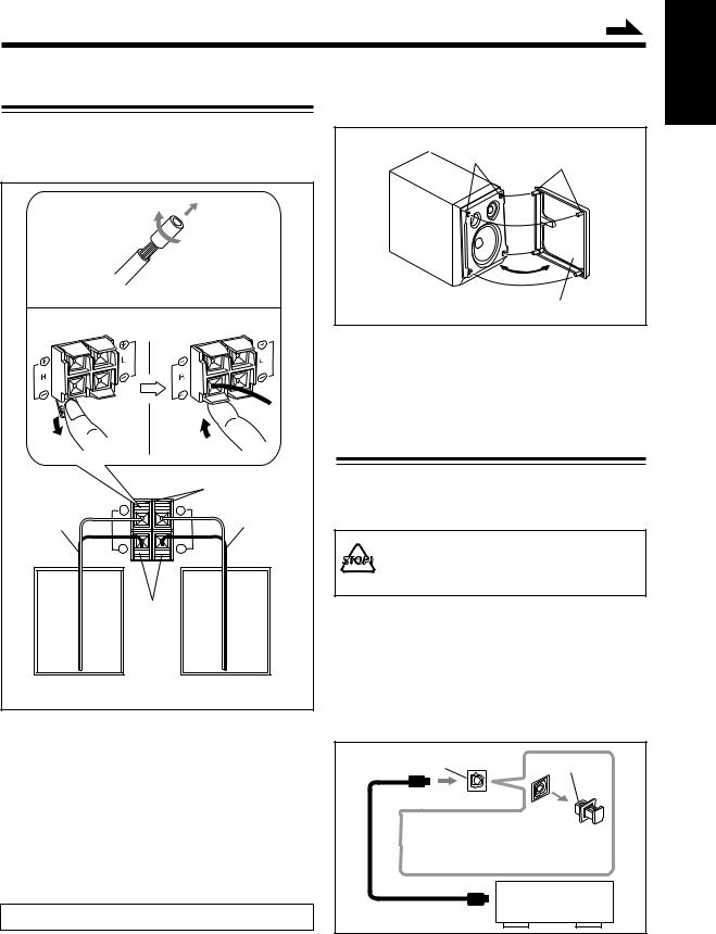
Connecting Speakers
To connect speakers
You can connect the speakers by following the procedure
below: |
|
|
|
|
1 |
|
|
|
|
2 |
Speaker terminals |
3,4 |
||
|
SPEAKER IMPEDANCE |
Red |
||
|
|
MIN 4Ω |
|
|
Speaker cord |
+ |
+ |
Speaker cord |
|
R |
L |
|||
|
||||
|
|
|||
|
– |
– |
|
|
|
|
Black |
|
|
|
R |
|
L |
|
Rear of the right |
Rear of the left |
|||
speaker |
|
speaker |
||
1If cords are covered with insulation, twist the core of the cord at the end of each cord, then remove the insulation.
2Open the speaker terminal.
3Insert the end of the speaker cord to the terminal.
Match the polarity: White cord to red (+) terminal and black cord to black (–) terminal.
4Close the speaker terminal on the rear of the unit.
USE ONLY SPEAKERS WITH THE SPEAKER IMPEDANCE — 4 Ω TO 16 Ω .
To remove the speaker grilles
The speaker grilles are removable.
Holes Projections
Speaker grille
To remove the speaker grille, insert your fingers at the top of the speaker grille, then pull towards you. Do the same at the bottom.
To attach the speaker grille, put the projections of the speaker grille into the holes of the speaker.
Connecting Other Equipment
You can connect both of the analog and digital equipment. When you connect and use the equipment, refer also to its manual supplied.
• DO NOT connect other equipment while the power is on.
•DO NOT plug in any equipment until all connections are complete.
To connect audio equipment with an optical digital input terminal
You can record CD sound onto the connected digital equipment.
Connect an optical digital cord (not supplied) between the optical digital input terminal on the other equipment and the OPTICAL DIGITAL OUT terminal.
OPTICAL DIGITAL OUT |
Protective cap |
|
terminal |
||
|
Before connecting the other equipment, remove the protective cap from the terminal.
Audio equipment with an optical digital input
English
– 8 –
English
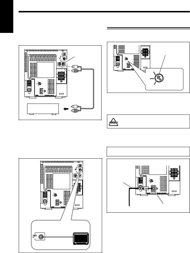
To connect analog audio equipment
Be sure that the plugs of the audio cords and the jacks on the rear of the unit are color-coded: White plugs and jacks are for left audio signals, and red ones for right audio signals.
|
|
LINE IN |
|
|
(AUX) |
|
R |
L |
|
SPEAKER IMPEDANCE |
|
|
MIN 4 |
|
|
R |
L |
230V |
|
|
|
VOLTAGE |
|
127V |
SELECTOR |
|
110V |
|
|
|
AC IN |
|
|
To output |
|
Analog audio |
|
|
equipment |
|
|
For playing the other equipment through this unit, connect between the audio output jacks on the other equipment and the LINE IN (AUX) jacks by using an audio cord (not supplied.)
To connect a TV set
You can connect a TV with a video input jack: used as a monitor for video CD playback.
|
R |
L |
|
SPEAKER IMPEDANCE |
|
|
MIN |
4 |
|
R |
L |
230V |
|
|
|
VOLTAGE |
|
127V |
SELECTOR |
|
110V |
|
|
|
AC IN |
|
Auxiliary Equipment
TV
To video input
Adjusting the Voltage Selector
Before plugging in the unit, set the correct voltage for your area with the voltage selector on the rear of the unit.
|
SPEAKER IMPEDANCE |
|
|
|
|
MIN 4 |
Voltage arrow |
|
R |
L |
|
230V |
|
|
|
|
VOLTAGE |
|
|
127V |
SELECTOR |
|
|
110V |
|
|
|
|
AC IN |
|
|
|
|
230V |
|
|
|
|
VOLTAGE |
|
|
127V |
SELECTOR |
|
|
110V |
|
Use a screwdriver to rotate the voltage selector so the voltage number the voltage arrow is pointing at is the same as the voltage where you are plugging in the unit. (See back cover page.)
DO NOT plug in before setting the voltage selector on the rear of the unit and all connection procedures are complete.
NOW, you can plug the AC power cord.
•If the wall outlet does not match the AC plug, use the supplied AC plug adaptor.
IMPORTANT: Be sure to check all connections to be done before plugging the AC power cord into a wall outlet.
|
|
SPEAKER IMPEDANCE |
|
|
|
|
MIN 4 |
|
|
R |
L |
AC power cord |
230V |
|
|
(supplied) |
SELECTOR |
|
|
127V |
|
||
|
|
VOLTAGE |
|
|
110V |
|
|
|
|
AC IN |
|
1 To the AC IN terminal
2 To a wall outlet
When connecting the AC power cord into a wall outlet, the unit automatically starts the display illumination.
To stop and cancel the display demonstration, press COLOR during display illumination—while the unit is turned off (on standby.)
To start the display illumination manually, press COLOR again while the unit is turned off (on standby.)
– 9 –

Basic and Common Operations
Continued
The buttons emphasized in the illustration below are used and explained in this section (pages 11 to 13.)
Remote control
COLOR DIMMER |
|
|
REV.MODE |
|
STANDBY/ON |
|
|
|
COLOR |
DIMMER |
/REPEAT |
STANDBY/ON |
|
|
|
||
|
DISPLAY |
CLOCK |
PLAY |
SLEEP |
|
|
|
|
|
/TIMER |
MODE |
|
|
|
|
||
|
SET |
1 |
2 |
3 |
|
|
|
|
SET |
|
4 |
5 |
6 |
|
|
|
|
|
CANCEL |
|
|
|
|
|||
|
ON |
7 |
8 |
9 |
|
|
|
|
|
SCREEN |
|
|
|
|
|||
|
DIGITAL |
10 |
0 |
+10 |
|
|
|
|
|
ECHO |
|
|
|
|
|||
|
MPX |
FM MODE |
RETURN |
10 |
0 |
+10 |
|
|
|
STILL |
PBC |
|
|||||
|
SELECT |
FM/AM |
TAPE |
VIDEO |
|
|
|
|
|
CD |
/AUX/MD |
INTRO |
|
|
|
|
|
|
PREV. |
|
NEXT BEEP |
SELECT |
FM/AM |
|
VIDEO |
|
|
|
|
|
|
TAPE |
|||
|
SOUND |
|
|
|
CD |
/AUX/MD |
INTRO |
|
|
|
VOLUME |
|
|
|
|
||
|
MODE |
KARAOKE |
|
|
|
|
||
|
|
|
|
|
PREV. |
|
|
NEXT BEEP |
|
|
|
RM-SUXA60V |
|
|
|
|
|
|
|
|
|
|
SOUND |
|
|
VOLUME |
|
|
|
|
|
MODE |
KARAOKE |
|
|
Main unit (Top view)
Main unit (Front view)
|
|
F M / A M |
A U X / M D AHB PRO |
|
|
STANDBY/ON |
COLOR |
RETURN |
MODE |
VOLUME |
|
|
|
select REC start |
|
|
|
open/close |
CD SELECT |
PREV. |
NEXT |
T A P E |
open/close |
STANDBY/ON |
MIN |
MAX |
PHONES |
MIC |
|
|
MIC |
LEVEL |
|
English
– 10 –
English
Turning On the Power |
|
Selecting the Sources and Starting Play |
|
|
|
When you press the play buttons (SELECT CD 3 / 8, TAPE 2 3) for a particular source or FM/AM or AUX/ MD button on the main unit, the unit automatically turns on (and starts playback if the source is ready.)
To turn on the unit without playing, press  STANDBY/ON.
The STANDBY/ON lamp on the electronic swing panel lights green.
To turn off the unit (on standby), press  STANDBY/ON again.
The STANDBY/ON lamp on the electronic swing panel lights red.
•“0:00” appears on the display until you set the
built-in clock. After setting the clock, the clock time will appear on the display while the unit is turned off (on standby.)
•A little power is always consumed even while the unit is on standby.
To set the built-in clock, see page 40.
To switch off the power supply completely, unplug the AC power cord from the AC outlet.
When you unplug the AC power cord or if a power
failure occurs
The clock setting, the tuner preset stations and other settings will be erased.
To select the tuner or external equipment, press FM/ AM/AUX/MD.
The unit automatically turns on (when the unit is on standby) and the last selected source appears on the display.
•Each time you press the button, the sources change as follows:
 FM
FM  AM
AM
(TUNER)
AUX 
•When you change the source from the others, “TUNER” appears for a while.
•For more detailed tuner operations, see pages 14 to 16.
•For operating the external equipment, see the manuals supplied with them.
When using the main unit:
•Press FM/AM to select the tuner.
–Each time you press the button, the band alternates between FM and AM.
•Press AUX to select the external equipment.
To select the CD player, press CD SELECT # / 8. The unit automatically turns on (when the unit is on
standby), and “CD” appears on the display. Play will start if a CD is on the disc tray. (“NO DISC” will appear on the display if a CD is not loaded.)
To stop playback, press 7.
• For more detailed operations, see page 18 .
To select the cassette deck, press TAPE @ #.
The unit automatically turns on (when the unit is on standby), and “TAPE” appears on the display. Play will start if a cassette is in the cassette loading slot. (“NO TAPE” will appear on the display if a cassette is not in the cassette loading slot.)
To stop playback, press 7.
• For more detailed operations, see pages 28 and 29.
To select external equipment, press FM/AM/AUX/MD. The unit automatically turns on (when the unit is on standby), and “AUX” appears on the display.
•For more detailed operations, see pages 15 and 16.
•For operating the external equipment, see the manuals supplied with them.
– 11 –
Loading...