


FIXED DOME CAMERA
TK-C2201U |
|
|
|
INSTRUCTIONS |
||||||||||||
TK-C2201E |
|
|
|
|
|
|
|
|
|
|
|
|||||
|
|
|
|
|
|
|
|
|
|
|
|
|
|
|
|
|
|
|
|
|
|
|
|
|
|
|
|
|
|
|
|
|
|
|
|
|
|
|
|
|
|
|
|
|
|
|
|
|
|
|
|
|
|
|
|
|
|
|
|
|
|
|
|
|
|
|
|
|
|
|
|
|
|
|
|
|
|
|
|
|
|
|
|
|
|
|
|
|
|
|
|
|
|
|
|
|
|
|
|
|
|
|
|
|
|
|
|
|
|
|
|
|
|
|
|
|
|
|
FOR CUSTOMER USE:
Enter below the Serial No. which is located on the body. Retain this information for future reference.
Model No. TK-C2201U,TK-C2201E
Serial No.
.
LST0952-001A

Introduction |
|
Contents |
|
Introduction |
|
Contents ............................................................................................................. |
2 |
Features ............................................................................................................. |
3 |
Operating Precautions ....................................................................................... |
4 |
Name of Parts .................................................................................................... |
6 |
Setup |
|
Setting the Switches .......................................................................................... |
9 |
About Connection Cables ................................................................................ |
10 |
Installation |
|
Mounting the Camera ...................................................................................... |
12 |
Adjustment |
|
Adjusting Image ............................................................................................... |
17 |
Adjusting the Auto White Balance .................................................................... |
22 |
Mounting the Dome Cover ............................................................................... |
23 |
Others |
|
Specifications ................................................................................................... |
25 |
2
Introduction
Thank you for purchasing this product.
Before use, please read this "INSTRUCTIONS" and the information materials included to ensure proper use of this product.
These instructions are for TK-C2201U/TK-C2201E.
Features
vEasy DAY/NIGHT function
v3D noise reduction (3DNR)
v4 areas privacy mask
vBuilt-in display mode (CRT or LCD selectable)
How to read this manual
Conventions and symbols
Note : Indicates operating precautions.
Memo : Indicates reference data regarding limitations on functions, usage and the like.
A : Indicates a reference page or item. Contents of this manual
vJVC holds the copyright to this manual. Any part or all of this manual may not be reproduced without prior consent from the company.
vProduct names of other companies described in this manual are trademarks
or registered trademarks of the respective companies. Symbols such as , ,
E T
and are omitted in this manual.
R
vDesign, specifications and other contents described in this manual are subject to change for improvements without prior notice.
3

Introduction
Operating Precautions
m Storage and Location of Use
vThis camera has been designed for indoor use. It cannot be used outdoors.
vDo not install the camera in the following places.
-In a place exposed to rain or moisture.
-In a place with vapor or oil, for example in a kitchen.
-When the ambient temperature rises above or falls below the acceptable range (from -10 f to 50 f)
-In a place at which corrosive gases are emitted.
-Near a source of radiation, X-rays, strong radio waves or magnetism.
-In a place subject to vibration.
-In a place with excessive dirt.
vUsing this unit in the vicinity of the transmitting antenna of a radio or TV, devices that emit strong electromagnetic waves such as a transformer or motor, or wireless devices such as a transistor or mobile phone may give rise to noises in the image and changes in its color.
vDo not install in an environment where there is cold air or near the air outlet of an air conditioner. The dome cover may become foggy as a result of sudden temperature changes.
m Maintenance
v Clean the dome cover lens using a lens wiper cloth (or a tissue). For tough stains, wipe with a neutral detergent diluted with water, followed by wiping with a dry cloth. Do not use benzene or thinner to wipe the camera. Doing so may melt the surface or cause it to fog.
m Energy Conservation
v When the camera is not in use for a long time, turn off the power for safety and energy conservation reasons.
m Copyright Protection
vWith the exception of the user being the copyright holder or when permission such as for duplication has been granted by the copyright holder, permission is required in principle for the duplication, modification, or transmission of copyrighted material.
vUnauthorized duplication, modification, or transmission of copyrighted material may constitute a copyright infringement, and the user may be liable to compensate for any damages. When using copyrighted material, be sure to check the license agreement of the copyrighted material thoroughly.
vWhen rights or rights holders are involved with regard to the targeted duplicating subject, permission may be required for shooting or using (processing) it. Be sure to check the licensing conditions thoroughly.
4

Introduction
m Disclaimer
v We will not be responsible for any inconveniences or disturbances caused in the event of privacy invasion as a result of camera footages of this product.
m Others
vWhen using this camera with [AGC] set to "MID" or "HIGH", the sensitivity increases automatically for dark images and the screen may appear grainy, but this is not a malfunction.
vIf the Easy DAY/NIGHT switch is turned to "AUTO", the mode changes automatically to black and white in dark places. As the sensitivity level is increased in this case, the screen may appear grainy and more white spots may appear. When switching between modes, the brighter area on the screen is emphasized and visibility may be reduced. However, this is not a malfunction.
vWhen shooting an extremely bright object (e.g. lamp), the image on the screen may have white vertical tailings (smear) or expansion (blooming) may appear around it. This is a characteristic of the CCD and not a malfunction.
vWhen the white balance of this camera is set to "ATW-N" or "ATW-W" and depending on the conditions of the object, the color tone may differ slightly from the actual color due to the principle of the automatic tracking white balance circuit. This is not a malfunction.
vWhen this camera is used under high temperatures, vertical stripes may appear on the screen. This is a characteristic of the CCD and not a malfunction.
vWhen this camera is moved from a cold to warm place, condensation may occur and the camera may not work. In this case, leave the camera under room temperature for about one hour before turning on the power.
vWhen the power supply voltage is momentarily disrupted or drops due to lightning, turning on the air-conditioner or the like, image distortion or noise may occur.
vWhen the power supply voltage of the camera drops, the input protection circuit inside the camera operates, and the camera may be turned off. Make use of a
voltage rating within 10 % for the camera’s power supply voltage.
5
v This unit enlarges the rotation angle to support wide range set up. When the
zoom of the lens is set to WIDE end and the tilt angle is set around 80 , the
5 7 dome cover can be visible into the image depending on the rotation angle. In this case, adjust the image angle if necessary. (A page 18)
vThe 3D noise reduction function of this camera may result in afterimage of a moving subject. Afterimage is more likely to occur when using the camera with [DNR LEVEL] set to "HIGH". This is not a malfunction.
5

Introduction
Name of Parts
Camera (Interior)
The dome cover and inner dome are removed.
Refer to "Mounting the camera directly to the ceiling or on the wall" (A page 13) step 2 to 3 on the removal methods.
A |
G |
B |
|
C |
|
D |
|
E |
|
F |
|
H

 I
I 

 J
J
|
K |
F. |
L |
|
|
ADJ |
M |
|
|
|
MENU |
SET |
N |
|
A Focus Adjustment Ring
(A page 19)
B Zoom Adjustment Ring
(A page 19)
C Fall Prevention Sheet
(A page 13)
D Rotation Knob
(A page 18)
E [MONITOR] Terminal (RCA pin)
(A page 17)
6

Introduction
F Tilt Fastening Screw
(A page 18)
G Focus Adjust Gear
(A page 19)
H Shooting Direction Mark
(A page 15) (A page 18)
I Pan Center Mark
(A page 18)
J Rotation Center Mark
(A page 18)
K Function Selection Switches
(A page 9)
L [MENU] Button
Display the menu screen.
Refer to the attached manual "MENU SETTING" for more details about setting the menu.
M Status Indication Lamp
Lights up when the power is turned on.
N [J, K, H, I]/[SET] Button
This allows user to select menu screens and change or confirm settings. Fine Focus Adjustment (A page 20)
Auto White Balance Adjustment (A page 22)
7

Introduction
Name of Parts (Continued)
Camera
 D
D
 E
E
 F
F
A
 G
G
H
B C
A Mounting Hole 2
2
(A page 15)
B Dome Cover
(A page 13)
C Inner Dome
(A page 13)
D Video Signal Output Connector (BNC)
(A page 14)
E Protection Cover
(A page 14)
F Power Supply Cable
(A page 11)
G Wiring Hole
(A page 16)
H Fall Prevention Wire Mounting Screw
(A page 14)
8
Setup
Setting the Switches
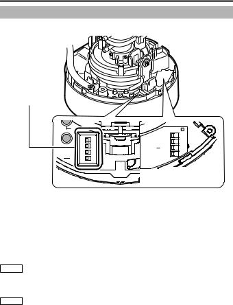
Before mounting the camera, set the function setting switches on the camera. To set the switches, use a fine-tipped screwdriver.
Function selection switches
.F
ADJ
 MENU
MENU
|
|
DIP SW |
|
D/N AUTO 1 |
OFF |
|
BLC OFF 2 |
ON |
MONITOR LCD 3 |
CRT |
|
TYPE |
NOT USED 4 |
|
|
|
|
SEE INSTRUCTION |
MANUAL |
 DIP Switch Settings Chart
1 [D/N AUTO/OFF] Easy Day & Night Switch
Set this to "AUTO" when shooting a subject with continually changing brightness (day/night). The image switches to color when the subject is bright, and black and white when it is dark. The image is set to color at all times when "OFF" is selected. (Default setting: AUTO)
2 [BLC OFF/ON] Backlight Compensation Selector Switch
Set this to "ON" when shooting in backlight. The subject becomes easier to see as brightness is adjusted according to the photometry area set in [BLC AREA] of the menu.
(Default setting: OFF)
Memo Refer to [BLC AREA] in the "MENU SETTING" (separate).
3 [MONITOR TYPE LCD/CRT] Monitor Type Selector Switch
Set this to "LCD" or "CRT" according to the monitor in use. (Default setting: LCD)
Memo Refer to [LCD TYPE] in the "MENU SETTING" (separate).
9
 Loading...