


COMPACT VHS CAMCORDER
GR-AX460 GR-AX360 GR-AX260
ENGLISH
Compact VHS
PAL
(GR-AX460 shown)
INSTRUCTIONS
YU30052-562-1
2


Dear Customer,
Thank you for purchasing the JVC Compact VHS camcorder. Before use, please read the safety information and precautions contained in the following pages to ensure safe use of your new camcorder.
Using This Instruction Manual
•All major sections and subsections are listed in the Table Of Contents (Z pg. 3).
•Notes appear after most subsections. Be sure to read these as well.
•Basic and advanced features/operation are separated for easier reference.
Warning on lithium battery
The battery used in this device may present a fire or chemical burn hazard if mistreated. Do not recharge, disassemble, heat above 100°C or incinerate.
Replace battery with Panasonic (Matsushita Electric), Sanyo or Maxell CR2025; use of another battery may present a risk of fire or explosion.
nDispose of used battery promptly.
nKeep away from children.
nDo not disassemble and do not dispose of in fire.
It is recommended that you . . .
.... refer to the Index (Z pgs. 36, 37) and familiarize yourself with button locations, etc. before use.
.... read thoroughly the Safety Precautions that follow and cautions (Z pgs. 38, 39). They contain extremely important information regarding the safe use of your new camcorder.
SAFETY PRECAUTIONS
WARNING:
TO PREVENT FIRE OR SHOCK HAZARD, DO NOT EXPOSE THIS UNIT TO RAIN OR MOISTURE.
Crossed Out Dust Bin Mark
n The Crossed Out Dust Bin Mark on the battery pack indicates that the product complies with Directives 91/157/EEC and 93/86/ EEC.
n Nickel-Cadmium (Ni-Cd) battery pack must be recycled or disposed of properly.
This camcorder is designed to be used with PAL-type colour television signals. It cannot be used for playback with a television of a different standard. However, live recording is possible anywhere. Use the BN-V12U/V22U/V25U battery packs and, to recharge them, the provided multi-voltage AC Power Adapter/ Charger. (An appropriate conversion adapter may be necessary to accommodate different designs of AC outlets in different countries.)
CAUTIONS:
nTo prevent shock, do not open the cabinet. No user serviceable parts inside. Refer servicing to qualified personnel.
nWhen you are not using the AC Power Adapter/Battery charger for a long period of time, it is recommended that you disconnect the power cord from AC outlet.
PAL
nCamcorder is designed exclusively for the VHS-C video cassette. Only cassettes marked VHS-C can be used with this unit.
nHQ VHS is compatible with existing VHS equipment.
NOTES:
cThe rating plate (serial number plate) and safety caution are on the bottom and/or the back of the main unit.
cThe rating plate (serial number plate) of the AC Power Adapter/Charger is on its bottom.
This unit is produced to comply with Standard IEC Publ. 65.

MAJOR FEATURES
nProgramme AE with Special Effects (Z pg. 14)
nIntelligent Function Control (Z pg. 16 – 23)
n14x Variable-Speed Hyper Zoom (Z pg. 11)
nEasyEdit (Random Assemble
Editing) (Z pg. 30 – 33) n Desigh-Integrated
Auto Light (GR-AX460 only) (Z pg. 13)
REMEMBER
The Logical Choice
PAL
 The only compact video cassettes that can be
used with your VHS VCR*
PROVIDED ACCESSORIES
• AC Power Adapter/ |
•Battery Pack |
Charger AA-V11EG |
BN-V12U |
• Cassette Adapter C-P7U |
•Shoulder Strap |
|
|
• Lithium Battery CR2025 |
|
|
•Cable adapter |
• Editing cable |
|
CONTENTS |
3 |
GETTING STARTED |
4 |
Power ............................................ |
4 |
Clock (Lithium) Battery |
|
Removal/Insertion ............................. |
6 |
Date/Time Settings ............................ |
6 |
Viewfinder Adjustment ........................ |
7 |
Tape Length Setting ............................ |
7 |
Loading/Unloading A Cassette ............... |
7 |
Grip Adjustment ................................ |
8 |
Shoulder Strap Attachment ................... |
8 |
Tripod Mounting ................................ |
8 |
Remote Control Unit ........................... |
9 |
RECORDING |
10 |
Basic Recording ............................... |
10 |
Basic Features ................................ |
11 |
Advanced Features ........................... |
13 |
PLAYBACK |
26 |
Using The Cassette Adapter ................ |
26 |
Basic Connections ............................. |
27 |
Basic Playback ................................ |
28 |
Features ....................................... |
29 |
EDITING |
30 |
Tape Dubbing .................................. |
30 |
Random Assemble Editing (R.A.Edit) ...... |
30 |
Insert Editing .................................. |
34 |
Audio Dubbing ................................ |
35 |
INDEX |
36 |
Controls ........................................ |
36 |
Connectors .................................... |
36 |
Indicators ...................................... |
36 |
Other Parts ................................... |
36 |
Viewfinder .................................... |
37 |
CAUTIONS |
38 |
TROUBLESHOOTING |
40 |
SPECIFICATIONS |
41 |
OPTIONAL ACCESSORIES |
41 |
|
• Remote Control |
|
•AUDIO/VIDEO |
Unit RM-V704U |
|
(GR-AX460 only) |
||
(A/V) cable |
||
|
4


 GETTING
 STARTED
Power
CHG. (charge) indicator |
|
Marks |
|
POWER |
To AC outlet |
indicator |
|
END indicator
REFRESH switch |
REFRESH indicator |
This camcorder’s 3-way power supply system lets you choose the most appropriate source of power.
NOTES:
cNo function is available without power supply.
cUse only specified power supply.
cDo not use provided power supply units with other equipment.
CHARGING THE BATTERY PACK
SUPPLY POWER
1 Connect the charger’s AC power cord to a wall outlet. The power indicator lights.
ATTACH BATTERY PACK
2 Align the marks and slide the battery pack in the direction of the arrow until it locks in place. The CHG. indicator lights.
DETACH BATTERY PACK
3 When charging is completed, the END indicator lights. Slide the battery pack opposite the direction of the arrow.
BATT. PACK |
CHARGE |
DISCHARGE |
|
|
|
|
|
BN-V12U |
approx. 1 hr. 10 min. |
approx. |
|
3 hrs. 30 min. |
|||
|
|
||
|
|
|
|
BN-V22U |
approx. 2 hrs. 10 min. |
approx. 7 hrs. |
|
|
|
|
|
BN-V25U |
approx. 2 hrs. 40 min. |
approx. 10 hrs. |
|
|
|
|
|
USING THE BATTERY PACK |
Hook on. |
ATTACH BATTERY PACK |
1
2
Hook its top end to the camcorder and push the battery pack in until it locks in place.
DETACH BATTERY PACK
Slide BATT. RELEASE and pull out the battery pack.
|
Push in. |
|
|
|
|
|
|
|
APPROXIMATE RECORDING TIME |
||
BATT. RELEASE |
BATT. PACK |
||||
GR-AX460/AX260 |
GR-AX360 |
||||
|
|
|
|||
|
|
|
|
|
|
|
|
BN-V12U |
1 hr. 5 min. (35 min.) |
1 hr. |
|
|
|
|
|
|
|
|
|
BN-V22U |
2 hrs. 15 min. (1 hr. 25 min.) |
2 hrs. 10 min. |
|
|
|
BN-V25U |
3 hrs. (1 hr. 50 min.) |
2 hrs. 50 min. |
|
|
|
|
|
|
|
( ) : when the video light is on (GR-AX460 only).
**REFRESH
The AC power adapter features a REFRESH function that allows you to fully discharge the battery pack before recharging.
To discharge the battery . . .
.... attach the battery pack to the adapter as shown in the illustration to the left. Then push REFRESH. The REFRESH indicator lights when discharging starts, and goes out when discharging is complete.
|
5 |
Charge marker |
**CHARGE MARKER |
A charge marker is provided on the battery pack to |
|
|
help you remember whether it has been charged or |
|
not. Two colours are provided (red and black)—you |
|
choose which one means charged and which |
|
means discharged. |
NOTES:
cThe recording time per charge is affected by such factors as the time spent in Record/Standby mode and the frequency of zooming. It is safer to have spare battery packs.
cCharging times noted on page 4 are for fully discharged battery pack, and discharging times are for fully charged battery pack.
cCharging and discharging times vary according to the ambient temperature and the status of the battery pack.
cRemember to set the charge marker after charging a battery pack or after detaching a discharged one from your camcorder.
cPerform the REFRESH function after no less than 5 chargings.
cHigh temperatures can damage the battery pack, so use only where good ventilation is available. Don’t allow it to discharge in container, such as a bag.
cIf you stop recharging or discharging partway through, make sure to remove the battery pack before unplugging the adapter’s AC cord.
cRemove the battery pack from the adapter immediately after discharging.
cTo avoid interference with reception, do not use the AC Power Adapter/Charger near a radio.
cMake sure you unplug the DC cord before charging or discharging the battery pack.
cA blinking CHG. indicator means that the battery pack has become hot. Wait until it cools down to continue.
cThe CHG. indicator may not light properly with a brand new battery pack, or with one that’s been stored for an extended period. In this case, remove and reattach the battery pack and recharge it. The CHG. indicator should light during recharging. If not, contact your nearest JVC dealer.
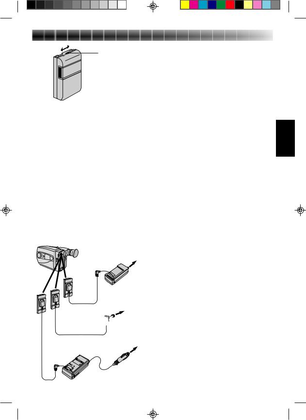
To AC outlet
DC OUT terminal
|
AC Power |
|
DC cord |
Adapter/Charger |
|
AA-V11EG |
||
|
Car Battery Cord  To car’s AP-V7E (optional) cigarette
lighter socket
Car Battery Charger/Adapter
BH-V3E (optional)
USING A CAR BATTERY
Use the optional Car Battery Cord or Car Battery Charger/Adapter (connect as shown in the illustration to the left).
NOTES:
cWhen using the car battery, leave the engine idling.
cThe optional Car Battery Charger (BH-V3E) can also be used to charge the battery pack.
cWhen using the optional Car Battery Charger or Car Battery Cord (AP-V7E), refer to the respective instruction booklet.
USING AC POWER
Use the AC Power Adapter (connect as shown in the illustration to the left).
NOTE:
The supplied AC Power Adapter/Charger features automatic voltage selection in the AC range from 110 V to 240 V.
6


 GETTING
 STARTED
 (cont.)
A
–/+ SET
POWER
Date
Day/Month/Year
DATE ... Date setting is performed
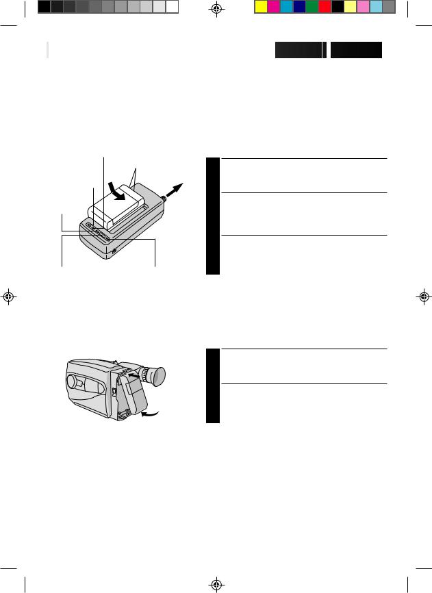
Clock (Lithium) Battery Removal/Insertion
This battery is necessary to operate the clock and to perform date/time settings.
SWITCH OFF POWER
1 Switch off the unit’s power and remove the power supply unit.
OPEN COVER
2 Open the clock battery compartment cover while pressing the release tab.
REMOVE BATTERY (when replacing)
3 Insert a pointed, non-metallic object between the
battery and the compartment ( A ) and pull the battery out.
INSERT BATTERY
4 Ensuring the plus (+) side is up, insert the supplied lithium battery and push it in.
CLOSE COVER
5 Close the compartment cover until it clicks in place.
NOTE:
See “SAFETY PRECAUTIONS”(Z pg. 2) for information on safe handling of lithium batteries.
Date/Time Settings
SELECT MODE
1 Set the power switch to CAMERA.
SET DATE/TIME
2 Press SET and the day blinks. Press + or – to set
the day. Repeat to set month, year, hour and minute.
START CLOCK
3 Press SET. The blinking stops. The date and time are both displayed for confirmation, then the time display disappears.
|
NOTE: |
|
DATE 1.1.00 |
The clock does not keep time while the date and time are |
|
blinking. |
||
TIME 0:00 |
Time
24-hour indication
TIME .... Time setting is performed
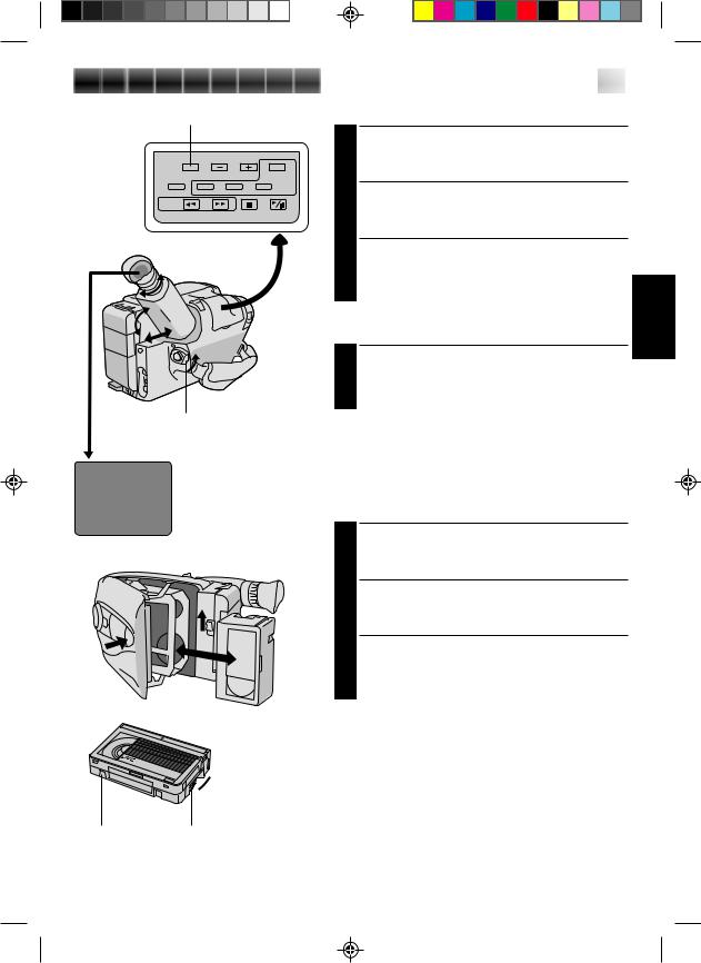
TAPE30•45 tape length select button
|
Set POWER to “CAMERA”. |
|
T30 |
|
Tape length indicator |
|
||


 7
7
Viewfinder Adjustment
POSITION VIEWFINDER
1 Adjust the viewfinder manually for best viewability (see illustration at left).
SELECT MODE
2 Set the power switch to CAMERA.
ADJUST DIOPTER
3 Turn the diopter adjustment control until the indications in the viewfinder are clearly focused.
Tape Length Setting
SET TAPE LENGTH
1 Set the tape length button according to the length of the tape used. T30 = 30 minutes of recording time and T45 = 45 minutes.
NOTE:
The tape remaining time indicator does not work with tapes other than EC30 and EC45. (See Basic Recording on pg. 10 for “tape remaining time indicator”.)
Turn to take up 

 slack.
Erase Protection Gear
Loading/Unloading A Cassette
OPEN CASSETTE HOLDER
1 Slide EJECT until holder opens. Do not use force to open.
INSERT/REMOVE CASSETTE
2 Make sure label is facing outward.
CLOSE CASSETTE HOLDER
3 Press PUSH and make sure the holder is closed and locked.
NOTES:
cA cassette holder can’t be opened unless a power supply is attached.
cMake sure that the tape is not slack when loading the cassette. If there is any slack, turn the gear on the cassette in the direction of the arrow to take up the slack.
cMake sure the Erase Protection tab is present. If not, cover the hole with adhesive tape. (Some cassettes have sliding tabs – in this case, check the tab’s position.)
8


 GETTING
 STARTED
 (cont.)
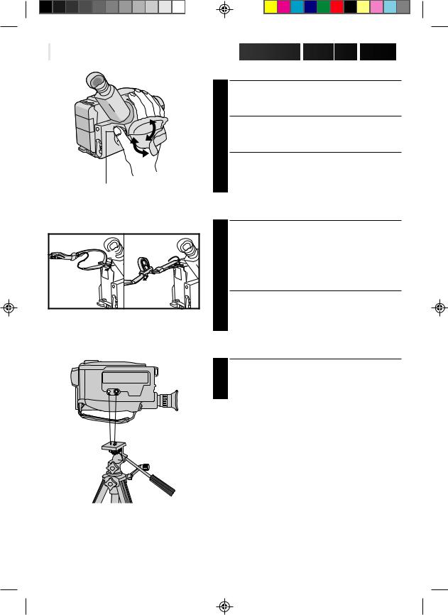
Grip Adjustment
EXPAND LOOP
1 Separate the Velcro strip.
|
INSERT HAND |
|
Pass your right hand through the loop and grasp the |
|
2 grip. |
|
ADJUST STRAP LENGTH |
|
Adjust so your thumb and fingers can easily operate |
Recording Start/Stop button |
3 the Recording Start/Stop button and Power Zoom |
switch. Refasten the Velcro strip. |
|
|
Shoulder Strap Attachment |
|
|
ATTACH STRAP |
|
|
Following the illustration at left, thread the strap |
|
1 |
1 through the top of the eyelet 1, then fold it back |
|
and thread it through the keeper 2, and then |
|
3 |
|
through the buckle 3. Repeat the procedure to |
2 |
2 |
attach the other end of the strap to the other eyelet, |
|
making sure the strap isn’t twisted. |
|
|
1 |
ADJUST LENGTH |
|
|
|
|
|
Adjust as shown in the illustration at left 1, then |
|
|
2 slide both keepers snug against the eyelets to |
|
|
prevent slipping 2. |
Tripod Mounting
ALIGN AND TIGHTEN
1 Align the screw and camera direction stud on the tripod with the camera’s mounting socket and stud hole. Then tighten the screw.
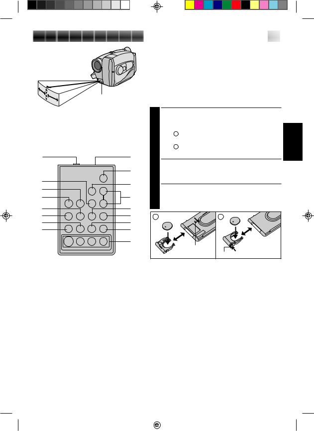
Infrared beam effective area
10°5m
30 |
|
|
|
° |
|
30° |
|
10° |
|||
|
|||
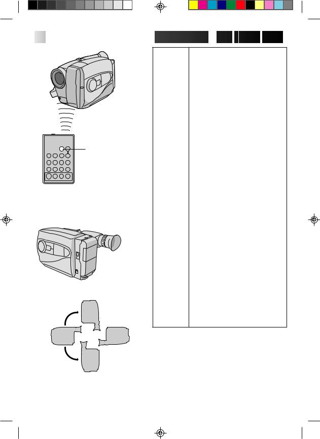
Remote sensor
The transmitted beam may not be effective or may cause misoperations when the remote sensor is directly exposed to sunlight or powerful lighting.
1 |
2 |
|
|
0 |
|
3 |
! |
|
4 |
||
@ |
||
5 |
||
6 |
# |
|
7 |
$ |
|
8 |
% |
|
9 |
^ |
&


 9
9
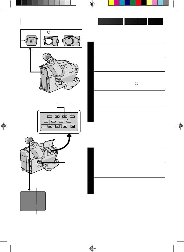
Remote Control Unit
The RM-V704U Full-Function Remote Control Unit can operate this camcorder from a distance as well as the basic operations (PLAY, STOP, PAUSE, FF, and REW) of your VCR. This remote control unit makes additional recording functions possible. To operate, point it at the camcorder’s remote sensor. The RM-V704U is provided with GR-AX460, and is available optionally for GR-AX360/AX260.
PULL OUT BATTERY HOLDER
1 Pull out the battery holder according to the type of remote control unit you have.
Type A : Pull out the battrery holder while sliding the lock hole.
Type B : Pinch the release tab and pull out the battery holder.
INSERT BATTERY
2 Insert the lithium battery* (CR2025), with its plus (+) side up, into the battery holder.
REPLACE BATTERY HOLDER
3 Replace the battery holder until it clicks in place. *Read warning on lithium battery. (Z pg. 2)
A |
B |
|
Lock hole |
|
Release tab |
|
|
|
|
Functions |
|
Buttons |
With the camcorder’s power switch set to |
With the camcorder’s power switch set to |
|||
|
“CAMERA”. |
“PLAY”. |
|||
1PAUSE IN connector |
— |
Z pg. 32 |
|||
2Infrared beam |
Transmits the beam signal. |
|
|||
transmitting window |
|
|
|
|
|
3MBR SET button |
— |
Z pg. 31 |
|||
4INT. TIME button |
Self-Timer/Time lapse (Z pg. 24, 25) |
— |
|||
5REC TIME button |
Animation/Time lapse (Z pg. 25) |
— |
|||
6FF button |
Retake (Forward) (Z pg. 11) |
FF/FF Shuttle Search (Z pg. 28) |
|||
7REW button |
Retake (Rewind) (Z pg. 11) |
Rew/Rew Shuttle Search (Z pg. 28) |
|||
8PAUSE button |
— |
Pause (Z pg. 29) |
|||
9PLAY button |
— |
Playback start (Z pg. 28) |
|||
0START/STOP button |
Functions same as the Recording Start/Stop button of the camcorder. |
||||
!VISS button |
Index code marking (Z pg. 12) |
— |
|||
@ZOOM (T/W) button |
Zoom (invariable speed) (Z pg. 11) |
— |
|||
#VCR CTL button |
— |
Z pg. 31 |
|||
$A. DUB button |
— |
Audio dubbing (Z pg. 35) |
|||
%STOP button |
— |
Stop (Z pg. 28) |
|||
^INSERT button |
— |
Insert Editing (Z pg. 34) |
|||
&R. A. EDIT button |
— |
Z pg. 32 |
|||
|
|
|
|
|
|
|
|
|
|
|
|
|
|
|
|
|
|
|
|
|
|
|
|
10


 RECORDING
 Basic Recording
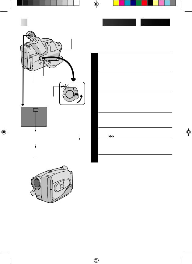
LENS COVER
SWITCH
POWER
Start/Stop
The power indicator
Tape remaining time indicator
45MIN  44MIN
44MIN  3MIN
3MIN
1MIN (Blinking) 2MIN (Blinking)
0MIN (Blinking)
*MIN.....(Now calculating)
NOTE:
You should already have performed the procedures listed below. If not, do so before continuing.
cPower (Z pg. 4)
cTape Length Setting (Z pg. 7)
cGrip Adjustment (Z pg. 8)
LOAD A CASSETTE
1 Slide EJECT to open the cassette holder, then insert the cassette with the label facing out. Press PUSH to ensure the holder is closed and locked.
ENTER RECORD–STANDBY MODE
2 Slide the LENS COVER open/close switch to open the lens cover, then set the power switch to CAMERA.
•The power indicator lights and the camcorder enters the Record–Standby Mode.
•The scene you’re aimed at appears on the viewfinder screen, with the word “PAUSE” superimposed upon it.
START SHOOTING
3 Press the Recording Start/Stop button.
•The tally lamp lights while recording is in progress, and “REC ” appears in the viewfinder.
STOP RECORDING
4 Press the Recording Start/Stop button again.
•The comcorder re-enters the Record-Standby mode.
NOTES:
|
|
c A cassette holder can’t be opened unless a power |
||||
|
|
|
supply is attached. |
|||
|
|
c There may be a delay after you slide EJECT until the |
||||
|
|
|
holder opens. Do not use force. |
|||
|
|
c The tape‘s remaining time is displayed in the |
||||
|
|
|
viewfinder as shown. |
|||
|
|
c “TAPE END” appears when the tape recheas its end, |
||||
|
|
|
and the power goes off automatically if left in this |
|||
|
|
|
condition for 5 minutes. “TAPE END” also appears |
|||
|
|
|
when a cassette whose tape is already at its end is |
|||
|
|
|
loaded. |
|||
Tally lamp |
||||||
c If the Record-Standby mode continues for 5 minutes, |
||||||
|
|
|
the camcorder’s power shuts off automatically. Set the |
|||
|
|
|
power switch to POWER OFF, and then back to |
|||
|
|
|
CAMERA to turn the camcorder on again. |
|||
|
|
c If you’re recording on a cassette from the middle, use |
||||
|
|
|
the RETAKE function (Z pg. 11) to find the end of the |
|||
|
|
|
last recording so you don’t erase any of it. |
|||
|
|
c The LENS COVER warning blinks for about 5 seconds |
||||
|
|
|
when the camcorder is turned on, whether the cover is |
|||
|
|
|
open or closed. |
|||
|
|
|
|
|
|
|
|
|
|
|
|
|
|
|
|
|
|
|
|
|
RECORDING Basic Features
Zoom indicator
Zoom-in
T |
T |
T |
T |
W |
W |
W |
W |
Zoom-out
RETAKE
Power zoom switch
|
11 |
|
FEATURE: |
Zooming |
|
PURPOSE: |
To vary the length of the focal lens and |
|
|
produce zoom in/out effect. |
|
OPERATION: Zoom In
|
1) Pull the power zoom switch down |
|
|
|
toward “T”. |
|
|
|
Zoom Out |
|
|
|
2) Push the switch up toward “W”. |
|
|
NOTES: |
c The further the power zoom switch is |
|
|
|
pushed or pulled, the faster the zoom |
|
|
|
speed becomes. |
|
|
|
c Focusing may become unstable |
|
|
|
during zooming. In this case, set |
|
|
|
zoom while in Record–Standby, set |
|
|
|
manual focus or Focus Lock |
|
|
|
(Z pg. 18, 19), then zoom in or out |
|
|
|
in Record mode. |
|
|
|
|
|
|
FEATURE: |
Quick Review |
|
|
|
|||
PURPOSE: |
To check end of last recording for |
|
|
|
confirmation. |
|
|
OPERATION: 1) Press “ ” for less than 2 seconds during Record–Standby mode.
•Tape is rewound for about 2 seconds and played back automatically, then pauses in Record– Standby mode for next shot.
NOTE: Distortion may occur at start of playback. This is normal.
FEATURE: |
Retake |
|
PURPOSE: |
To re-record certain segments. |
|
OPERATION: |
1) |
Make sure camcorder is in Record– |
|
|
Standby mode. |
|
2) |
Press either RETAKE button to reach |
|
|
start point for new recording. |
|
3) |
Press Recording Start/Stop to start |
|
|
recording. |
NOTE: |
Noise may appear during Retake. This |
|
|
is normal. |
|
12


 RECORDING
 Basic
Basic Features
 (cont.)
 START/STOP
VISS
RM-V704U
(provided with GR-AX460, optional for GR-AX360/AX260)
 AUTO PAUSE
Record-Standby Up
Normal |
Upside down |
FEATURE: |
Index Code Marking |
PURPOSE: |
To give you automatic access to any |
|
selected point on a recording. Auto |
|
Marking and Manual Marking are |
|
available. |
OPERATION: Auto Marking
An index code is always marked to start the first recording on a new date after a cassette is inserted.
Manual Marking
|
1) Press VISS once to place index code. |
|
INDEX blinks in the viewfinder |
|
during marking. |
NOTES: |
c If VISS is pressed during Record– |
|
Standby mode, the mark is placed |
|
where START/STOP is pressed. |
|
c If the date changes during a record- |
|
ing, it becomes the first recording of |
|
the new date and an index mark is |
|
placed at that point. |
|
|
FEATURE: |
AUTO PAUSE SYSTEM (GR-AX460 |
|
only) |
PURPOSE: |
To automatically stop recording when |
|
the camcorder is pointed down, |
|
preventing accidental recordings of the |
|
ground, your feet, etc. |
OPERATION: 1) Set AUTO PAUSE to “ON”. When the camcorder is tilted down by a large degree from its horizontal position during recording, the Record-Standby mode is automatically engaged. “AUTO PAUSE” appears in the viewfinder.
NOTES: c The Auto Pause System is also effective when the camcorder is pointed up, or is positioned upside down.
cAuto Pause also works when the camcorder is twisted by a large degree to the left or right.
cWhen you want to shoot in any of the aforementioned positions, make sure you set AUTO PAUSE to “OFF”.
Record |
Record-Standby |
Record-Standby Down
RECORDING Advanced Features 


 13
13
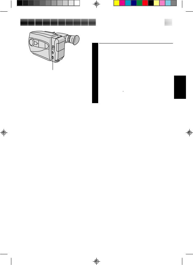
Video Light (GR-AX460 only)
When natural lighting is too dim, you can brighten the scene by using the built-in video light.
SET VIDEO LIGHT |
|
Set the LIGHT ON/AUTO/OFF as required. |
|
1 ON |
: Always keeps the light on as long as the |
|
camcorder is turned on. |
AUTO : Automatically turns on the light when the |
|
|
camcorder senses insufficient lighting on |
LIGHT ON/AUTO/OFF |
the subject. |
OFF |
: Turns off the light. |
•The video light can be used with the camcorder’s power on.
•It is recommended to set the white balance to indoor mode ( ) (Z pg. 15) when you use the video light.
•When not using the video light, turn it off to save battery power.
NOTES:
nEven if the battery indicator ( ) does not blink in the viewfinder, if the battery pack’s charge is low, the camcorder may turn off automatically when you turn on the video light, or when you start recording with the video light turned on.
nWhen the LIGHT ON/AUTO/OFF is set to “AUTO”: •Depending on the lighting condition, the video light
may not be stably turned on or off. In this case, switch the light on and off manually.
•While the Sports or High-Speed Shutter mode
(Z pg. 14) is engaged, the light is likely to stay on. •While the Twilight mode (Z pg. 14) is engaged, the
light will not activate.
DANGER:
nThe video light becomes extremely hot. Do not touch it either while in operation or soon after turning it off, otherwise serious injury may result.
nDo not place the camcorder into the carrying case immediately after using the video light, since it remains extremely hot.
nWhen operating, keep a distance of about
30 cm between the video light and people or object.
nDo not use near flammable or explosive materials.
nIt is recommended that you consult your nearest JVC dealer for replacing the video light.
 Loading...