

Page 1

Illustrated Parts Manual
Model
1850SJ
3121620
March 31, 2014
Page 2

Page 3

REVISION LOG
March 31, 2014 - Original Issue of Manual (Edited to B/M 1001154100 Revision E)
3121620 1850SJ A
Page 4

REVISION LOG
B 1850SJ 3121620
Page 5
GENERAL INFORMATION
Manual # Model Designation PG#
SECTION 6 CYLINDER
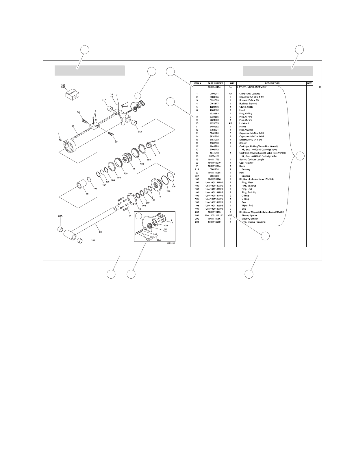
FIGURE 6-3. LIFT CYLINDER ASSEMBLY
PG# Model Designation Manual #
SECTION 6 CYLINDER
FIGURE 6-3. LIFT CYLINDER ASSEMBLY
A
A
1
10
1
2
10
8
7
6
9
2
1) MACHINE IDENTIFICATION
Machines are identified by model & in some cases a combination of model, serial number (SN) or regional standard (i.e.
ANSI CE, CSA). Components may also be identified by SN or manufacturer. Common components that may be identified
by these characteristics are engines & hydraulic components.
2) PARTS MANUAL ORGANIZATION
Product information in this manual is organized under section titles. Frame, Cylinder, Hydraulic & Electrical are a few
examples. Each section is organized by figure & page number. The information within the Figure is then organized by item
number, part number, description & corresponding illustration(s).
3) TABLE OF CONTENTS
A table of contents is found toward the beginning of the manual. Figure number, description & page number are provided for
quick reference to the page containing the related information.
4) RECOMMENDED SPARE PARTS
The Recommended Spare Parts, located near the end of the manual, references most frequently used maintenance parts.
5) PART NUMBER INDEX
A numerical index listing all part numbers & the corresponding page number(s) appears at the back of the manual.
3121620 1850SJ i
Page 6

GENERAL INFORMATION
6) NON-SERVICED PARTS
In some instances, it is necessary to display non-serviced parts, assemblies or installations. In the case of assemblies &
installations there will be a Ref in the Qty column. In the case of parts that are not available for service within assemblies or
components, there will be a NSS (Not Sold Separately) or NLA (No Longer Available) listed in the Qty column of the
manual.
7) PARTS LIST ITEM NUMBERS
Numbers shown in the Item# column correspond to numbers used in the associated illustration(s). Item numbers which are
missing from the sequence in the parts list are not used on that page.
8) INDENTED PART DESCRIPTION
An indented part description is included in the item under which it is indented.
9) ABBREVIATIONS & SYMBOLS
AC.............................................. Alternating Current
ADE............................Advanced Design Electronics
ANSI.............American National Standards Institute
AR.........................................................As Required
ASSY.........................................................Assembly
AUX.............................................................Auxiliary
AWG......................................American Wire Gauge
B/M.....................................................Bill of Material
CE...........................................European Conformity
CCW............................................Counter Clockwise
cm............................................................Centimeter
CW............................................................Clockwise
CSA.......................Canadian Standards Association
CYL..............................................................Cylinder
DIA..............................................................Diameter
DC.......................................................Direct Current
EMS................................................Emergency Stop
ENG...............................................................Engine
FT(ft)..................................................................Feet
GA(Ga)...........................................................Gauge
HYD............................................................Hydraulic
Hz.....................................................................Hertz
ID......................................................Inside Diameter
in.....................................................................inches
ISO............International Organization for Standards
JIC..........................................Joint Industry Council
KG...............................................................Kilogram
L.........................................................................Liter
LB..................................................................Pounds
LCD.........................................Liquid Crystal Display
LED.........................................Light Emitting Diodes
LH..............................................................Left Hand
LSS........................................Load Sensing System
M(m).....................................................Metric/Meter
MM (mm)....................................................Milimeter
mA...............................................................Miliamps
NLA...........................................No Longer Available
NPT........................................National Pipe Threads
NSS...........................................Not Sold Separately
OD.................................................Outside Diameter
ORB......................................................O-Ring Boss
ORFS............................................O-Ring Face Seal
OZ (oz)..........................................................Ounces
PG.....................................................................Page
P/N........................................................Part Number
qt....................................................................Quarts
QTY..............................................................Quantity
REF...........................................................Reference
REV....................................................Revision Level
RH...........................................................Right Hand
SAE.......................Society of Automotive Engineers
SN......................................................Serial Number
SPEC(S).............................................Specifications
T/T..............................................................Turntable
UGM.................................Universal Ground Module
V........................................................................Volts
W......................................................................Watts
#...................................................................Number
10) ILLUSTRATION REFERENCE LETTERS
When necessary, illustrations may contain reference letters that are intended to track information (i. e. hoses, harnesses)
from one point to another or to track visual enlargement of components to show details that may be located in another area
on the illustration.
Note: Due to continuous product improvements, JLG Industries, Inc. reserves the right to make specification changes
without prior notification. Contact JLG Industries, Inc. for updated information.
ii 1850SJ 3121620
Page 7

TABLE OF CONTENTS
FIGURE NO. TITLE PAGE NO.
SECTION 1 - FRAME . . . . . . . . . . . . . . . . . . . . . . . . . . . . . . . . . . . . . . . . . . . . . . . . . . . . . .1-1
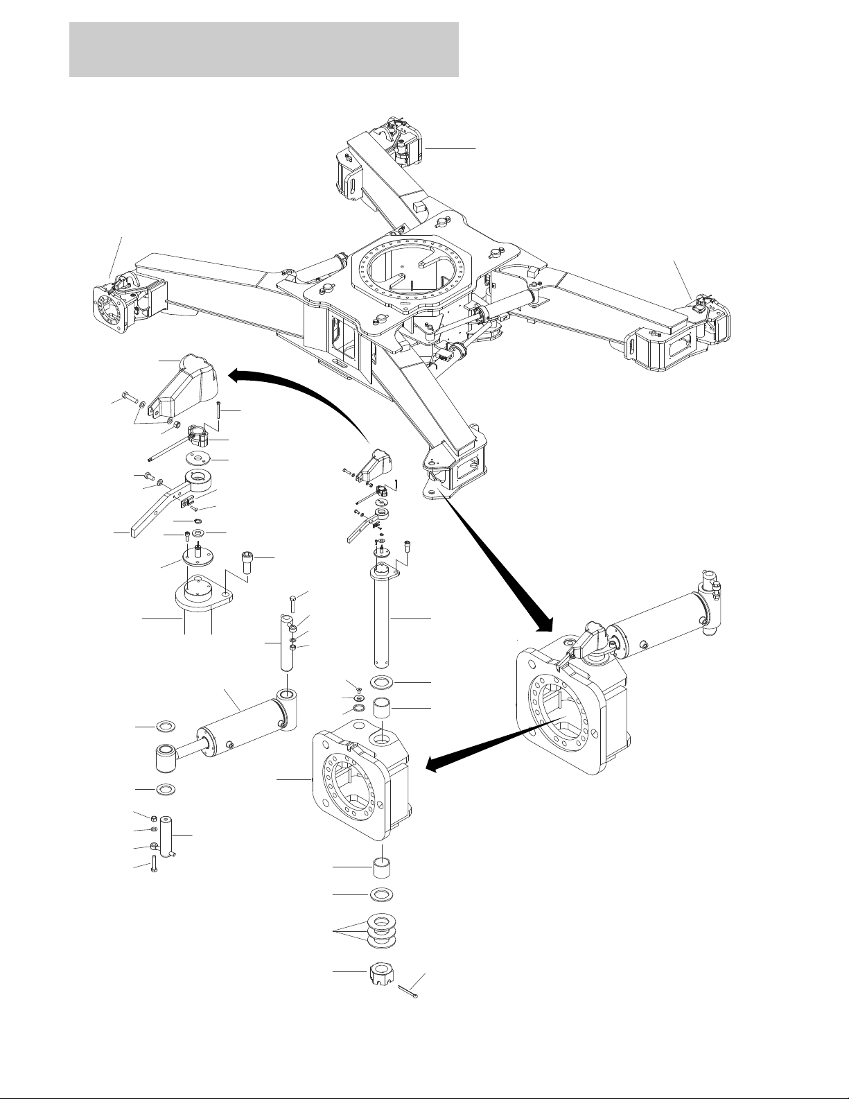
1-1 AXLES INSTALLATION . . . . . . . . . . . . . . . . . . . . . . . . . . . . . . . . . . . . . . . . . . . . . . . . 1-2
1-2 STEERING INSTALLATION . . . . . . . . . . . . . . . . . . . . . . . . . . . . . . . . . . . . . . . . . . . . . 1-4
1-3 WHEEL DRIVE INSTALLATION. . . . . . . . . . . . . . . . . . . . . . . . . . . . . . . . . . . . . . . . . . 1-6
1-4 DRIVE MOTOR ASSEMBLY . . . . . . . . . . . . . . . . . . . . . . . . . . . . . . . . . . . . . . . . . . . . 1-8
1-5 DRIVE HUB ASSEMBLY . . . . . . . . . . . . . . . . . . . . . . . . . . . . . . . . . . . . . . . . . . . . . . 1-10
1-6 TIRE/WHEEL INSTALLATION - IN445/50D710 FOAM-FILLED . . . . . . . . . . . . . . . . . 1-14
1-7 VALVES INSTALLATION - FRAME . . . . . . . . . . . . . . . . . . . . . . . . . . . . . . . . . . . . . . . 1-16
1-8 TRACTION VALVE ASSEMBLY. . . . . . . . . . . . . . . . . . . . . . . . . . . . . . . . . . . . . . . . . . 1-18
1-9 STEER/AXLE EXTEND VALVE ASSEMBLY . . . . . . . . . . . . . . . . . . . . . . . . . . . . . . . . 1-20
1-10 ELECTRICAL COMPONENTS INSTALLATION - FRAME. . . . . . . . . . . . . . . . . . . . . . 1-22
1-11 COVERS INSTALLATION - FRAME . . . . . . . . . . . . . . . . . . . . . . . . . . . . . . . . . . . . . . 1-24
SECTION 2 - TURNTABLE. . . . . . . . . . . . . . . . . . . . . . . . . . . . . . . . . . . . . . . . . . . . . . . . . .2-1
2-1 VALVES & HYDRAULIC FILTERS INSTALLATION - TURNTABLE . . . . . . . . . . . . . . 2-2
2-2 MAIN VALVE ASSEMBLY . . . . . . . . . . . . . . . . . . . . . . . . . . . . . . . . . . . . . . . . . . . . . . 2-4
2-3 TURNTABLE BEARING INSTALLATION. . . . . . . . . . . . . . . . . . . . . . . . . . . . . . . . . . . 2-8
2-4 TURNTABLE LOCK INSTALLATION . . . . . . . . . . . . . . . . . . . . . . . . . . . . . . . . . . . . . . 2-10
2-5 SWING DRIVE INSTALLATION . . . . . . . . . . . . . . . . . . . . . . . . . . . . . . . . . . . . . . . . . . 2-12
2-6 SWING HUB/BRAKE/ Motor ASSEMBLY . . . . . . . . . . . . . . . . . . . . . . . . . . . . . . . . . . 2-14
2-7 COUPLING/COLLECTOR RING INSTALLATION . . . . . . . . . . . . . . . . . . . . . . . . . . . . 2-18
2-8 TANKS INSTALLATION . . . . . . . . . . . . . . . . . . . . . . . . . . . . . . . . . . . . . . . . . . . . . . . . 2-20
2-9 HYDRAULIC TANK ASSEMBLY . . . . . . . . . . . . . . . . . . . . . . . . . . . . . . . . . . . . . . . . . 2-22
2-10 AUXILIARY POWER/BATTERIES INSTALLATIONS. . . . . . . . . . . . . . . . . . . . . . . . . . 2-24
2-11 AUXILIARY PUMP AND MOTOR ASSEMBLY . . . . . . . . . . . . . . . . . . . . . . . . . . . . . . 2-26
2-12 TURNTABLE ELECTRICAL COMPONENTS INSTALLATION . . . . . . . . . . . . . . . . . . 2-28
2-13 GROUND CONTROL CONSOLE ASSEMBLY . . . . . . . . . . . . . . . . . . . . . . . . . . . . . . 2-32
2-14 KEY SWITCH - ANSI, ANSI EXPORT, AUSTRALIAN AND CSA SPECs . . . . . . . . . . 2-34
2-15 KEY SWITCH - CE SPECs. . . . . . . . . . . . . . . . . . . . . . . . . . . . . . . . . . . . . . . . . . . . . . 2-36
2-16 LIGHT PANEL - ANSI, ANSI EXPORT, CSA AND JAPANESE SPECS . . . . . . . . . . . 2-38
2-17 LIGHT PANEL - AUSTRALIAN & CE SPECS . . . . . . . . . . . . . . . . . . . . . . . . . . . . . . . 2-40
2-18 ELECTRICAL PANEL ASSEMBLY. . . . . . . . . . . . . . . . . . . . . . . . . . . . . . . . . . . . . . . . 2-42
2-19 ALARM INSTALLATION . . . . . . . . . . . . . . . . . . . . . . . . . . . . . . . . . . . . . . . . . . . . . . . . 2-44
2-20 BEACON LIGHT INSTALLATION - OPTIONAL . . . . . . . . . . . . . . . . . . . . . . . . . . . . . . 2-46
2-21 HOOD INSTALLATION . . . . . . . . . . . . . . . . . . . . . . . . . . . . . . . . . . . . . . . . . . . . . . . 2-48
2-22 VENTURI INSTALLATION . . . . . . . . . . . . . . . . . . . . . . . . . . . . . . . . . . . . . . . . . . . . 2-54
SECTION 3 - ENGINE . . . . . . . . . . . . . . . . . . . . . . . . . . . . . . . . . . . . . . . . . . . . . . . . . . . . .3-1
3-1 DEUTZ LRC ENGINE INSTALLATION - NO COLD WEATHER PKG . . . . . . . . . . . . . 3-2
3-2 DEUTZ LRC ENGINE/PUMP ASSEMBLY - NO COLD WEATHER PKG . . . . . . . . . . 3-6
3-3 DEUTZ LRC ENGINE ASSEMBLY - NO COLD WEATHER PKG . . . . . . . . . . . . . . . . 3-8
3-4 DEUTZ LRC ENGINE INSTALLATION - WITH COLD WEATHER PKG . . . . . . . . . . . 3-14
3-5 DEUTZ LRC ENGINE/PUMP ASSEMBLY - WITH COLD WEATHER PKG . . . . . . . . 3-18
3-6 DEUTZ LRC ENGINE ASSEMBLY - WITH COLD WEATHER PKG . . . . . . . . . . . . . . 3-20
3-7 DEUTZ LRC ENGINE COMPONENTS . . . . . . . . . . . . . . . . . . . . . . . . . . . . . . . . . . . 3-26
3-8 DEUTZ T4i ENGINE INSTALLATION - NO COLD WEATHER PKG . . . . . . . . . . . . . . 3-30
3-9 DEUTZ T4i ENGINE/PUMP ASSEMBLY - NO COLD WEATHER PKG . . . . . . . . . . . 3-34
3-10 DEUTZ T4i ENGINE ASSEMBLY - NO COLD WEATHER PKG . . . . . . . . . . . . . . . . . 3-36
3-11 DEUTZ T4i ENGINE INSTALLATION - WITH COLD WEATHER PKG . . . . . . . . . . . . 3-42
3-12 DEUTZ T4i ENGINE/PUMP ASSEMBLY - WITH COLD WEATHER PKG . . . . . . . . . 3-46
3-13 DEUTZ T4i ENGINE ASSEMBLY - WITH COLD WEATHER PKG . . . . . . . . . . . . . . . 3-48
3121620 1850SJ i
Page 8

TABLE OF CONTENTS
FIGURE NO. TITLE PAGE NO.
3-14 DEUTZ T4i ENGINE COMPONENTS . . . . . . . . . . . . . . . . . . . . . . . . . . . . . . . . . . . .3-54
3-15 PUMP COUPLING KIT . . . . . . . . . . . . . . . . . . . . . . . . . . . . . . . . . . . . . . . . . . . . . . . . .3-60
3-16 TANDEM PUMP ASSEMBLY . . . . . . . . . . . . . . . . . . . . . . . . . . . . . . . . . . . . . . . . . . . .3-62
3-17 PISTON PUMP ASSEMBLY . . . . . . . . . . . . . . . . . . . . . . . . . . . . . . . . . . . . . . . . . . . .3-66
3-18 GEAR PUMP ASSEMBLY . . . . . . . . . . . . . . . . . . . . . . . . . . . . . . . . . . . . . . . . . . . . . .3-70
3-19 SPARK ARRESTOR INSTALLATION - DEUTZ LRC (OPTIONAL) . . . . . . . . . . . . . .3-72
3-20 SPARK ARRESTOR INSTALLATION - DEUTZ T4i (OPTIONAL) . . . . . . . . . . . . . . .3-74
SECTION 4 - BOOM. . . . . . . . . . . . . . . . . . . . . . . . . . . . . . . . . . . . . . . . . . . . . . . . . . . . . . .4-1
4-1 BOOM INSTALLATION . . . . . . . . . . . . . . . . . . . . . . . . . . . . . . . . . . . . . . . . . . . . . . . . .4-2
4-2 BOOM ASSEMBLY . . . . . . . . . . . . . . . . . . . . . . . . . . . . . . . . . . . . . . . . . . . . . . . . . . . .4-4
4-3 JIB INSTALLATION . . . . . . . . . . . . . . . . . . . . . . . . . . . . . . . . . . . . . . . . . . . . . . . . . . . .4-12
4-4 JIB ASSEMBLY . . . . . . . . . . . . . . . . . . . . . . . . . . . . . . . . . . . . . . . . . . . . . . . . . . . . . . .4-16
4-5 PLATFORM ROTATOR ASSEMBLY . . . . . . . . . . . . . . . . . . . . . . . . . . . . . . . . . . . . . .4-18
4-6 JIB ROTATOR ASSEMBLY . . . . . . . . . . . . . . . . . . . . . . . . . . . . . . . . . . . . . . . . . . . . .4-20
4-7 PLATFORM SUPPORT INSTALLATION - NO LSS . . . . . . . . . . . . . . . . . . . . . . . . . .4-22
4-8 PLATFORM SUPPORT INSTALLATION - WITH LSS . . . . . . . . . . . . . . . . . . . . . . . .4-24
4-9 POWER TRACK INSTALLATION - BOOM . . . . . . . . . . . . . . . . . . . . . . . . . . . . . . . . . .4-26
4-10 VALVES INSTALLATION - BOOM . . . . . . . . . . . . . . . . . . . . . . . . . . . . . . . . . . . . . . . .4-30
4-11 JIB VALVE ASSEMBLY . . . . . . . . . . . . . . . . . . . . . . . . . . . . . . . . . . . . . . . . . . . . . . . .4-32
4-12 PLATFORM VALVE ASSEMBLY . . . . . . . . . . . . . . . . . . . . . . . . . . . . . . . . . . . . . . . . .4-36
4-13 BOOM SENSORS AND SWITCHES INSTALLATION . . . . . . . . . . . . . . . . . . . . . . . . .4-38
4-14 BOOM CABLES - ANSI, ANSI EXPORT, CSA AND JAPANESE SPECS . . . . . . . . . .4-44
4-15 Boom CABLES (AUSTRALIAN AND CE SPECS) . . . . . . . . . . . . . . . . . . . . . . . . . . . .4-46
4-16 BOOM CABLES - SKYPOWER . . . . . . . . . . . . . . . . . . . . . . . . . . . . . . . . . . . . . . . . . .4-48
4-17 JIB ENCLOSURE BOX ASSEMBLY . . . . . . . . . . . . . . . . . . . . . . . . . . . . . . . . . . . . . . .4-50
SECTION 5 - PLATFORM. . . . . . . . . . . . . . . . . . . . . . . . . . . . . . . . . . . . . . . . . . . . . . . . . .5-1
5-1 PLATFORM ASSEMBLY - SIDE GATE ENTRY . . . . . . . . . . . . . . . . . . . . . . . . . . . . . .5-2
5-2 PLATFORM ASSEMBLY - DROP BAR ENTRY . . . . . . . . . . . . . . . . . . . . . . . . . . . . . .5-4
5-3 PLATFORM ASSEMBLY - FALL ARREST - ANSI SPEC . . . . . . . . . . . . . . . . . . . . . . .5-6
5-4 PLATFORM ASSEMBLY - FALL ARREST - AUSTRALIAN AND CE SPECS . . . . . . .5-8
5-5 TRAY INSTALLATION . . . . . . . . . . . . . . . . . . . . . . . . . . . . . . . . . . . . . . . . . . . . . . . . .5-10
5-6 LCD DISPLAY INSTALLATION. . . . . . . . . . . . . . . . . . . . . . . . . . . . . . . . . . . . . . . . . . .5-12
5-7 PLATFORM CONTROLS INSTALLATION . . . . . . . . . . . . . . . . . . . . . . . . . . . . . . . . . .5-14
5-8 PLATFORM CONSOLE ASSEMBLY . . . . . . . . . . . . . . . . . . . . . . . . . . . . . . . . . . . . . .5-16
5-9 DECAL AND LIGHT PANEL - ANSI, ANSI EXPORT, CSA AND JAPANESE SPECS .5-20
5-10 DECAL AND LIGHT PANEL - AUSTRALIAN AND CE SPECS . . . . . . . . . . . . . . . . . .5-22
5-11 LIFT AND SWING CONTROLLER ASSEMBLY . . . . . . . . . . . . . . . . . . . . . . . . . . . . . .5-24
5-12 DRIVE AND STEER CONTROLLER ASSEMBLY . . . . . . . . . . . . . . . . . . . . . . . . . . . .5-26
5-13 FOOTSWITCH ASSEMBLY . . . . . . . . . . . . . . . . . . . . . . . . . . . . . . . . . . . . . . . . . . . . .5-28
SECTION 6 - CYLINDER . . . . . . . . . . . . . . . . . . . . . . . . . . . . . . . . . . . . . . . . . . . . . . . . . . . 6-1
6-1 AXLE EXTEND CYLINDER ASSEMBLY . . . . . . . . . . . . . . . . . . . . . . . . . . . . . . . . . . .6-2
6-2 BOOM LIFT CYLINDER ASSEMBLY . . . . . . . . . . . . . . . . . . . . . . . . . . . . . . . . . . . .6-4
6-3 BOOM TELESCOPE CYLINDER ASSEMBLY . . . . . . . . . . . . . . . . . . . . . . . . . . . . . .6-6
6-4 JIB LEVEL (SLAVE) CYLINDER ASSEMBLY. . . . . . . . . . . . . . . . . . . . . . . . . . . . . . . .6-8
6-5 JIB LIFT CYLINDER ASSEMBLY . . . . . . . . . . . . . . . . . . . . . . . . . . . . . . . . . . . . . . . . .6-10
6-6 JIB LOCK CYLINDER ASSEMBLY . . . . . . . . . . . . . . . . . . . . . . . . . . . . . . . . . . . . . . . .6-12
6-7 JIB TELESCOPE CYLINDER ASSEMBLY . . . . . . . . . . . . . . . . . . . . . . . . . . . . . . . .6-14
6-8 PLATFORM LEVEL (SLAVE) CYLINDER ASSEMBLY . . . . . . . . . . . . . . . . . . . . . . .6-16
ii 1850SJ 3121620
Page 9

TABLE OF CONTENTS
FIGURE NO. TITLE PAGE NO.
6-9 STEER CYLINDER ASSEMBLY . . . . . . . . . . . . . . . . . . . . . . . . . . . . . . . . . . . . . . . . . 6-18
SECTION 7 - HYDRAULICS . . . . . . . . . . . . . . . . . . . . . . . . . . . . . . . . . . . . . . . . . . . . . . . . .7-1
7-1 BOOM AND JIB HYDRAULIC DIAGRAM. . . . . . . . . . . . . . . . . . . . . . . . . . . . . . . . . . . 7-2
7-2 CHASSIS HYDRAULIC DIAGRAM. . . . . . . . . . . . . . . . . . . . . . . . . . . . . . . . . . . . . . . . 7-4
7-3 TURNTABLE HYDRAULIC DIAGRAM . . . . . . . . . . . . . . . . . . . . . . . . . . . . . . . . . . . . . 7-8
7-4 HYDRAULIC DIAGRAM LIST . . . . . . . . . . . . . . . . . . . . . . . . . . . . . . . . . . . . . . . . . . . 7-12
SECTION 8 - ELECTRICAL . . . . . . . . . . . . . . . . . . . . . . . . . . . . . . . . . . . . . . . . . . . . . . . . .8-1
8-1 ELECTRICAL DIAGRAM LIST . . . . . . . . . . . . . . . . . . . . . . . . . . . . . . . . . . . . . . . . . . . 8-2
8-2 AXLE SENSOR HARNESS AND COMPONENTS . . . . . . . . . . . . . . . . . . . . . . . . . . . 8-4
8-3 CHASSIS HARNESS . . . . . . . . . . . . . . . . . . . . . . . . . . . . . . . . . . . . . . . . . . . . . . . . . . 8-6
8-4 COUPLING/COLLECTOR RING HARNESS & COMPONENTS . . . . . . . . . . . . . . . . . 8-12
8-5 DRIVE PUMP HARNESS . . . . . . . . . . . . . . . . . . . . . . . . . . . . . . . . . . . . . . . . . . . . . . 8-14
8-6 TURNTABLE HARNESS . . . . . . . . . . . . . . . . . . . . . . . . . . . . . . . . . . . . . . . . . . . . . . . 8-16
8-7 GROUND CONTROL PANEL HARNESS . . . . . . . . . . . . . . . . . . . . . . . . . . . . . . . . . . 8-26
8-8 VALVE BANK HARNESS . . . . . . . . . . . . . . . . . . . . . . . . . . . . . . . . . . . . . . . . . . . . . . . 8-32
8-9 BLAM HARNESS . . . . . . . . . . . . . . . . . . . . . . . . . . . . . . . . . . . . . . . . . . . . . . . . . . . . . 8-38
8-10 FUEL PUMP & WIF HARNESS . . . . . . . . . . . . . . . . . . . . . . . . . . . . . . . . . . . . . . . . . . 8-42
8-11 BATTERY CABLE KIT . . . . . . . . . . . . . . . . . . . . . . . . . . . . . . . . . . . . . . . . . . . . . . . . . 8-44
8-12 TILT SENSOR HARNESS . . . . . . . . . . . . . . . . . . . . . . . . . . . . . . . . . . . . . . . . . . . . . . 8-46
8-13 MTS CONNECTION CABLE . . . . . . . . . . . . . . . . . . . . . . . . . . . . . . . . . . . . . . . . . . . . 8-48
8-14 LOAD SENSOR CABLE . . . . . . . . . . . . . . . . . . . . . . . . . . . . . . . . . . . . . . . . . . . . . . . . 8-50
8-15 ALARM HARNESS . . . . . . . . . . . . . . . . . . . . . . . . . . . . . . . . . . . . . . . . . . . . . . . . . . . 8-52
8-16 BEACON LIGHT (AMBER) HARNESS . . . . . . . . . . . . . . . . . . . . . . . . . . . . . . . . . . . . 8-54
8-17 ENGINE HARNESS . . . . . . . . . . . . . . . . . . . . . . . . . . . . . . . . . . . . . . . . . . . . . . . . . . . 8-56
8-18 ENGINE CAN HARNESS . . . . . . . . . . . . . . . . . . . . . . . . . . . . . . . . . . . . . . . . . . . . . . 8-62
8-19 PROXIMITY SENSOR HARNESS AND COMPONENTS . . . . . . . . . . . . . . . . . . . . . . 8-64
8-20 PROXIMITY SENSOR HARNESS AND COMPONENTS . . . . . . . . . . . . . . . . . . . . . . 8-66
8-21 ANGLE SENSOR HARNESS AND COMPONENTS . . . . . . . . . . . . . . . . . . . . . . . . . . 8-68
8-22 SENSOR HARNESS AND COMPONENTS . . . . . . . . . . . . . . . . . . . . . . . . . . . . . . . . 8-70
8-23 BOOM LENGTH SENSOR HARNESS AND COMPONENTS . . . . . . . . . . . . . . . . . . 8-72
8-24 BOOM SENSOR HARNESS . . . . . . . . . . . . . . . . . . . . . . . . . . . . . . . . . . . . . . . . . . . . 8-74
8-25 BOOM HARNESS . . . . . . . . . . . . . . . . . . . . . . . . . . . . . . . . . . . . . . . . . . . . . . . . . . . . 8-76
8-26 TRANSPORT SWITCH HARNESS . . . . . . . . . . . . . . . . . . . . . . . . . . . . . . . . . . . . . . 8-78
8-27 PLATFORM VALVE HARNESS . . . . . . . . . . . . . . . . . . . . . . . . . . . . . . . . . . . . . . . . . 8-80
8-28 MAIN BOOM CONTROL CABLE . . . . . . . . . . . . . . . . . . . . . . . . . . . . . . . . . . . . . . . . . 8-84
8-29 JIB CONTROL CABLE . . . . . . . . . . . . . . . . . . . . . . . . . . . . . . . . . . . . . . . . . . . . . . . . 8-86
8-30 MAIN BOOM 16/4 CABLE . . . . . . . . . . . . . . . . . . . . . . . . . . . . . . . . . . . . . . . . . . . . . . 8-88
8-31 BOOM AC CABLE - ANSI, ANSI EXPORT, CSA AND JAPANESE SPECS . . . . . . . 8-90
8-32 BOOM AC CABLE - AUSTRALIAN & CE SPECS . . . . . . . . . . . . . . . . . . . . . . . . . . . . 8-92
8-33 JIB AC CABLE - ANSI, ANSI EXPORT, CSA AND JAPANESE SPECS . . . . . . . . . . 8-94
8-34 JIB AC CABLE - AUSTRALIAN AND CE SPECS . . . . . . . . . . . . . . . . . . . . . . . . . . . . 8-96
8-35 BOOM AC CABLE - SKYPOWER . . . . . . . . . . . . . . . . . . . . . . . . . . . . . . . . . . . . . . . . 8-98
8-36 JIB AC CABLE - SKYPOWER . . . . . . . . . . . . . . . . . . . . . . . . . . . . . . . . . . . . . . . . . . . 8-100
8-37 JIB VALVE HARNESS . . . . . . . . . . . . . . . . . . . . . . . . . . . . . . . . . . . . . . . . . . . . . . . . . 8-102
8-38 LCD DISPLAY HARNESS . . . . . . . . . . . . . . . . . . . . . . . . . . . . . . . . . . . . . . . . . . . . . . 8-108
8-39 PLATFORM CONSOLE Harness . . . . . . . . . . . . . . . . . . . . . . . . . . . . . . . . . . . . . . . . 8-110
8-40 RECEPTACLE & CLAMP INSTALLATION - SUPPLIED LOCALLY . . . . . . . . . . . . . 8-120
8-41 RECEPTACLE & CLAMP INSTALLATION - 110V - ANSI SPEC . . . . . . . . . . . . . . . . 8-122
8-42 RECEPTACLE & CLAMP INSTALLATION - 220V - ANSI SPEC . . . . . . . . . . . . . . . . 8-124
3121620 1850SJ iii
Page 10

TABLE OF CONTENTS
FIGURE NO. TITLE PAGE NO.
8-43 BREAKER BOX ASSEMBLY - CE SPEC . . . . . . . . . . . . . . . . . . . . . . . . . . . . . . . . . .8-126
8-44 KIT - BREAKER BOX . . . . . . . . . . . . . . . . . . . . . . . . . . . . . . . . . . . . . . . . . . . . . . . . .8-128
SECTION 9 - DECALS . . . . . . . . . . . . . . . . . . . . . . . . . . . . . . . . . . . . . . . . . . . . . . . . . . . . .9-1
9-1 DECAL INSTALLATION - ANSI SPEC . . . . . . . . . . . . . . . . . . . . . . . . . . . . . . . . . . . . .9-2
9-2 DECAL INSTALLATION - ANSI EXPORT SPEC . . . . . . . . . . . . . . . . . . . . . . . . . . . . .9-6
9-3 DECAL INSTALLATION - AUSTRALIAN SPEC . . . . . . . . . . . . . . . . . . . . . . . . . . . . . .9-10
9-4 DECAL INSTALLATION - BRAZIL SPEC . . . . . . . . . . . . . . . . . . . . . . . . . . . . . . . . . . .9-12
9-5 DECAL INSTALLATION - CE SPEC . . . . . . . . . . . . . . . . . . . . . . . . . . . . . . . . . . . . . . .9-16
9-6 DECAL INSTALLATION - CHINESE SPEC . . . . . . . . . . . . . . . . . . . . . . . . . . . . . . . . .9-18
9-7 DECAL INSTALLATION - CSA SPEC. . . . . . . . . . . . . . . . . . . . . . . . . . . . . . . . . . . . . .9-22
9-8 DECAL INSTALLATION - JAPANESE SPEC . . . . . . . . . . . . . . . . . . . . . . . . . . . . . . . .9-26
9-9 DECAL INSTALLATION - KOREAN SPEC . . . . . . . . . . . . . . . . . . . . . . . . . . . . . . . . . .9-30
9-10 DECAL INSTALLATION - OPTIONS. . . . . . . . . . . . . . . . . . . . . . . . . . . . . . . . . . . . . . .9-34
SECTION 10 - RECOMMENDED SERVICE PARTS STOCK. . . . . . . . . . . . . . . . . . . . . . . .9-1
SECTION 11 - SPECIAL OPTIONS . . . . . . . . . . . . . . . . . . . . . . . . . . . . . . . . . . . . . . . . . . . 10-1
SECTION 12 - PART NUMBER INDEX . . . . . . . . . . . . . . . . . . . . . . . . . . . . . . . . . . . . . . . .11-1
iv 1850SJ 3121620
Page 11

SECTION 1
FRAME
3121620 1850SJ 1-1
Page 12

SECTION 1 FRAME
1001156464
5
1
13
26
20
12
12
9
4
4
8
8
14
10
10
15
23
23
25
1
25
1
24
17
7
2
6
11
3
16
19
18
22
21
FIGURE 1-1. AXLES INSTALLATION
1-2 1850SJ 3121620
Page 13

SECTION 1 FRAME
FIGURE 1-1. AXLES INSTALLATION
ITEM # PART NUMBER QTY. DESCRIPTION REV.
1001156464 Ref AXLES INSTALLATION D
1 0100011 AR Compound, Locking
2 0100071 AR Compound, Locking
3 0440273 8 Bushing
4 0701420001 8 Bolt M14 x 60
5 0761015001 8 Bolt M10 x 35
6 0762418001 8 Bolt M24 x 50
7 3020039 AR Lubricant
8 3291407001 8 Nut M14
9 3422912 4 Pin
10 3841258 8 Keeper, Pin
11 3841356 4 Keeper, Pin
12 4740229 8 Washer, Thrust
13 1001172358 8 Washer M10
14 4812200001 8 Washer M14
15 1001120000 4 Pin
16 1001155133 4 Washer, Thrust
17 1001155363 4 Pin
18 1001155619 1 Axle - Front RH
19 1001155690 1 Axle - Front LH
20 1001156648 4 Axle Extend Cylinder Assembly (See CYLINDER SECTION for
Breakdown)
21 1001156862 1 Axle - Rear RH
22 1001156863 1 Axle - Rear LH
23 1001157007 8 Sleeve
24 1001157084 4 Sensor Assembly (See ELECTRICAL SECTION for Breakdown)
25 1001157466 8 Bolt M10 x 30
26 1001158017 AR Shim
3121620 1850SJ 1-3
Page 14
SECTION 1 FRAME
6
11
26
9
2
20
1
29
1
5
8
1726252424
12
1
14
7
7
36361031911832128353430
22
31
4
131627
382713
23
23
16
4
37
33
33
32
32
1001156606
FIGURE 1-2. STEERING INSTALLATION
1-4 1850SJ 3121620
Page 15

SECTION 1 FRAME
FIGURE 1-2. STEERING INSTALLATION
ITEM # PART NUMBER QTY. DESCRIPTION REV.
1001156606 Ref STEERING INSTALLATION D
1 0100011 AR Compound, Locking
2 0100019 AR Compound, Locking
3 0100035 AR Compound, Locking
4 0701422001 8 Bolt M14 x 70
5 0760808001 4 Bolt M8 x 16
6 0760815001 4 Bolt M8 x 35
7 0962423 8 Bushing
8 1120549 4 Cap
9 1671040 4 Cover
10 2080091 4 Screw M4 x 16
11 3290805001 4 Nut M8
12 3300464001 4 Nut
13 3291214001 8 Nut M14
14 3451214 4 Pin, Cotter
15 3760383 4 Ring
16 3841258 8 Keeper, Pin
17 3960551 4 Seal
18 4031512 8 Capscrew M4 x 40
19 4031707 16 Capscrew M6 x 16
20 4032311001 8 Capscrew M16 x 35
21 4460914 4 Base, Terminal
22 4711800 4 Washer 1/2
23 4740229 8 Washer, Thrust
24 4740505 8 Washer, Thrust
25 4755000001 AR Washer 2-1/2
26 4811900001 12 Washer M8
27 4812200001 8 Washer M14
28 1001146963 4 Sensor Assembly (See ELECTRICAL SECTION for Breakdown)
29 1001174345 4 Screw M20 x 20
30 1001155836 4 Adapter
31 1001155986 4 Steer Cylinder Assembly (See CYLINDER SECTION for
Breakdown)
32 1001156678 2 Spindle - Front LH & Rear RH
33 1001156679 2 Spindle - Front RH & Rear LH
34 1001156778 4 Pin
35 1001156785 4 Link
36 1001156815 4 Kingpin
37 1001156991 4 Pin
38 1001156996 4 Pin
39 1001155817 4 Harness, Steer (See ELECTRICAL SECTION for Breakdown)
3121620 1850SJ 1-5
Page 16

SECTION 1 FRAME
1
2
201
202
3
5
5
5
4
4
4
206
207
205
204
101
105
106
104
103
102
1001157850
FIGURE 1-3. WHEEL DRIVE INSTALLATION
1-6 1850SJ 3121620
Page 17

SECTION 1 FRAME
FIGURE 1-3. WHEEL DRIVE INSTALLATION
ITEM # PART NUMBER QTY. DESCRIPTION REV.
1001157850 Ref WHEEL DRIVE INSTALLATION D
1 0100019 AR Compound, Locking
2 0762018001 64 Bolt M20 x 50
3 5242000001 64 Washer M20
4 1001154759 2 Drive Hub/Motor with Fittings - Front LH & Rear RH (See Items
101-106 for Breakdown)
5 1001157849 2 Drive Hub/Motor with Fittings - Front RH & Rear LH (See Items
101-106 for Breakdown)
1001154759 Ref HUB/MOTOR ASSEMBLY WITH FITTINGS - FRONT LH & REAR
RH
1001157849 Ref HUB/MOTOR ASSEMBLY WITH FITTINGS - FRONT RH & REAR
LH
101 2110808 1 Fitting, Straight ORFS/ORB
102 2220415 1 Fitting, Straight JIC/ORB
103 2220472 1 Fitting, 90 JIC/ORB
104 2111012 1 Fitting, Straight ORFS/ORB
104 2131012 1 Fitting, 90 ORFS/ORB
105 2111012 1 Fitting, Straight ORFS/ORB
105 2131012 1 Fitting, 90 ORFS/ORB
106 1001154772 1 Drive Hub/Motor (See Items 201-207 for Breakdown)
1001154772 Ref DRIVE HUB/MOTOR ASSEMBLY B
201 0100011 AR Compound, Locking
202 0761214 2 Bolt M12 x 30
203 3020008 2.6qt/2.5L Lube, Gear (Not Shown)
204 3160339 1 Motor - Drive (See DRIVE MOTOR ASSEMBLY for Breakdown)
205 3790158 1 O-Ring
206 5241200 2 Washer M12
207 1001149921 1 Hub - Drive (See DRIVE HUB ASSEMBLY for Breakdown)
D
D
3121620 1850SJ 1-7
Page 18

SECTION 1 FRAME
1
2
3
3
4
5
6
7
8
9
10
11
12
13
14
15
16
17
20
21
18
19
22
23
24
25
26
27
28
29
30
31
32
33
34
35
36
34
51
52
3160339
FIGURE 1-4. DRIVE MOTOR ASSEMBLY
1-8 1850SJ 3121620
Page 19

SECTION 1 FRAME
FIGURE 1-4. DRIVE MOTOR ASSEMBLY
ITEM # PART NUMBER QTY. DESCRIPTION REV.
3160339 Ref DRIVE MOTOR ASSEMBLY B
1 7022368 4 Bolt
2 70000859 1 End Cap, Motor
3 70003628 2 Locating Pin
4 See Note 1 O-Ring (Note: Use p/n 70000862)
5 7007420 1 Plug (Includes Item 4)
6 7007446 1 Pin, Dowel
7 7021249 1 Bearing, Needle
8 70000854 1 Plate, Valve
9 7022311 1 Snap Ring
10 7022314 1 Retainer, Spring
11 7024867 1 Spring
12 7024868 1 Washer (was p/n 7022313)
13 70000855 1 Block, Cylinder
14 7021275 3 Pin, Slipper
15 70000856 1 Guide
16 70000857 1 Retainer, Slipper
17 7024865 9 Piston, Cylinder
18 See Note 1 Ring, Piston (Note: Use p/n 70000862)
19 See Note 1 O-Ring (Note: Use p/n 70000862)
20 70000860 1 Piston, Servo (Includes Items 18 & 19)
21 70000861 1 Spring
22 See Note 1 Pin (Note: Not Available for Purchase)
23 70000853 1 Swashplate
24 70000852 1 Kit, Bearing
25 See Note 1 Gasket (Note: Use p/n 70000862)
26 See Note 1 Plug (Note: Not Available for Purchase)
27 See Note 1 O-Ring (Note: Use p/n 70000862)
28 7022321 1 Plug (Includes Item 29)
29 See Note 1 O-Ring (Note: Use p/n 70000862)
30 See Note 1 Housing (Note: Not Available - Purchase Complete Motor)
31 70000858 1 Shaft
32 7007437 1 Bearing
33 7007439 1 Snap Ring
34 7007438 2 Snap Ring
35 See Note 1 Seal (Note: Use p/n 70000862)
36 7022371 1 Washer, Seal Support
51 70000862 1 Kit, Motor Seal (Includes Items 4,18,19,25,27,29 & 35)
52 7027740 1 Kit, Cylinder Block (Includes Items 9 - 17)
3121620 1850SJ 1-9
Page 20

SECTION 1 FRAME
46
45
37
36
343530
29
27
28
17
16
1514131211181087619432
5
19
20
21
24
23
22
26
313233
33
25
42
39
39
41
40
38
49
55
545352
50
51
47
48
49
48
56
43
44
101
102
100
1001149921
FIGURE 1-5. DRIVE HUB ASSEMBLY
1-10 1850SJ 3121620
Page 21

SECTION 1 FRAME
FIGURE 1-5. DRIVE HUB ASSEMBLY
ITEM # PART NUMBER QTY. DESCRIPTION REV.
1001149921 Ref DRIVE HUB ASSEMBLY F
1 70004429 1 Ring
2 See Note 2 Screw M6x20 (Note: Use p/n 70004452)
3 See Note 1 Cover (Note: Use p/n 70004452)
4 See Note 1 Gasket (Note: Use p/n 70004452 or 70004451)
5 See Note 2 Plug (Includes O-Ring) (Note: Use p/n 70004452)
6 See Note 1 Cover (Note: Use p/n 70004452)
7 See Note 1 O-Ring (Note: Use p/n 70004452 or 70004451)
8 See Note 1 Shim (Note: Use p/n 70004452)
9 See Note 1 Pin (Note: Use p/n 70004452)
10 See Note 1 O-Ring (Note: Use p/n 70004452 or 70004451)
11 70004430 1 Pinion
12 70004431 1 Ring, Retaining
13 70004432 1 Assembly, Gear Reduction
14 70004433 1 Pinion
15 70004434 1 Ring
16 70004435 1 Assembly, Gear Reduction
17 70004436 1 Pinion
18 NSS Housing, Hub
19 70002052 2 Screw M10 x 25
20 70004437 6 Screw M6 x 14
21 70004437 1 Plug
22 70002032 4 Ring, Retaining
23 70002031 4 Bearing
24 70004439 4 Wheel, Planet
25 70004440 1 Flange
26 See Note 1 O-Ring (Note: Use p/n 70004451)
27 70004441 1 Nut
28 70004363 2 Screw M6 x 10
29 70004442 1 Bearing
30 NSS Support, Hub
31 See Note 1 O-Ring (Note: Use p/n 70004451)
32 70004443 1 Bearing
33 See Note 1 Seal (Note: Use p/n 70004451)
34 70004444 1 Coupling
35 70002036 1 Spring
36 70004445 1 Ring, Retaining
37 70004446 1 Bearing
38 NSS Axle
39 70004447 3 Plug
40 70002057 3 Plug (Includes O-Ring)
41 70002028 1 Plug, Plastic
42 70004448 1 Shaft, Input
43 See Note 9 Disc, Iron (Note: Use p/n 70004453)
44 See Note 8 Disc, Brake (Note: Use p/n 70004453)
45 See Note 1 Spacer (Note: Use p/n 70004453)
46 See Note 1 Seal (Note: Use p/n 70004453 or 70004451)
47 See Note 1 O-Ring (Note: Use p/n 70004453 or 70004451)
3121620 1850SJ 1-11
Page 22

SECTION 1 FRAME
FIGURE 1-5. DRIVE HUB ASSEMBLY (CONTINUED)
ITEM # PART NUMBER QTY. DESCRIPTION REV.
48 See Note 2 Seal (Note: Use p/n 70004453 or 70004451)
49 See Note 2 O-Ring (Note: Use p/n 70004453 or 70004451)
50 See Note 1 Piston, Brake (Note: Use p/n 70004453)
51 See Note 5 Spring, Brake (Note: Use p/n 70004453)
52 See Note 1 Spacer (Note: Use p/n 70004453)
53 See Note 1 Ring, Retaining (Note: Use p/n 70004453)
54 See Note 1 O-Ring (Note: Use p/n 70004451)
55 70004449 1 Support, Motor
56 70004450 6 Screw M8 x 25
100 70004451 1 Kit, Seal (Includes Items 4, 7, 10, 26, 31, 33, 46-49 & 54)
101 70004452 1 Kit, Cover (Includes Items 2-10)
102 70004453 1 Kit, Brake (Includes Items 43-53)
1-12 1850SJ 3121620
Page 23

SECTION 1 FRAME
FIGURE 1-5. DRIVE HUB ASSEMBLY (CONTINUED)
ITEM # PART NUMBER QTY. DESCRIPTION REV.
3121620 1850SJ 1-13
Page 24
SECTION 1 FRAME
1001157216
1
2
101
102
103
3
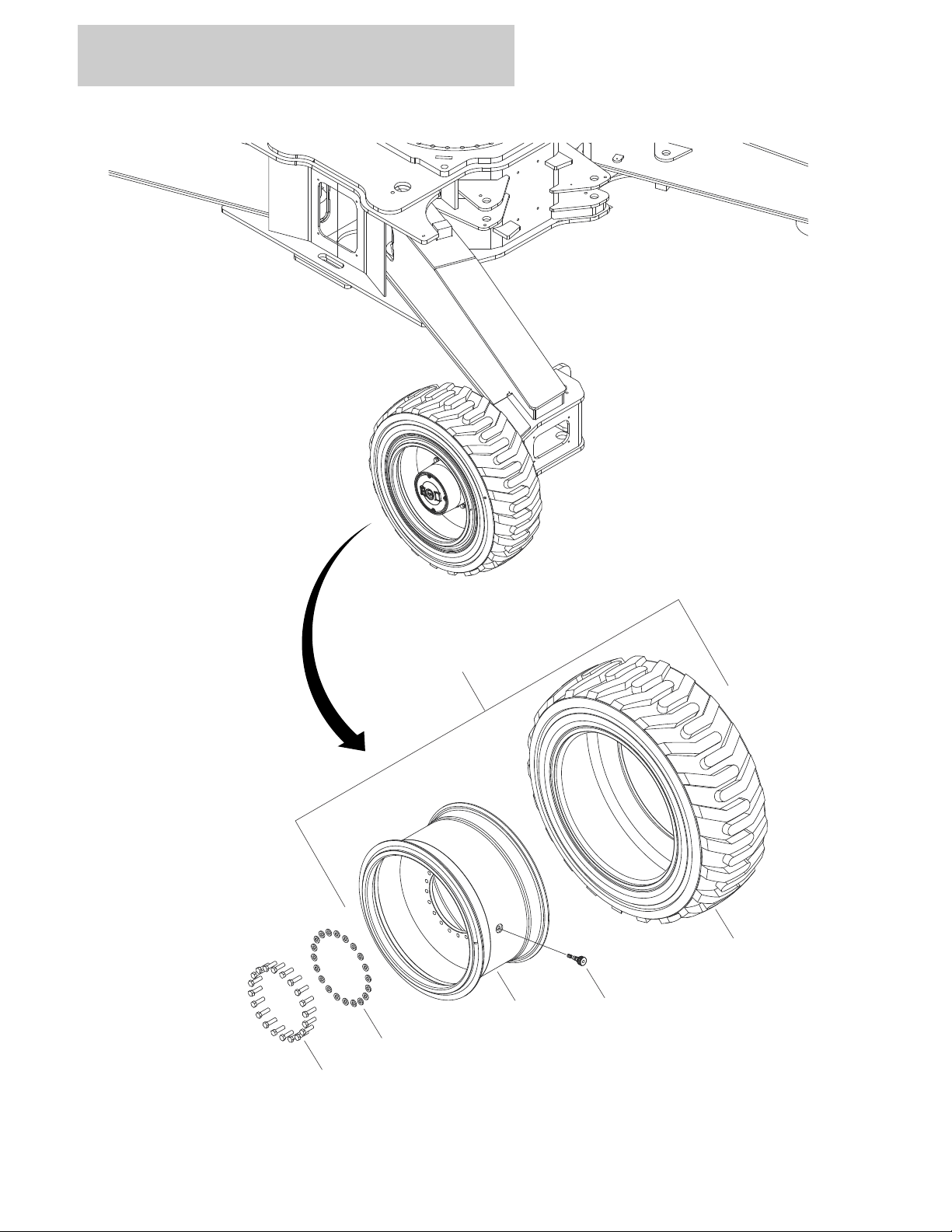
FIGURE 1-6. TIRE/WHEEL INSTALLATION - IN445/50D710 FOAM-FILLED
1-14 1850SJ 3121620
Page 25

SECTION 1 FRAME
FIGURE 1-6. TIRE/WHEEL INSTALLATION - IN445/50D710 FOAM-FILLED
ITEM # PART NUMBER QTY. DESCRIPTION REV.
1001157216 Ref TIRE/WHEEL INSTALLATION - IN445/50D710FOAM-FILLED B
Ref Note: Requires ballast/foam filling to manufacturer’s
specifications prior to installing on a machine. Refer to
Operation & Safety or Service & Maintenance Manuals.
Purchase individual tire and/or rim only if able to foam fill tire &
wheel assembly, otherwise, purchase complete.
1 0701619001 80 Bolt M16 x 55 (20 Per Wheel)
2 1001172356 80 Washer 5/8 (20 Per Wheel)
3 1001147616 2 Tire/Wheel (RH Side) (See Items 101-103 for Breakdown)
3 1001149711 2 Tire/Wheel (LH Side) (See Items 101-103 for Breakdown)
1001147616 Ref TIRE/WHEEL ASSEMBLY (RH SIDE) D
1001149711 Ref TIRE/WHEEL ASSEMBLY (LH SIDE) D
101 1001147617 4 Wheel (1 per Tire/Wheel)
102 1001147618 4 Tire (1 per Tire/Wheel)
103 1001157467 4 Valve (1 per Tire/Wheel)
3121620 1850SJ 1-15
Page 26

SECTION 1 FRAME
1001157706_PG 1 OF 3
31
5
5
5
19
19
19
15
2
26
26
22
21
21
10
1
6
1
7
20
29
31
31
19
35
5
5
FIGURE 1-7. VALVES INSTALLATION - FRAME
1-16 1850SJ 3121620
Page 27

SECTION 1 FRAME
FIGURE 1-7. VALVES INSTALLATION - FRAME
ITEM # PART NUMBER QTY. DESCRIPTION REV.
1001157706 Ref VALVES - FRAME G
1 0100011 AR Compound, Locking
2 0641422 2 Bolt 1/4 x 2-3/4
5 0760812 8 Bolt M8 x 25
6 0761012 4 Bolt M10 x 25
7 0761218001 4 Bolt M12 x 50
10 3291205001 4 Nut M12
11 3311405 4 Nut 1/4
15 4641155 1 Manifold, Junction
16 4711400 4 Washer 1/4
19 4811900001 8 Washer M8
20 4812000 4 Washer M10
21 4812100001 4 Washer M12
29 1001164354 1 Bracket
30 1001157198 1 Valve, Traction (See TRACTION VALVE ASSEMBLY for
Breakdown)
31 1001157207 2 Valve, Steer/Axle Extend (See STEER/AXLE EXTEND VALVE
ASSEMBLY for Breakdown)
35 1001118274 8 Nut M8
3121620 1850SJ 1-17
Page 28
SECTION 1 FRAME
14
9
104
105
104
105
2
13
1
13
102
102
106
103
3
102
102
4
1001157198
7
10
102
12
15
6
8
102
102
106
102
11
101
5
16
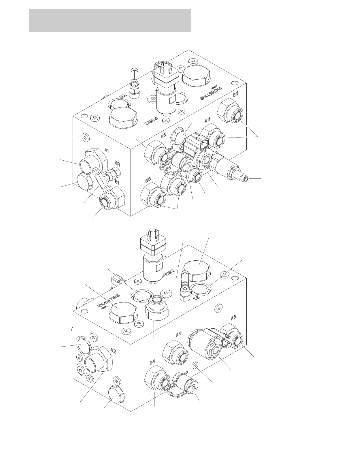
FIGURE 1-8. TRACTION VALVE ASSEMBLY
1-18 1850SJ 3121620
Page 29

SECTION 1 FRAME
FIGURE 1-8. TRACTION VALVE ASSEMBLY
ITEM # PART NUMBER QTY. DESCRIPTION REV.
1001157198 Ref TRACTION VALVE ASSEMBLY E
1 7012941 1 Cartridge, Solenoid Less Coil
1 7010543 1 Kit, Seal
2 7012941 1 Cartridge, Solenoid Less Coil
2 7010543 1 Kit, Seal
3 70004383 1 Cartridge, Relief
3 7012998 1 Kit, Seal
4 70004384 1 Cartridge, Load Shuttle
4 7012973 1 Kit, Seal
5 70004385 1 Cartridge
5 70002978 1 Kit, Seal
6 70004017 1 Cartridge, Flow Divider
6 7021625 1 Kit, Seal
7 70004017 1 Cartridge, Flow Divider
7 7021625 1 Kit, Seal
8 70003408 1 Cartridge, Check
8 7022399 1 Kit, Seal
9 70003408 1 Cartridge, Check
9 7022399 1 Kit, Seal
10 70003408 1 Cartridge, Check
10 7022399 1 Kit, Seal
11 70003408 1 Cartridge, Check
11 7022399 1 Kit, Seal
12 70000803 1 Cartridge, Pressure Switch
13 70002386 2 Coil
14 7017493 1 Orifice
15 7017493 1 Orifice
16 70004386 1 Orifice
101 2111016 2 Fitting, Straight ORB/ORFS
102 2111012 10 Fitting, Straight ORB/ORFS
103 2110810 1 Fitting, Straight ORB/ORFS
104 2220415 2 Fitting, Straight JIC/ORB
105 2220861 2 Fitting, Tee JIC/ORB
106 2221086 2 Fitting, Test
3121620 1850SJ 1-19
Page 30
SECTION 1 FRAME
4
8
11
11
11
104
104
104
104
104
104
104
104
102
103
105
105
10
11
11
11
5
7
9
101
1
2
3
1001157207
FIGURE 1-9. STEER/AXLE EXTEND VALVE ASSEMBLY
1-20 1850SJ 3121620
Page 31

SECTION 1 FRAME
FIGURE 1-9. STEER/AXLE EXTEND VALVE ASSEMBLY
ITEM # PART NUMBER QTY. DESCRIPTION REV.
1001157207 Ref STEER/AXLE EXTEND VALVE ASSEMBLY C
1 70004459 1 Valve, Direction Control
1 7012773 1 Kit, Seal
1 70004460 2 Coil
1 7021375 2 Nut, Coil
1 70004461 2 O-Ring, Solenoid Pole
2 70004462 1 Valve, Direction Control
2 7012773 1 Kit, Seal
2 70004463 2 Coil
2 7021375 2 Nut, Coil
2 70004461 2 O-Ring, Solenoid Pole
3 70004462 1 Valve, Direction Control
3 7012773 1 Kit, Seal
3 70004463 2 Coil
3 7021375 2 Nut, Coil
3 70004461 2 O-Ring, Solenoid Pole
4 70004464 1 Cartridge, Relief
4 70004055 1 Kit, Seal
5 70004464 1 Cartridge, Relief
5 70004055 1 Kit, Seal
6 70004464 1 Cartridge, Relief
6 70004055 1 Kit, Seal
7 70004464 1 Cartridge, Relief
7 70004055 1 Kit, Seal
8 70004464 1 Cartridge, Relief
8 70004055 1 Kit, Seal
9 70004464 1 Cartridge, Relief
9 70004055 1 Kit, Seal
10 70004465 1 Cartridge, Flow Divider
10 70004164 1 Kit, Seal
11 2221086 6 Fitting, Test
101 Not Available 12 Capscrew #10 x 2 (Note: Purchase Locally)
102 NSS Bracket
103 0641504 4 Bolt 5/16-18 x 1/2
104 2220371 8 Fitting, Straight JIC/ORB
105 2110810 2 Fitting, Straight ORB/ORFS
3121620 1850SJ 1-21
Page 32

SECTION 1 FRAME
8
9
12
15
15
18
18
22
23
32
1001156522_PG 1 OF 2
FIGURE 1-10. ELECTRICAL COMPONENTS INSTALLATION - FRAME
1-22 1850SJ 3121620
Page 33

SECTION 1 FRAME
FIGURE 1-10. ELECTRICAL COMPONENTS INSTALLATION - FRAME
ITEM # PART NUMBER QTY. DESCRIPTION REV.
1001156522 Ref ELECTRICAL COMPONENTS INSTALLATION - FRAME H
8 0761218001 4 Bolt M12 x 50
9 3290605 5 Nut M6
12 3291205001 4 Nut M12
15 4811700 10 Washer M6
18 4812100001 8 Washer M12
22 1001150162 1 Module, Control (Note: Control System must be recalibrated when
module is replaced)
23 1001118878 5 Capscrew M6 x 55
30 1001149975 1 Harness, Chassis (Not Shown - See ELECTRICAL SECTION for
Breakdown)
32 1001164354 1 Bracket
3121620 1850SJ 1-23
Page 34

SECTION 1 FRAME
1
2
1
2
1
2
1
2
1
2
1
2
4
4
4
4
3
3
1001157670
FIGURE 1-11. COVERS INSTALLATION - FRAME
1-24 1850SJ 3121620
Page 35

SECTION 1 FRAME
FIGURE 1-11. COVERS INSTALLATION - FRAME
ITEM # PART NUMBER QTY. DESCRIPTION REV.
1001157670 Ref COVERS INSTALLATION B
1 0100011 AR Compound, Locking
2 5251210001 24 Bolt M12 x 20
3 1001155561 2 Cover
4 1001156867 4 Cover
3121620 1850SJ 1-25
Page 36

SECTION 1 FRAME
FIGURE 1-11. COVERS INSTALLATION - FRAME (CONTINUED)
ITEM # PART NUMBER QTY. DESCRIPTION REV.
1-26 1850SJ 3121620
Page 37

SECTION 2
TURNTABLE
3121620 1850SJ 2-1
Page 38

SECTION 2 TURNTABLE
1
1
13
1
22
1
6
8
32
20
18
18
23
33
1001157706_PG 2 OF 3
FIGURE 2-1. VALVES & HYDRAULIC FILTERS INSTALLATION - TURNTABLE
2-2 1850SJ 3121620
Page 39

SECTION 2 TURNTABLE
FIGURE 2-1. VALVES & HYDRAULIC FILTERS INSTALLATION - TURNTABLE
ITEM # PART NUMBER QTY. DESCRIPTION REV.
1001157706 Ref VALVES & HYDRAULIC FILTERS INSTALLATION - TURNTABLE G
1 0100011 AR Compound, Locking
6 0761012 4 Bolt M10 x 25
8 2120217 1 Filter
8 70002097 1 Element
8 70001499 1 Kit, Seal
8 70004328 1 Plug, Indicator
13 1001173846 4 Screw 3/8-16 x 3/4
14 3900316 4 Screw 3/8-16 x 1
18 4711600001 12 Washer 3/8
20 4812000 4 Washer M10
22 88261128 4 Screw 3/8-16 x 1
23 1001108617 1 Filter
23 70002231 1 Element
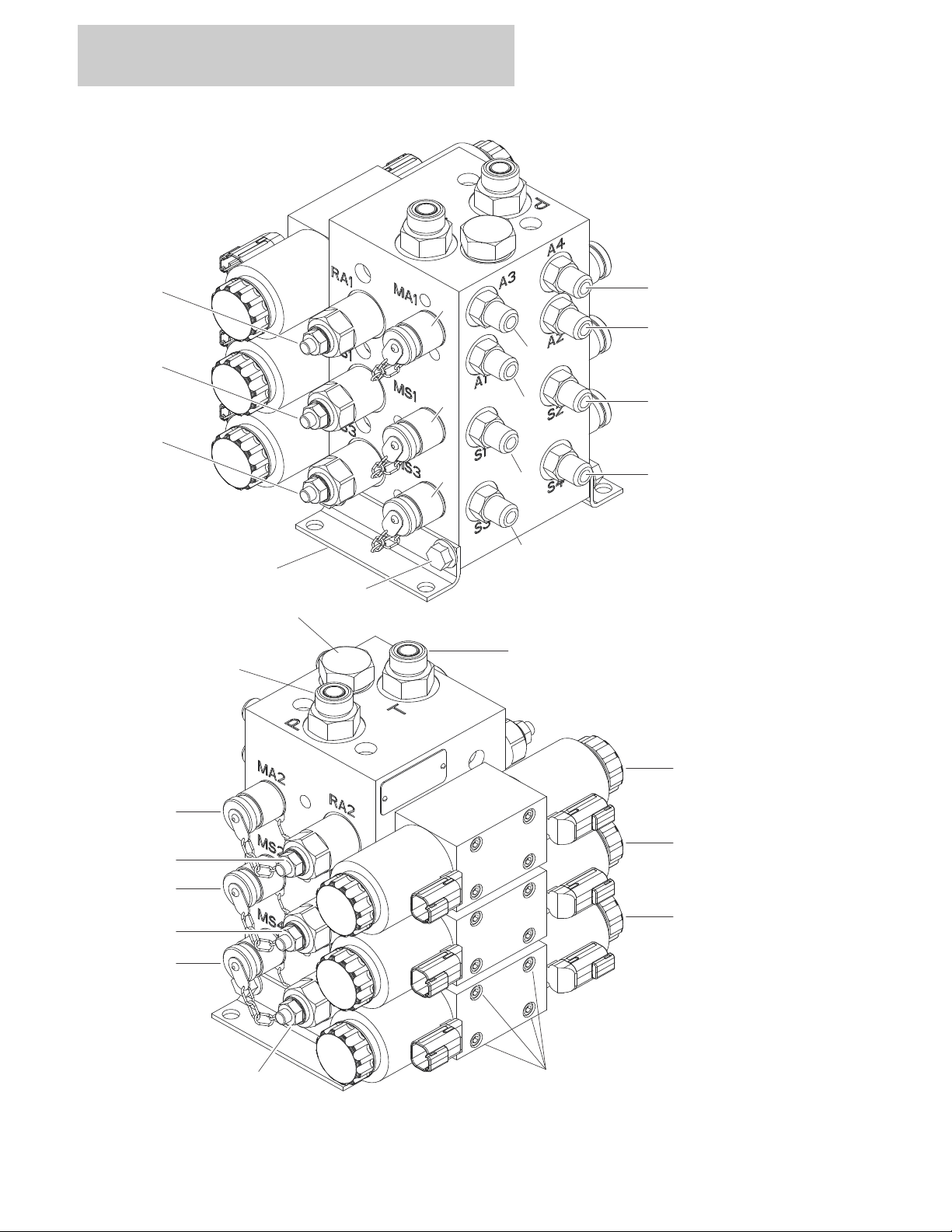
32 1001158406 1 Main Valve Assembly (See MAIN VALVE ASSEMBLY for
Breakdown)
33 1001158412 1 Filter
33 1001161232 1 Element
3121620 1850SJ 2-3
Page 40

SECTION 2 TURNTABLE
1001158406
115
109
123
119
26
16
107
15
106
31
122
14
122131052010221102
12
107
11
105
19
107
17
104
17
10428102
118
121
113
111
103
22
113
117
22
117
18
12
11
103
119
11
18
19
25
30
116
29
120
114
103
112
119
118
103
22
29
103
29
103
110
103
23
24
17
13
27
124
FIGURE 2-2. MAIN VALVE ASSEMBLY
2-4 1850SJ 3121620
Page 41

SECTION 2 TURNTABLE
FIGURE 2-2. MAIN VALVE ASSEMBLY
ITEM # PART NUMBER QTY. DESCRIPTION REV.
1001158406 Ref MAIN VALVE ASSEMBLY E
Ref Note: Some Parts Not Available at Time of Printing
11 See Note 3 Cartridge, Check
11 See Note 3 Kit, Seal
12 See Note 2 Cartridge, Check
12 See Note 2 Kit, Seal
13 See Note 2 Cartridge, Solenoid
13 See Note 2 Kit, Seal
13 See Note 2 Coil
14 See Note 1 Orifice
15 See Note 1 Cartridge, Directional
15 See Note 1 Kit, Seal
16 See Note 1 Cartridge, Pressure Reducing
16 See Note 1 Kit, Seal
17 See Note 3 Cartridge, Solenoid
17 See Note 3 Kit, Seal
17 See Note 3 Coil
18 See Note 3 Cartridge, Shuttle
18 See Note 3 Kit, Seal
19 See Note 2 Cartridge, Dump
19 See Note 2 Kit, Seal
19 See Note 2 Coil
20 See Note 1 Valve
20 See Note 1 Kit, Seal
20 See Note 2 Coil
20 See Note 2 Nut
21 See Note 1 Valve
21 See Note 1 Kit, Seal
21 See Note 2 Coil
21 See Note 2 Nut
22 See Note 4 Cartridge, Relief Valve
22 See Note 4 Kit, Seal
23 See Note 1 Cartridge, Flow Control
23 See Note 1 Kit, Seal
24 See Note 1 Cartridge, Pilot Check
24 See Note 1 Kit, Seal
25 See Note 3 Cartridge, Solenoid
25 See Note 3 Kit, Seal
25 See Note 3 Coil
26 See Note 3 Cartridge, Relief Valve
26 See Note 3 Kit, Seal
27 See Note 3 Cartridge, Check
27 See Note 3 Kit, Seal
28 See Note 1 Valve
28 See Note 1 Kit, Seal
28 See Note 2 Coil
28 See Note 2 Nut
3121620 1850SJ 2-5
Page 42

SECTION 2 TURNTABLE
FIGURE 2-2. MAIN VALVE ASSEMBLY (CONTINUED)
ITEM # PART NUMBER QTY. DESCRIPTION REV.
29 See Note 2 Cartridge, Counterbalance
29 See Note 2 Kit, Seal
30 See Note 1 Cartridge, Throttle
30 See Note 1 Kit, Seal
31 See Note 1 Plug
102 3931032 12 Capscrew #10 x 2
103 2221086 8 Fitting, Test
104 See Note 2 Kit, Lockingt
105 See Note 2 Kit, Lockingt
106 See Note 1 Kit, Lockingt
107 See Note 3 Kit, Lockingt
109 See Note 1 Sensor, Thermostat
109 3930606 1 Capscrew #6 x 3/8-16
110 See Note 1 Switch, Transducer Switch
111 2110406 1 Fitting, Straight ORB/ORFS
112 2220373 1 Fitting, Straight JIC/ORB
113 2111010 3 Fitting, Straight ORB/ORFS
113 2110810 1 Fitting, Straight ORB/ORFS
114 2131616 1 Fitting, Elbow ORFS/ORB
115 2220415 1 Fitting, Straight JIC/ORB
116 2220582 1 Fitting, Straight JIC/ORB
116 2220371 1 Fitting, Straight JIC/ORB
117 2220373 4 Fitting, Straight JIC/ORB
118 2220947 2 Fitting, Straight JIC/ORB
119 2111012 1 Fitting, Straight JIC/ORB
119 2220865 2 Fitting, Straight JIC/ORB
120 88662070 1 Fitting, 90 JIC/ORB
121 See Note 1 Fitting, Straight
122 See Note 2 Plug, Zero Leak
123 See Note 1 Plug, Zero Leak
124 See Note AR Plug, Zero Leak
2-6 1850SJ 3121620
Page 43

SECTION 2 TURNTABLE
FIGURE 2-2. MAIN VALVE ASSEMBLY (CONTINUED)
ITEM # PART NUMBER QTY. DESCRIPTION REV.
3121620 1850SJ 2-7
Page 44

SECTION 2 TURNTABLE
1001155979
1
8
7
9
1
2
7
6
6
3
5
FIGURE 2-3. TURNTABLE BEARING INSTALLATION
2-8 1850SJ 3121620
Page 45

SECTION 2 TURNTABLE
FIGURE 2-3. TURNTABLE BEARING INSTALLATION
ITEM # PART NUMBER QTY. DESCRIPTION REV.
1001153979 Ref TURNTABLE BEARING INSTALLATION C
1 0100019 AR Compound, Locking
2 0712435 36 Bolt M24 x 180 Grade 10.9
3 2180002 3 Fitting, Grease
4 2180344 3 Fitting, Bulkhead NPT
6 27501032 3 Hose
7 5242400 71 Washer M24
8 1001097587 35 Bolt M24 x 150 Grade 10.9
9 1001149823 1 Bearing, Swing
3121620 1850SJ 2-9
Page 46

SECTION 2 TURNTABLE
1001154119
1
2
3
4
4
FIGURE 2-4. TURNTABLE LOCK INSTALLATION
2-10 1850SJ 3121620
Page 47

SECTION 2 TURNTABLE
FIGURE 2-4. TURNTABLE LOCK INSTALLATION
ITEM # PART NUMBER QTY. DESCRIPTION REV.
1001154119 Ref TURNTABLE LOCK INSTALLATION A
1 1260017 8in/20cm Chain
2 3421563 1 Pin
3 3421565 1 Pin
4 3760170 2 Ring
3121620 1850SJ 2-11
Page 48

SECTION 2 TURNTABLE
1001153981
12
12
1
2
1
2
2
2
2
2
2
7
7
7
7
7
10
10
11
11
6
6
5
5
9
3
8
8
4
FIGURE 2-5. SWING DRIVE INSTALLATION
2-12 1850SJ 3121620
Page 49

SECTION 2 TURNTABLE
FIGURE 2-5. SWING DRIVE INSTALLATION
ITEM # PART NUMBER QTY. DESCRIPTION REV.
1001153981 Ref SWING DRIVE INSTALLATION B
1 0100019 AR Compound, Locking
2 0682220 12 Bolt 3/4 x 2-1/2 Grade 8
3 0701018 3 Bolt M10 x 50
4 3291005 3 Nut M10
5 3312002 2 Nut 5/8-11
6 3952020 2 Setscrew 5/8-11 x 2-1/2
7 4740057 10 Washer,
8 4812000 6 Washer M10
9 1001150725 1 Shield
10 1001153983 2 Bar
11 1001153984 2 Swing Hub/Brake/Motor Assembly (See SWING HUB/BRAKE/
MOTOR ASSEMBLY for Breakdown)
12 1001154377 2 Shim
3121620 1850SJ 2-13
Page 50

1001153984
1
2
3
4
6
7
7
7
8910
20
28 29 30 24 31
21
22
23
24
26
25
27
12
13
14
15
16
17
18
19
19
11
11
5
32
33
34
3
4
35
35
36
37
38
39
40
414
243
4951444
8
4546475
2
535554
50
SECTION 2 TURNTABLE
FIGURE 2-6. SWING HUB/BRAKE/ MOTOR ASSEMBLY
2-14 1850SJ 3121620
Page 51

SECTION 2 TURNTABLE
FIGURE 2-6. SWING HUB/BRAKE/ MOTOR ASSEMBLY
ITEM # PART NUMBER QTY. DESCRIPTION REV.
1001153984 Ref HUB/BRAKE/MOTOR - SWING D
1 70004466 1 Shaft
2 70004467 1 Ring
3 NSS Seal, Oil (Use p/n 70004489)
4 70004468 1 Bearing
5 70004469 1 Plug with O-Ring
6 70004470 1 Support, Output
7 70002057 5 Plug with O-Ring
8 70004471 1 Bearing
9 70004472 1 Washer
10 70004473 1 Nut, Ring
11 NSS O-Ring (Use p/n 70004489)
12 70004474 1 Ring, Planetary
13 70004475 1 Reduction, Gear - Complete
14 70004476 1 Pinion
15 70004477 1 Spacer
16 70004478 4 Pin, Spring
17 70004479 1 Spacer
18 70004480 8 Capscrew M10x55
19 NSS O-Ring (Use p/n 70004489)
20 70004481 1 Ring, Planetary
21 70004482 1 Reduction, Gear - Complete
22 70004483 1 Pinion
23 NSS Ring (Use p/n 70004488)
24 NSS Washer (Use p/n 70004488)
25 NSS Housing, Brake (Use p/n 70004488)
26 NSS Plug (Use p/n 70004488)
27 NSS Plug (Use p/n 70004488)
28 NSS Capscrew M8x35 (Use p/n 70004488)
29 NSS Plug (Use p/n 70004488)
30 NSS Washer (Use p/n 70004488)
31 NSS Shaft, Input (Use p/n 70004488)
32 NSS Disc, Steel (Use p/n 70004488)
33 NSS Disc (Use p/n 70004488)
34 NSS Seal (Use p/n 70004488 or 70004490)
35 NSS O-Ring (Use p/n 70004488 or 70004490)
36 NSS Spacer (Use p/n 70004488)
37 NSS Seal (Use p/n 70004488 or 70004490)
38 NSS O-Ring (Use p/n 70004488 or 70004490)
39 NSS Piston, Brake (Use p/n 70004488)
40 NSS Spring, Brake (Use p/n 70004488)
41 NSS O-Ring (Use p/n 70004488 or 70004490)
42 NSS Cover (Use p/n 70004488 or 70004490)
43 NSS Screw M6x25 (Use p/n 70004488)
44 NSS O-Ring (Use p/n 70004488 or 70004490)
45 70004484 2 Lug, Lifting
46 70004485 4 Washer, Lock
47 70004486 2 Capscrew M12x25
3121620 1850SJ 2-15
Page 52

SECTION 2 TURNTABLE
FIGURE 2-6. SWING HUB/BRAKE/ MOTOR ASSEMBLY (CONTINUED)
ITEM # PART NUMBER QTY. DESCRIPTION REV.
48 70004487 2 Capscrew M12x35
49 70004491 1 Motor
Ref Note: Seal Kit is the on replacement component available.
therwise, replacement complete motor.
50 70004492 1 Kit, Seal - Motor
51 70004493 1 O-Ring
52 70004494 2 Bolt
53 70004488 1 Kit, Brake (Includes Items 23-44)
54 70004489 1 Kit, Seal - Gearbox (Includes Items 3, 11 &19)
55 70004490 1 Kit, Brake Seal (Includes Items 34, 35, 37, 38 &44)
2-16 1850SJ 3121620
Page 53

SECTION 2 TURNTABLE
FIGURE 2-6. SWING HUB/BRAKE/ MOTOR ASSEMBLY (CONTINUED)
ITEM # PART NUMBER QTY. DESCRIPTION REV.
3121620 1850SJ 2-17
Page 54

SECTION 2 TURNTABLE
1001154192
2
6
6
4
7
813
1
5
6
FIGURE 2-7. COUPLING/COLLECTOR RING INSTALLATION
2-18 1850SJ 3121620
Page 55

SECTION 2 TURNTABLE
FIGURE 2-7. COUPLING/COLLECTOR RING INSTALLATION
ITEM # PART NUMBER QTY. DESCRIPTION REV.
1001154192 Ref COUPLING/COLLECTOR RING INSTALLATION A
1 0100011 AR Compound, Locking
2 0701224 2 Bolt M12 x 80
3 0761216 3 Bolt M12 x 40
4 3291205 2 Nut M12
5 3322201 2 Nut 3/4
6 4812102 7 Washer M12
7 1001146978 1 Coupling/Collector Ring Assembly (See ELECTRICAL SECTION
for Breakdown)
8 1001154196 1 Bracket
3121620 1850SJ 2-19
Page 56

SECTION 2 TURNTABLE
1001154006
3
12
12
7
14
5
10
1
17
2
6
2
6
9
8
9
9
2
8
8
6
13A
101
13
16
4
11
11
7
15
FIGURE 2-8. TANKS INSTALLATION
2-20 1850SJ 3121620
Page 57

SECTION 2 TURNTABLE
FIGURE 2-8. TANKS INSTALLATION
ITEM # PART NUMBER QTY. DESCRIPTION REV.
1001154006 Ref TANKS INSTALLATION C
1 0100011 AR Compound, Locking
2 0100020 AR Sealant
3 0701015 4 Bolt M10 x 35
4 0701017 6 Bolt M10 x 45
5 0731007 5 Screw, Machine #10-24 x 7/8
6 2200222 3 Plug
7 3291007 10 Nut M10
8 3311601 4 Nut 3/8-16
9 4711600 4 Washer 3/8
10 4751000 5 Washer #10
11 4812000 12 Washer M10
12 4812002 8 Washer M10
13 1001108579 1 Tank, Fuel
13A 70004413 1 Tube, Pickup
14 1001109048 1 Gauge, Fuel
14 3960525 1 Gasket (Gauge to Tank)
15 1001147879 1 Tank, Hydraulic (See HYDRAULIC TANK ASSEMBLY for
Breakdown)
16 1001154005 1 Tray
17 1001110059 1 Strap
Ref FUEL TANK CAP
101 7016314 1 Cap - Standard Black Non-Locking (Part of Item 13)
101 1120487 1 Cap - Optional Blue Lockable (Lock Not Included) (Not Shown)
3121620 1850SJ 2-21
Page 58

SECTION 2 TURNTABLE
1001147879
2
11
10
4
3
5
7
18
9
16
8
16
17
6
19
20
FIGURE 2-9. HYDRAULIC TANK ASSEMBLY
2-22 1850SJ 3121620
Page 59

SECTION 2 TURNTABLE
FIGURE 2-9. HYDRAULIC TANK ASSEMBLY
ITEM # PART NUMBER QTY. DESCRIPTION REV.
1001147879 Ref HYDRAULIC TANK ASSEMBLY G
2 NSS Gasket (Use p/n 70004150)
3 NSS Element, Filter (Use p/n 70004150)
4 Not Available 1 Cover
5 70004412 1 Spring
6 70002838 1 Cap, Fill
7 NSS Breather (Use p/n 70004150)
8 7024441 1 Gauge
9 See Note 1 Plug (Note: Purchase Locally)
10 See Note 6 Washer 5/16in Stainless Steel (Note: Purchase Locally)
11 See Note 6 Bolt 5/16-18 x 1 Stainless Steel (Note: Purchase Locally)
16 See Note AR Loctite #243 (Note: Purchase Locally)
17 See Note AR Lubricant (Note: Purchase Locally)
18 See Note AR Loctite #565 (Note: Purchase Locally)
19 70004411 1 Decal, Service
20 70004150 1 Kit, Service (Includes Item 2,3 & 7)
3121620 1850SJ 2-23
Page 60

SECTION 2 TURNTABLE
1001154034
3
12
11
5
7
19 18
2
1
9
10
16
20
8
17413
6
13
19
18
15413
13
6
FIGURE 2-10. AUXILIARY POWER/BATTERIES INSTALLATIONS
2-24 1850SJ 3121620
Page 61

SECTION 2 TURNTABLE
FIGURE 2-10. AUXILIARY POWER/BATTERIES INSTALLATIONS
ITEM # PART NUMBER QTY. DESCRIPTION REV.
1001154034 Ref AUXILIARY POWER/BATTERIES INSTALLATIONS C
1 0236768 4 Bolt, TIe-Down
2 0400020 2 Battery
3 0700610 2 Bolt M6 x 20
4 0701018 8 Bolt M10 x 50
5 3290607 2 Nut M6
6 3291007 8 Nut M10
7 3740067 1 Relay
8 3980006 2 Seat, Battery
9 4711600 4 Washer 3/8
10 4761600 4 Washer 3/8
11 4791400 2 Washer 1/4
12 4811700 2 Washer M6
13 4812000 16 Washer M10
15 3600465 1 Pump/Motor, Auxiliary (See AUXILIARY PUMP/MOTOR
ASSEMBLY for Breakdown)
16 1001154035 2 Plate
17 1001164056 1 Bracket
18 1001154144 1 Cable, Electrical (Positive)
19 1001154145 1 Cable, Electrical (Negative)
20 4420038 34in/
85cm
Tape
3121620 1850SJ 2-25
Page 62

SECTION 2 TURNTABLE
34523
3600465
FIGURE 2-11. AUXILIARY PUMP AND MOTOR ASSEMBLY
2-26 1850SJ 3121620
Page 63

SECTION 2 TURNTABLE
FIGURE 2-11. AUXILIARY PUMP AND MOTOR ASSEMBLY
ITEM # PART NUMBER QTY. DESCRIPTION REV.
3600465 Ref. AUXILIARY PUMP & MOTOR ASSEMBLY C
1 7010924 1 Motor
1 7010639 2 Brush
1 7010640 8 Spring, Brush
1 7011044 1 Gasket, Adapter to Motor
2 70000998 1 Coupling
2 70000999 1 Key, Woodruff
2 See Note 1 Adapter
2 Ref Note: Not Available for Purchase
3 70001001 1 Kit, Pump (Includes Pump, Adapter to Motor Gasket p/n 7011044
& Mounting Hardware)
3 7011043 4 Screw
3 7011048 4 Washer
3 70001000 1 Kit, Seal (Includes Adapter to Motor Gasket p/n 7011044, Pump to
Adapter Gasket, Shaft Seal & O-Rings for Hex Caps on Adapter)
4 See Note 1 Ball
4 Ref Note: Not Available for Purchase
4 See Note 1 Spring
4 Ref Note: Not Available for Purchase
4 See Note 1 Screw, Valve Adjustment
4 Ref Note: Not Available for Purchase
5 See Note 1 Ball & Spring Assembly
5 Ref Note: Not Available for Purchase
5 See Note 1 Plug
5 Ref Note: Not Available for Purchase
3121620 1850SJ 2-27
Page 64

SECTION 2 TURNTABLE
1001156522_PG 2 OF 2
40
39
15
9
33
25
2
9
15
24
13
14
10
16
41
6
10
16
20
6
101634
SEE SECTION 3
FOR CALL OUT
ITEM 43 LOCATED ON T/T
NEAR PUMPS - SHOWN
HERE FOR CLARITY
1
5
19
42
36
15
15
15
4
15
4
15
9
9
9
4
15
9
15
444647
6
10
16
20
50
1
6
16
43
43
21
49
4
4848521117
17
7
48
52
FIGURE 2-12. TURNTABLE ELECTRICAL COMPONENTS INSTALLATION
2-28 1850SJ 3121620
Page 65

SECTION 2 TURNTABLE
FIGURE 2-12. TURNTABLE ELECTRICAL COMPONENTS INSTALLATION
ITEM # PART NUMBER QTY. DESCRIPTION REV.
1001156522 Ref TURNTABLE ELECTRICAL COMPONENTS INSTALLATION H
1 0100035 AR Compound, Locking
2 0700618 2 Bolt M6 X 50
4 0760612 5 Bolt M6 X 25
5 1001164726 4 Capscrew M8 X 20
6 0760812 10 Bolt M8 X 25
7 0761014 1 Bolt, M10 X 30
9 3290605 16 Nut, M6
10 3290807 9 Nut, M8
11 3291007 1 Nut, M10
13 4460496 1 Washer, Terminal
14 4460497 1 Nut, Terminal
15 4811700 24 Washer M6
16 4811900 13 Washer M8
17 4812000 2 Washer M10
19 8310686 4 Nut, Retainer, M8
20 8406201 2 Clip
21 1320041 1 Clamp
24 1001174871 2 Fuse, Power Module
25 1001135027 1 Bussbar
26 1001149970 1 Harness -Drive Pump (Not Shown - See ELECTRICAL SECTION
for Breakdown)
27 1001149972 1 Harness - Turntable (Not Shown - See ELECTRICAL SECTION for
Breakdown)
28 1001149973 1 Harness - Ground Control Panel (Not Shown - See ELECTRICAL
SECTION for Breakdown)
29 1001149974 1 Harness - Main Valve (Not Shown - See ELECTRICAL SECTION
for Breakdown)
31 1001149979 1 Harness - Blam (Not Shown - See ELECTRICAL SECTION for
Breakdown)
33 1001154512 1 Panel, Ground Control (See GROUND CONTROL CONSOLE
ASSEMBLY for Breakdown)
34 1001156107 6 Holder, Cable
34 Ref Note: Qty 4 Not Shown - Located Behind Hydraulic Tank
35 1001156135 1 Harness - Fuel Pump (Not Shown - See ELECTRICAL SECTION
for Breakdown)
36 1001156859 1 Panel, Electrical (See ELECTRICAL PANEL ASSEMBLY for
Breakdown)
37 1001158922 1 Kit, Battery Cable (Not Shown - See ELECTRICAL SECTION for
Breakdown)
39 1001151895 1 Sensor, Tilt (See ELECTRICAL SECTION for Breakdown)
40 0760614 2 Bolt M6 X 30
41 0760815 1 Bolt M8 X 35
42 2920129 10 Lamp, Display
43 1001155967 4 Holder, Side Mount
44 0700610 2 Bolt M6 X 20
46 3740067 1 Relay
47 4791400 2 Starwasher 1/4
48 3311601 4 Nut 3/8-16
3121620 1850SJ 2-29
Page 66

SECTION 2 TURNTABLE
FIGURE 2-12. TURNTABLE ELECTRICAL COMPONENTS INSTALLATION (CONTINUED)
ITEM # PART NUMBER QTY. DESCRIPTION REV.
49 4811702 1 Washer M6
50 1001118274 2 Nut M8
51 1001163631 4 Cable, MTS Connection (Not Shown - See ELECTRICAL SEC-
TION for Breakdown)
52 6611172 2 Cable, Ground to Frame (
53 1001157646 1 Cable, Load Sensor (Not Shown - Runs from Item 36 RH Module
to Lift Cylinder) (See ELECTRICAL SECTION for Breakdown)
2-30 1850SJ 3121620
Page 67

SECTION 2 TURNTABLE
FIGURE 2-12. TURNTABLE ELECTRICAL COMPONENTS INSTALLATION (CONTINUED)
ITEM # PART NUMBER QTY. DESCRIPTION REV.
3121620 1850SJ 2-31
Page 68

SECTION 2 TURNTABLE
1001154512
11
9
1
14
3
4
12
4
9
6
6
6
6
6
6
6
6
10
8
7
5
FIGURE 2-13. GROUND CONTROL CONSOLE ASSEMBLY
2-32 1850SJ 3121620
Page 69

SECTION 2 TURNTABLE
FIGURE 2-13. GROUND CONTROL CONSOLE ASSEMBLY
ITEM # PART NUMBER QTY. DESCRIPTION REV.
1001154512 Ref GROUND CONTROL CONSOLE ASSEMBLY C
1 1670829 1 Bezel
3 2760105 1 Housing, Light
4 3290505 2 Nut M5
5 4060906 1 Guard, Switch
6 4360328 8 Switch, Toggle
7 4360475 1 Switch, Push-Pull Emergency
7 7020175 1 Cap
7 7020176 1 Block, Contact
8 4360476 2 Block, Contact
9 1001099125 2 Screw M5 x 16 Grade 10.9
10 1001109503 1 Gauge
11 1001154513 1 Panel
12 4360274 1 Switch, Pushbutton
14 1001156232 1 Decal - Ground Control
3121620 1850SJ 2-33
Page 70

SECTION 2 TURNTABLE
3
3A
3
1
1
2
0259666
0259667
FIGURE 2-14. KEY SWITCH - ANSI, ANSI EXPORT, AUSTRALIAN AND CSA SPECS
2-34 1850SJ 3121620
Page 71

SECTION 2 TURNTABLE
FIGURE 2-14. KEY SWITCH - ANSI, ANSI EXPORT, AUSTRALIAN AND CSA SPECS
ITEM # PART NUMBER QTY. DESCRIPTION REV.
0259666 Ref. KEY SWITCH INSTALLATION (ANSI, ANSI EXPORT, AUSTRALIAN
& CSA SPECS)
1 3910804 6 Screw #8 x 1/8
2 1001151393 Shim .063
3 4360469 1 Keyswitch
3A 2860030 1 Key, Replacement
B
3121620 1850SJ 2-35
Page 72

SECTION 2 TURNTABLE
3
3A
3
1
1
2
0259666
0259667
FIGURE 2-15. KEY SWITCH - CE SPECS
2-36 1850SJ 3121620
Page 73

SECTION 2 TURNTABLE
FIGURE 2-15. KEY SWITCH - CE SPECS
ITEM # PART NUMBER QTY. DESCRIPTION REV.
0259667 Ref. KEY SWITCH INSTALLATION (CE SPECS) B
1 3910804 6 Screw #8 x 1/8
2 1001151393 Shim .063
3 4360470 1 Keyswitch
3A 2860030 1 Key, Replacement
3121620 1850SJ 2-37
Page 74

SECTION 2 TURNTABLE
1
1001121826_PG 1 OF 2
FIGURE 2-16. LIGHT PANEL - ANSI, ANSI EXPORT, CSA AND JAPANESE SPECS
2-38 1850SJ 3121620
Page 75

SECTION 2 TURNTABLE
FIGURE 2-16. LIGHT PANEL - ANSI, ANSI EXPORT, CSA AND JAPANESE SPECS
ITEM # PART NUMBER QTY. DESCRIPTION REV.
1001121826 Ref LIGHT PANEL INSTALLATION (ANSI, ANSI EXPORT, CSA & JAPA-
NESE SPECS)
1 1001122383 1 Decal - Display
A
3121620 1850SJ 2-39
Page 76

SECTION 2 TURNTABLE
3
1001121827_PG 1 OF 2
FIGURE 2-17. LIGHT PANEL - AUSTRALIAN & CE SPECS
2-40 1850SJ 3121620
Page 77

SECTION 2 TURNTABLE
FIGURE 2-17. LIGHT PANEL - AUSTRALIAN & CE SPECS
ITEM # PART NUMBER QTY. DESCRIPTION REV.
1001121827 Ref LIGHT PANEL INSTALLATION (AUSTRALIAN & CE SPECS) A
3 1705974 1 Decal - Display
3121620 1850SJ 2-41
Page 78

SECTION 2 TURNTABLE
1001156859
7
10
10
11
11
9
1
1
1
1
1
3
3
3
3
3
4
4
4
4
4
4
4
4
4
4
5
6
8
8
8
8
4
4
4
4
FIGURE 2-18. ELECTRICAL PANEL ASSEMBLY
2-42 1850SJ 3121620
Page 79

SECTION 2 TURNTABLE
FIGURE 2-18. ELECTRICAL PANEL ASSEMBLY
ITEM # PART NUMBER QTY. DESCRIPTION REV.
1001156859 Ref ELECTRICAL PANEL ASSEMBLY C
1 0760612 5 Bolt M6 x 25
3 3290605 9 Nut M6
4 4811700 18 Washer M6
5 1001112757 1 Module, Controller (Note: Control System Must Be Recalibrated
When Controller is Replaced.)
6 1001119509 1 Module, Controller (Note: Control System Must Be Recalibrated
When Controller is Replaced.)
7 1001156860 1 Plate
8 0700620 4 Bolt M6 x 60
9 1001106736 1 Cap, Dust
10 1001120328 2 Mount, Connector
11 1001159162 2 Bracket
3121620 1850SJ 2-43
Page 80

SECTION 2 TURNTABLE
1
2
4
4
3
1001147879
FIGURE 2-19. ALARM INSTALLATION
2-44 1850SJ 3121620
Page 81

SECTION 2 TURNTABLE
FIGURE 2-19. ALARM INSTALLATION
ITEM # PART NUMBER QTY. DESCRIPTION REV.
1001154030 Ref ALARM INSTALLATION A
1 0140043 1 Alarm (See ELECTRICAL SECTION for Breakdown)
2 0700612 2 Bolt M6 x 25
3 3290605 2 Nut M6
4 4811700 4 Washer M6
3121620 1850SJ 2-45
Page 82

SECTION 2 TURNTABLE
1001157031
9
1
7
4
2
FIGURE 2-20. BEACON LIGHT INSTALLATION - OPTIONAL
2-46 1850SJ 3121620
Page 83

SECTION 2 TURNTABLE
FIGURE 2-20. BEACON LIGHT INSTALLATION - OPTIONAL
ITEM # PART NUMBER QTY. DESCRIPTION REV.
1001157031 Ref BEACON LIGHT INSTALLATION (AMBER) - OPTIONAL B
Ref Note: If machine si equipped with BLUE Strobe Light , see
SPECIAL OPTIONS SECTION SkyGuard Kit.
1 0760408 2 Bolt M4 x 16
2 1320263 2 Clamp
3 2920161 1 Strobe Light/Guard/Harness Assembly (Amber) (See
ELECTRICAL SECTION for Breakdown)
3 7016319 1 Bulb, Replacement
3 7016272 1 Lens, Replacement
4 3290405 2 Nut M4
7 1001091102 2 Washer M4
9 1001169085 1 Grommet
B
3121620 1850SJ 2-47
Page 84

SECTION 2 TURNTABLE
43
39
1
27
22
30
10
10
21
21
23
23
17
17
46
1
8
22
30
38
36
7
26
18
6
18
18
26
262828
1001157000_PG 1 OF 3
FIGURE 2-21. HOOD INSTALLATION
2-48 1850SJ 3121620
Page 85

SECTION 2 TURNTABLE
1001157000_PG 2 OF 3
3121620 1850SJ 2-49
Page 86

SECTION 2 TURNTABLE
1001157000_PG 3 OF 3
1222
30323
59
1
23
13
211
217
213
44 (LH)
45 (RH)
1
23
19
3
23
59
61
57
58
60
1
22
29
57
1
22
29
27
3
17
23
37
3
17
23
37
217
210
208
204
22
27
58
50
373101723
37
3
172348
494544
47
216
205
209
201
217
206
202
217
213
32
1
2
22
30
1
2
22
30
41
54
53
1
14
15
20
1
11
25
214
212
207
215
59
1
42
E
F
E
F
2-50 1850SJ 3121620
Page 87

SECTION 2 TURNTABLE
FIGURE 2-21. HOOD INSTALLATION
ITEM # PART NUMBER QTY. DESCRIPTION REV.
Ref Note: Replacement decals must be ordered separately - See
DECALS SECTION.
1001157000 Ref HOOD INSTALLATION H
1 0100011 AR Compound, Locking
2 0630615001 8 Bolt M8 x 16
3 0701014001 22 Bolt M10 x 30
4 0701015 2 Bolt M10 x 35
6 1001110853 1 Bolt M16 x 70
7 0712426 1 Bolt M24 x 90 Grade 10.9
8 0760808001 4 Bolt M8 x 16
9 0760810001 2 Bolt M8 x 20
10 0761018 12 Bolt M10 x 30
11 0761214 12 Bolt M12 x 30
12 0761215 4 Bolt M12 x 35
13 0761012 16 Bolt M10 x 25
14 0940049 4 Stopper
15 3271501 8 Nut 5/16-18 Grade 8
17 3291005 26 Nut M10
18 3292405 3 Nut M24
19 3900393001 6 Screw M10 x 20
20 4711500 8 Washer 5/16
21 4740572 10 Washer M10
22 4811902001 48 Washer M8
23 1001172358 82 Washer M10
24 4812002001 2 Washer M10
25 4812100 16 Washer M12
26 5242400 6 Washer M24
27 8310643 11 Screw M8 x 25 Grade 10.9
28 1001095136 2 Screw M24 x 110 Grade 10.9
29 1001118274 28 Nut M8
30 1001149160 8 Nut, Tinnerman
31 1001155438 1 Hood - Engine Side (See Items 101-122 for Breakdown)
32 1001155456 1 Hood - Tank Side (See Items 201-217 for Breakdown)
33 1001155591 2 Bracket
34 1001155734 1 Cover
35 1001155832 1 Plate
36 1001155880 1 Cover, Counterweight
37 1001155902 8 Bracket
38 1001155908 1 Cover
39 1001155909 1 Cover
40 1001155918 1 Cover
41 1001155919 1 Cover
42 1001156242 8 Spring, Gas
43 1001169081 1 Cover
44 1001156456 1 Bracket
45 1001156457 1 Bracket
46 1001156520 1 Panel
3121620 1850SJ 2-51
Page 88

SECTION 2 TURNTABLE
FIGURE 2-21. HOOD INSTALLATION (CONTINUED)
ITEM # PART NUMBER QTY. DESCRIPTION REV.
47 1001157217 1 Trough
48 1001157218 1 Trough
49 1001157219 1 Trough
50 1001157223 1 Panel
51 1001157224 1 Panel
52 1001157730 1 Bracket
53 1001157731 2 Bracket
54 1001157732 1 Bracket
55 1001159652 2 Cover
56 1001159653 2 Cover
57 0760812001 26 Bolt M8 x 25
58 3290805 5 Nut M8
59 3291007 18 Nut M10
60 4811900 8 Washer M8
61 1001165306 2 Brace
1001155438 Ref HOOD ASSEMBLY - ENGINE SIDE C
Ref Note: Replacement decals must be ordered separately - See
DECAL SECTION.
101 0100011 AR Compound, Locking
102 0641408 4 Bolt 1/4-20 x1
103 0700616 1 Bolt 5/16-18 x 3/4
104 0761012 6 Bolt M10 x 25
105 2560187 1 Handle, Push Button
106 2940173 1 Latch
107 3290601 1 Nut M6
108 3520032 1 Plug
109 3900363 2 Screw M6 x 25
110 4711400 4 Washer 1/4
111 4811900 2 Washer M8
112 4812000 6 Washer M10
113 3520173 2 Plug
114 1001155437 1 Hood
115 1001155584 2 Plate
116 1001156347 2 Hinge
117 3290605 6 Nut M6
118 4811700 6 Washer M6
119 0760612 6 Bolt M6 x 25
120 1001157906 1 Seal
121 1001157907 1 Plate
122 1001160505 1 Strap
1001155456 Ref HOOD ASSEMBLY - TANK SIDE D
Ref Note: Replacement decals must be ordered separately - See
DECAL SECTION.
201 0641408 4 Bolt 1/4-20 x1
202 0700616 1 Bolt 5/16-18 x 3/4
203 0761012001 6 Bolt M10 x 25
2-52 1850SJ 3121620
Page 89

SECTION 2 TURNTABLE
FIGURE 2-21. HOOD INSTALLATION (CONTINUED)
ITEM # PART NUMBER QTY. DESCRIPTION REV.
204 2560187 1 Handle, Push Button
205 2940173 1 Latch
206 3290601 1 Nut M6
207 3520032 1 Plug
208 3900363 2 Screw M6 x 25
209 4711400 4 Washer 1/4
210 4811900 2 Washer M8
211 1001172358 6 Washer M10
212 3520173 2 Plug
213 1001155454 1 Hood
214 1001155584 2 Plate
215 1001156347 2 Hinge
216 1001160505 1 Strap
217 0100011 AR Compound, Locking
3121620 1850SJ 2-53
Page 90

SECTION 2 TURNTABLE
1
3
3
2
1001161488
4
FIGURE 2-22. VENTURI INSTALLATION
2-54 1850SJ 3121620
Page 91

SECTION 2 TURNTABLE
FIGURE 2-22. VENTURI INSTALLATION
ITEM # PART NUMBER QTY. DESCRIPTION REV.
1001161488 Ref VENTURI INSTALLATION (DEUTZ T4I) D
1 0701014001 4 Bolt M10 x 30
2 3291005001 4 Nut M10
3 1001172358 8 Washer M10
4 1001155527 1 Venturi, Exhaust
3121620 1850SJ 2-55
Page 92

SECTION 2 TURNTABLE
FIGURE 2-22. VENTURI INSTALLATION (CONTINUED)
ITEM # PART NUMBER QTY. DESCRIPTION REV.
2-56 1850SJ 3121620
Page 93

SECTION 3
ENGINE
3121620 1850SJ 3-1
Page 94

SECTION 3 ENGINE
MODULE
LOCAT ED O N
RELAY LOCATED
ABOVE BATTERIES
1
5
42
4
48
46
13
37
25
30
52
58
45
31
60
61
59
14
50
40
22
21
27
27
53
41
41
39
39
1
11
1
11
57
28
41
33
29
21
12
12
10
38
26
23
35
35
6
5520432638
37
37
254444
4493810544319
15216
2
17
2
18146
47
49
243436
7
434520
19
24
36
8
3
51
1001154699
1001154707
1001157295
1001158531
FIGURE 3-1. DEUTZ LRC ENGINE INSTALLATION - NO COLD WEATHER PKG
3-2 1850SJ 3121620
Page 95

SECTION 3 ENGINE
FIGURE 3-1. DEUTZ LRC ENGINE INSTALLATION - NO COLD WEATHER PKG
ITEM # PART NUMBER QTY. DESCRIPTION REV.
1001154707 Ref
1 0100011 AR Compound, Locking
2 0100020 AR Sealant
3 0440162 1 Bearing, Thrust
4 0700818 3 Bolt M8 x 50
5 0711015 1 Bolt M10 x 35 Grade 10.9
6 0760408 4 Bolt M4 x 16
7 0760610 2 Bolt M6 x 20
8 0760613 4 Bolt M6 x 28
9 0760812 1 Bolt M8 x 25
10 0761015 5 Bolt M10 x 35
11 0771416 2 Bolt M14 x 40 Grade 10.9
12 0962051 2 Bearing, Flange
13 1321716 3 Clamp
14 1380147 1 Clip
15 1701505 1 Decal - Fuel
16 2180832 1 Fitting, Straight NPT/Barbed
17 2220313 1 Fitting, 90 NPT/Barbed
18 2221114 1 Fitting, Straight NPT/Barbed
19 1001165035 42in/13m Hose
20 2720615 3ft/1m Hose
21 2840016 1 Jack with Handle
21 7016374 1 Handle (Burr Manufacturing Brand)
21 7024598 1 Handle (Hammerblow Corp Brand)
21 7016322 1 Wiper (Burr Manufacturing Brand Only)
22 3290301 2 Nut M3
23 3290405 4 Nut M4
24 3290607 6 Nut M6
25 3290807 4 Nut M8
26 3291007 5 Nut M10
27 3331411 2 Nut M14
28 3430816 1 Pin
29 3450404 1 Pin, Cotter 1/8 x 1
30 3841143 1 Keeper
31 4010308 2 Screw M3 x16
32 4240099 AR Tie-Strap (Not Shown)
33 4711800 2 Washer 1/2
34 4791400 2 Washer 1/4
35 4811400 8 Washer M4
36 4811700 10 Washer M6
37 4811900 5 Washer M8
38 4812000 10 Washer M10
39 4812200 4 Washer M14
40 4871200 2 Washer M3
41 4891800 1 Washer 1/2
42 5241000 1 Washer M10
43 8405006 4 Clamp
44 8406101 3 Clip
DEUTZ LRC ENGINE INSTALLATION - NO COLD WEATHER PKG
F
3121620 1850SJ 3-3
Page 96

SECTION 3 ENGINE
FIGURE 3-1. DEUTZ LRC ENGINE INSTALLATION - NO COLD WEATHER PKG (CONTINUED)
ITEM # PART NUMBER QTY. DESCRIPTION REV.
45 8410013 5 Clamp
46 8750014
47 8750031 1 Plate
48 8769128 3 Cover
49 1001101580 1 Screw M8 x 30
50 1001110544 2 Washer M3
51 1001117308 2 Relay
52 1001135196 1 Pin
53 1001135497 1 Support
54 1001141718 1 Fitting, Straight NPT/Barbed
55 1001142501 1 Fitting, 90 NPT/Barbed
57 1001155939 1 Plate
58 1001156719 1 Seal
59 0642220 1 Bolt 3/4-10 x 2-1/2
60 4712200 2 Washer 3/4
61 8310067 1 Nut 3/4-10
4
Clamp
3-4 1850SJ 3121620
Page 97

SECTION 3 ENGINE
FIGURE 3-1. DEUTZ LRC ENGINE INSTALLATION - NO COLD WEATHER PKG (CONTINUED)
ITEM # PART NUMBER QTY. DESCRIPTION REV.
3121620 1850SJ 3-5
Page 98

SECTION 3 ENGINE
1001154706F
POWER FUSE
MODULE
POWER FUSE
MODULE
GLOW PLUG
RELAY
STARTER
MOTOR
ALT.
+
-
14AWG FUSELINK
150A FUSELINK
ENG.
BLOCK
ENG. TRAY
PIVOT PIN
2/0 BLK CABLE
2/0 RED CABLE
BUSS BAR
43
42
37
41
41
20
4
1
9
1
3
1
27
6
14
23138
392162119
135226231418
282925
26
17
40
11
43
10
34815
241524
12
FIGURE 3-2. DEUTZ LRC ENGINE/PUMP ASSEMBLY - NO COLD WEATHER PKG
3-6 1850SJ 3121620
Page 99

SECTION 3 ENGINE
FIGURE 3-2. DEUTZ LRC ENGINE/PUMP ASSEMBLY - NO COLD WEATHER PKG
ITEM # PART NUMBER QTY. DESCRIPTION REV.
1001154706 Ref
1 0100011 AR Compound, Locking
2 0100035 AR Compound, Locking
3 0641608 2 Bolt 3/8-18-18 x 1
4 0841812 2 Bolt 1/2-13 x 1-1/2
5 0700510 1 Bolt M5 x 20
6 0760610 2 Bolt M6 x 20
8 0761015 2 Bolt M10 x 35
9 0761215 2 Bolt M12 x 35
10 1320041 1 Clamp
11 1320136 1 Clamp
12 3020037 AR Lubricant
13 3290507 1 Nut M5
14 3290607 2 Nut M6
15 3291007 2 Nut M10
16 3310401 3 Nut #4-40NC
17 3790152 1 O-Ring
18 3790155 1 O-Ring
19 3910408 3 Screw #4-40 x 1/2
20 4740171 2 Washer
21 4750400 3 Washer #4
22 4811600 2 Washer M5
23 4811700 2 Washer M6
24 4812000 2 Washer M10
25 4891600 2 Washer 3/8
26 4891800 2 Washer 1/2
27 1001108616 1 Tandem Pump Assembly (See TANDEM PUMP ASSEMBLY for
28 1001169892 1 Piston Pump Assembly (See PISTON PUMP ASSEMBLY for
29 1001112927 1 Gear Pump Assembly (See GEAR PUMP ASSEMBLY for
31 1001149971 1 Harness, Engine (Not Shown - See ELECTRICAL SECTION for
33 1001156001 1 Harness Can (Not Shown - See ELECTRICAL SECTION for
34 1001156107 2 Holder, Cable
35 1001156718 1 Seal (Not Shown - Located on Side of Radiator Mounting Plate)
36 1001156719 1 Seal
37 1001157073 1 Cable, Alternator Power
38 0761210 1 Bolt M12 x 20
39 4812100 1 Washer M12
40 1001135027 1 Insulator
41 1001141304 1 Wire, Glow Plug
42 1001154142 1 Cable, Battery (Positive)
43 1001154143 1 Cable, Battery (Negative)
DEUTZ LRC ENGINE/PUMP ASSEMBLY - NO COLD WEATHER
PKG
Breakdown)
Breakdown)
Breakdown)
Breakdown)
Breakdown)
F
3121620 1850SJ 3-7
Page 100

SECTION 3 ENGINE
60
84
5
41
26
22
6
42
104
2
80
2
71
1
53
125
127
2
77
1
16
1
3
2
79
1
16
1
15
87
21
31
37
2
68
1
13
51
52
4
38
82
25
25
38
74
73
72
129
22
76
67
40
58
54
96
117
118
38
4
115
112
42
42
109
28
10
109
50
110
42
29
43
29
4
38
25
42
29
7
42
111
108
7
42
42
29
38
4
38
25
8
42
42
29
114
122
25
39
38
4
113
56
62
5
6
9
1
55
55
93
27
40
56
69
5
6
42
42
7
29
25
38
4
22
119
95
57
55
94555612056121569
2
5
6
89401
3
ENGINE TRAY REF.
116
4
6
36
10
109
1001149867_PG 1 OF 2
1001158529_PG 1 OF 2
FIGURE 3-3. DEUTZ LRC ENGINE ASSEMBLY - NO COLD WEATHER PKG
3-8 1850SJ 3121620
 Loading...