


g
ESL Supervised Wireless
Smoke Alarms
Manual TX-6010-01-1
Détecteurs de fumée sans fil contrôlé ESL
Manuel TX-6010-01-1
1 |
2 |
1LED
2Temperature sensor
3 |
Test/Silence button |
1 |
|
|
4 |
Sounder vent |
2 |
|
|
|
|
|
|
|
|
|
3 |
4 |
1 |
1 |
VOYANT DEL |
|
2 |
1 Battery compartment |
2 |
Capteur de température |
|
|
3Bouton de Test/Arrêt
4 Évent du résonateur |
|
|
1 Compartiment de la pile |
|
|
|
|
3 |
1 |
2 |
4 |
1Alignment tab
2Alignment arrow
1 Touche d’alignement
2 Flèche d’alignement
5
1Optical base
2Optical chamber latch
3 |
Optical chamber |
1 |
|
|
|||
4 |
Alignment arrows |
2 |
|
5 |
Alarm cap |
||
|
|||
|
|
3 |
|
1 |
Support optique |
4 |
|
2 |
Verrou de la chambre optique |
||
|
|||
3 |
Chambre optique |
|
|
4 |
Flèches d’alignement |
|
|
5 |
Couvercle de l’alarme |
5 |
TX-6010-01-1 |
1 |
6
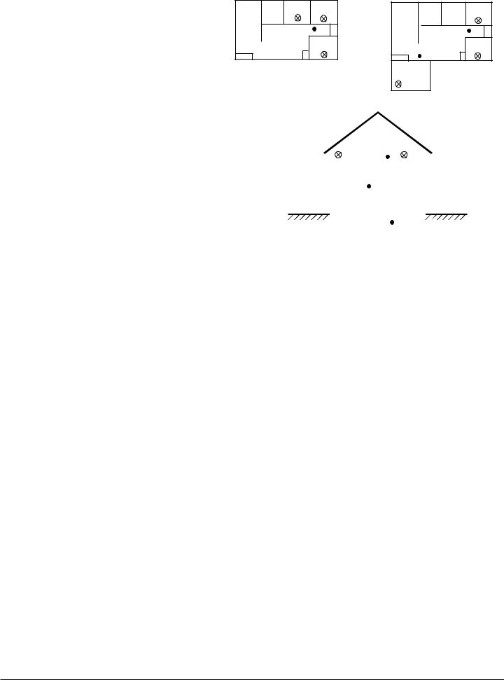
Required smoke alarms
Additional alarms required for new construction
1 Dining Room
2 Kitchen
3 Living Room
4 Bedroom
5 TV Room
6 Basement
A |
|
|
|
1 |
2 |
4 |
4 |
|
3 |
|
4 |
|
|
|
C
B |
|
|
|
5 |
1 |
2 |
4 |
|
3 |
|
4 |
|
|
|
|
4 |
|
|
|
|
Détecteurs de fumée requis |
|
|
|
|
|
|
|
|
|
|
|
|
|
|
|
|
|
|
|
|
|
|
|
|
|
Détecteurs supplémentaires nécessaires |
|
|
|
|
|
|
|
|
|
|
|
|
dans les nouvelles pièces |
4 |
4 |
|
||||||||
1 |
Salle à manger |
|
||||||||||
|
|
|
|
|
|
|
|
|
|
|
||
2 |
Cuisine |
|
|
|
|
|
|
|
|
|
|
|
|
|
|
|
|
|
|
|
|
|
|
||
3 |
|
|
|
|
|
1 |
|
|||||
3 |
Salle de séjour |
|
|
|
|
|
||||||
|
|
|
|
|
|
|||||||
4 |
Chambre à coucher |
|
|
|
|
|
|
|
|
|
|
|
|
|
|
|
|
|
|
|
|
|
|
||
|
|
|
|
|
|
|
|
|
|
|
||
5 |
Salle de télévision |
6 |
|
|
|
|
|
|
|
|
||
|
|
|
|
|
|
|
|
|||||
|
|
|
|
|
|
|
|
|||||
6 |
|
|
|
|
|
|
|
|
|
|||
Sous-sol |
|
|
|
|
|
|
|
|
|
|
|
|
|
|
|
|
|
|
|
|
|
|
|
||
|
|
|
|
|
|
|
|
|
|
|
|
|
Description
The ESL supervised smoke alarms are self-diagnostic Learn Mode wireless sensors with 319.5 MHz transmitters that use photoelectric technology with a self contained sounder, a low battery annunciator, status LED, and integrated fixed temperature and rate-of-rise heat sensor. Each unit has a base tamper switch, is part of a residential security/fire alarm system, and communicates with the system control panel.
Transmitted Signal Outputs
•Alarm |
•Tamper |
•Test |
•Low battery |
•Trouble |
•Supervisory |
Programming
This section describes the basic steps for programming (learning) the unit into panel memory. For complete programming instructions, refer to the specific panel installation instructions.
1. Separate the unit from the mounting base by turning the unit counter clockwise about 15 degrees.
2. Slide the battery cover away from the unit to unsnap it and lift it off. See Figure 2.
3. Observing polarity, insert the 2 lithium batteries (included) into the battery compartment and replace the battery cover.
4. Attach the unit to the mounting base by lining up the alignment tab (see Figure 3) on the unit with the alignment arrow on the mounting base, then put the unit on the base and turn it clockwise about 15 degrees. The unit should snap into place.
5. Put the panel into installer programming mode (refer to your panel installation instructions) and proceed to learning/enrolling sensors.
6. When prompted by the panel to learn/enroll the sensor, trip the tamper by separating the unit from the mounting base. See Step 1.
7. Attach the unit to the mounting base. See Step 4.
8. Exit from installer programming mode.
Verify Programming and Unit-to-Panel RF Communication
Before mounting, verify that the desired unit location provides good RF communication to the panel.
1. Put the panel into Dealer Sensor Test mode (refer to the specific panel installation instructions).
2. Take the unit to the desired mounting location.
3. Press and hold the unit Test/Silence button for 4 seconds. The unit transmits a test signal.
4. Listen for the appropriate response from system sirens to determine signal integrity from the unit to the panel (refer to the specific panel installation instructions).
5. Exit from Dealer Sensor Test mode.
Mounting
Mounting hardware is included (screws and anchors), however you may need different hardware depending on the installation.
1. Separate the unit from the mounting base. See Programming Step 1.
2. Place the mounting base on the mounting surface at the desired location and mark the mounting holes using a pencil.
3. Secure the mounting base to the surface.
4. Attach the unit to the mounting base. See Programming Step 4.
Sensor Test
The system and sensor test verifies good communication between the unit and receiver/panel. The sensor test should be performed weekly.
1. Put the panel into Sensor Test mode (refer to the specific panel installation instructions).
2. Press and hold the Test/Silence button for 4 seconds. The unit transmits a test signal.*
*Holding the Test/Silence button for 20 seconds will cause the unit to send a signal through to a central station.
3. Listen for the appropriate response from system sirens (refer to the specific panel installation instructions).
4. After testing all units, exit from Sensor Test mode.
Smoke Test
The smoke test verifies that the unit activates when detecting smoke, that the transmitted signal is received by the receiver/panel, and that the panel reports the alarm to the central monitoring station. The smoke test should be performed annually.
1. Contact the central monitoring station to alert them you are testing the system and they should not dispatch authorities.
2. Activate the unit using one of the following two methods:
Method 1 Hold a smoldering punk or cotton wick close to the unit and direct the smoke into the smoke entry openings for about 20 seconds.
Method 2 Use Smoke! in a can® and follow the directions on the can.
Once activated, the transmitter LED turns on, the built-in sounder emits a temporal 3 pattern, and the unit transmits an alarm signal. The panel then processes the alarm signal and reports the alarm condition to the central station.
2 |
TX-6010-01-1 |

3. Press the Test/Silence button to quiet the sounder. The unit automatically resets when smoke is no longer present and the LED should turn off and return to normal operation (one flash every 9 seconds).
4. Contact the central monitoring to verify they received the alarm report.
5. Alert the central monitoring station when you are finished testing.
Sensitivity Test
1. Press and hold the test/silence button for two seconds, then release it. The unit transmits a test signal, then performs a self-test that causes the LED to flash 1 to 9 times.
2. Count the number of LED flashes, then use the following table to determine if any action is necessary.
Flashes
0-1 |
Indication: |
Unservicable hardware fault. |
|
Action: |
Reset and rerun sensitivity test. If the error |
|
|
persists, replace unit. |
|
|
|
2-3 |
Indication: |
Unit is becoming insensitive. |
|
Action: |
Clean and reset the unit. Rerun sensitivity test. |
|
|
If the error persists, replace the unit. |
|
|
|
4-7 |
Indication: |
Unit is within normal sensitivity range. |
|
Action: |
N/A |
|
|
|
8-9 |
Indication: |
Unit is becoming too sensitive. |
|
Action: |
Verify the optical chamber is snapped down |
|
|
securely. Clean the unit and replace the optical |
|
|
chamber. |
|
|
|
After the LED flashes, if the sensitivity is within limits and all other tests pass, the unit goes into alarm and resets after 7 seconds. If the sensitivity is not within limits, or an unserviceable hardware fault has been detected, the unit LED extinguishes until the unit is serviced.
Troubleshooting
The following describes how the unit indicates a fault condition. Correct fault conditions as soon as possible.
•The LED stops working (no flashing or turning on), see Sensitivity Test.
•The unit stops transmitting supervisory signals if the unit has an unserviceable hardware fault or is not sensitive enough, causing the panel to indicate the detector is in a supervisory condition. However, the unit can still transmit alarm signals.
•The unit transmits a trouble (CleanMe) signal, see Maintaining the Units.
When to Replace the Batteries
When the battery voltage gets low, the unit transmits a low battery signal for the panel to receive. The panel activates trouble beeps through system sirens and identifies the unit with the low battery on system touchpad displays. If the batteries are not replaced within seven days, the unit’s built-in sounder emits a short beep or chirp every 45 seconds. Unit chirps can be silenced for 24 hours by pressing the Test/Silence button. Batteries should be replaced as soon as possible.
Replacing the Batteries
Use only 3V lithium batteries listed in Specifications.
1. Remove the unit from the mounting base. See Programming Step 1.
2. Slide the battery compartment cover away from the alarm to unsnap it and lift it off. See Figure 2.
3. Remove the batteries and dispose of them properly.
4. Observing correct polarity, insert two new 3V lithium batteries into the battery compartment and replace the cover.
5. Reattach the unit to the mounting base. See Programming Step 4.
6. Test the system.
Cleaning
Clean the cover with a dry or damp (water) cloth as needed to keep it free from dust and dirt.
When necessary, clean the interior and replace the optical chamber (part #211) as follows:
1. Disconnect the alarm notification appliances.
2. Remove the unit from the mounting base. See Programming Step 1.
3. Remove the batteries. See Replacing the Batteries.
4. Slide a flat-blade screwdriver in the slot on the alarm cap and gently push the handle down to pry the alarm cap up and off. See Figure 4.
5. Squeeze the optical chamber where indicated and pull it up and away from the optical base and discard. See Figure 5.
6. Blow out or use a soft-bristled brush to remove all dust and dirt from the optical base.
7. Line the new optical chamber up with the optical base and snap into place both sides of the optical chamber.
8. Replace the alarm cap as follows:
-Line the alarm cap up with the unit.
-Insert the alarm cap into the unit and turn clockwise approximately 15 degrees. It should snap firmly into place.
9. Observing the proper polarity, replace the batteries and the battery compartment cover.
10.Reattach the unit to the mounting base. See Programming Step 4.
11. Test the sensitivity and reconnect all alarm notification appliances. See Sensitivity Test.
Important !
The control panel alarm and all auxiliary functions should be verified for a complete test of the system.
Maintenance
The units are designed for easy field service and maintenance. When installed and used properly, they require minimal maintenance.
The units should be tested weekly.
When a unit requires maintenance, it extinguishes its LED and sends a signal to the control panel as described in the following table.
Signal |
Action Required |
Trouble Signal |
Sensitivity range is too high and the unit needs |
|
cleaning. See Cleaning. Panels supporting this |
|
feature identify the trouble as “Partial Obscurity” |
|
on system touchpad displays. |
|
|
Low Battery |
Batteries in the unit are low. Replace the batteries. |
Specifications
Voltage |
3VDC |
Typical average standby current |
35µA |
Typical test current |
2mA |
Typical alarm current |
70mA |
Battery type |
3V lithium, Duracell® 123,Panasonic® |
|
CR123A, Sanyo® CR123A |
Low battery threshold |
2.70V causes low battery signal |
Sounder |
85dBa at 10' temporal pattern |
Low battery beep rate |
1 every 45 sec. |
Sensitivity |
2.2% ± 1.3% / ft. |
Operating temperature |
40°-100°F (4.4°-37.8°C) |
Operating humidity range |
0-95% non-condensing |
Color |
white |
Alarm dimensions |
5.6" x 2.4" (14.2cm x 6.1cm) |
Base dimensions |
5.4" x 0.46" (13.7cm x 1.17cm) |
Drift compensation adjustment |
0.5% / ft. max. |
Heat detector specifications: |
|
Rate-of-rise |
15°F/min>105°F (8.3°C/min>40.6°C) |
Fixed |
135°F ± 5°F (57.2°C ± 2.8°C) |
RFI Immunity |
20V/m minimum; 0-1000MHz |
RF frequency |
319.5 MHz |
Transmitter ID |
Pre-programmed, 1 Million codes |
Modulation type |
AM |
Signal format |
PWM |
Signal output types |
alarm, tamper, test, low battery, |
|
trouble, supervisory |
Listings |
UL217, C-UL US, CSFM, FCC |
TX-6010-01-1 |
3 |
 Loading...