


957C
www.reelschematic.com
www.reelschematic.com

Thank You!
Thank you for choosing Humminbird®, America's #1 name in fishfinders. Humminbird® has built its reputation by designing and manufacturing top-quality,
thoroughly reliable marine equipment. Your Humminbird® is designed for trouble-free use in even the harshest marine environment. In the unlikely event that
your Humminbird® does require repairs, we offer an exclusive Service Policy - free of charge during the first year after purchase, and available at a reasonable
rate after the one-year period. For complete details, see the Warranty section in this manual. We encourage you to read this installation and operations manual
carefully in order to get full benefit from all the features and applications of your Humminbird® product.
Contact our Customer Resource Center at either 1-800-633-1468 or visit our website at www.humminbird.com.
WARNING! This device should not be used as a navigational aid to prevent collision, grounding, boat damage, or personal injury. When the boat is moving, water depth may
change too quickly to allow time for you to react. Always operate the boat at very slow speeds if you suspect shallow water or submerged objects.
WARNING! Disassembly and repair of this electronic unit should only be performed by authorized service personnel. Any modification of the serial number or attempt to repair
the original equipment or accessories by unauthorized individuals will void the warranty. Handling and/or opening this unit may result in exposure to lead, in the form of solder.
WARNING! This product contains lead, a chemical known to the state of California to cause cancer, birth defects and other reproductive harm.
NOTE: Some features discussed in this manual require a separate purchase, and some features are only available on international models. Every effort has been made to clearly
identify those features. Please read the manual carefully in order to understand the full capabilities of your model.
900 Series™, Cannon™, CannonLink™, DualBeam PLUS™, Fish ID+™, HumminbirdPC™, Humminbird®, InterLink™, One-Touch® Zoom, QuadraBeam PLUS™, RTS® Window, SmartCast®, Structure ID®, Total Screen
Update®, TrueArch®, WeatherSense®, WhiteLine®, WideSide®, X-Press™, and X-Press™ Menu are trademarked by or registered trademarks of Humminbird®.
© 2007 Humminbird®, Eufaula AL, USA. All rights reserved.
i
www.reelschematic.com
www.reelschematic.com

Table of Contents
ii
900 Series™ Introduction 1
How Sonar Works .......................................................................................................... 1
DualBeam PLUS™ Sonar .............................................................................................. 2
QuadraBeam PLUS™ Sonar
(Standard with 957c Combo models, optional-purchase for 917c Combo models only) ........ 3
Universal Sonar 2 ............................................................................................................ 3
How GPS and Cartography Work .................................................................................. 3
Multi-Media Card (MMC)/SD Slot.................................................................................. 5
Software Updates............................................................................................................ 5
Accessory Bus .................................................................................................................. 5
Installation Overview 5
Control Head Installation 6
Gimbal Mounting the Control Head .............................................................................. 7
Connecting the Control Head Power Cable to the Boat ............................................ 11
Transducer Installation 12
Transom Transducer Installation .................................................................................. 13
Inside the Hull Transducer Installation ...................................................................... 21
Trolling Motor Transducer Installation ........................................................................ 24
Trolling Motor Transducer Options .............................................................................. 25
GPS Receiver Installation 25
Stem Mounting with an Existing 1" - 14 Thread Stem .............................................. 26
Access Under Mounting Location................................................................................ 27
No Access Under Mounting Location.......................................................................... 27
Finish Routing the Cable and Check GPS Receiver Operation .................................. 28
Testing the System Installation 29
Getting Started - Using Your 900 Series™ 30
Powering Up the Control Head .................................................................................... 30
What’s on the Sonar Display ...................................................................................... 31
Understanding Sonar History ...................................................................................... 32
Real Time Sonar (RTS®) Window.................................................................................. 32
Bottom Presentation...................................................................................................... 32
Key Functions 33
POWER/LIGHT Key ........................................................................................................ 33
VIEW Key........................................................................................................................34
MENU Key...................................................................................................................... 34
4-WAY Cursor Control Key ............................................................................................ 35
View Preset Keys............................................................................................................ 35
EXIT Key.......................................................................................................................... 35
INFO Key ........................................................................................................................36
MARK Key ...................................................................................................................... 36
GOTO Key........................................................................................................................ 36
ZOOM (+/-) Keys............................................................................................................ 37
531553-1_B
www.reelschematic.com
www.reelschematic.com

Table of Contents
iii
Views 37
Views and Readouts...................................................................................................... 37
Sonar View .................................................................................................................... 38
Sonar Zoom View .......................................................................................................... 39
Split Sonar View ............................................................................................................ 40
Snapshot and Recording View...................................................................................... 41
Side Beam View
(with QuadraBeam PLUS™ only)
.......................................................... 45
Bird’s Eye View .............................................................................................................. 47
Chart/Bird’s Eye Combo View ...................................................................................... 48
Chart/Chart Combo View.............................................................................................. 49
Chart View......................................................................................................................50
Chart/Sonar Combo View.............................................................................................. 51
Chart Orientation .......................................................................................................... 52
Viewing Cartography 52
Navigation 53
Waypoints, Routes and Tracks...................................................................................... 54
Save, Edit, or Delete a Waypoint.................................................................................. 55
Navigate to a Waypoint or Position.............................................................................. 56
Add a Waypoint Target or Trolling Grid........................................................................ 56
Save, Edit or Delete a Route ........................................................................................ 57
Save or Clear a Current Track ...................................................................................... 58
Edit, Delete or Hide Saved Tracks ................................................................................ 58
Man Overboard (MOB) Navigation .............................................................................. 59
The Menu System 60
Start-Up Options Menu 61
Normal Operation .......................................................................................................... 62
Simulator ......................................................................................................................62
System Status .............................................................................................................. 62
Self Test.......................................................................................................................... 63
Accessory Test................................................................................................................ 63
GPS Diagnostic View .................................................................................................... 64
Sonar X-Press™ Menu 65
Active Side...................................................................................................................... 65
Split Position ..................................................................................................................66
Sensitivity ...................................................................................................................... 66
Upper Range
(Advanced: Sonar, Split Sonar and Active Sonar Side Views only) ....................................
67
Lower Range ................................................................................................................ 67
Chart Speed .................................................................................................................. 68
Quad Layout
(with QuadraBeam PLUS™ Transducer, Side Beam View only)
...................................... 68
Bottom Lock
(Sonar Zoom View only)
............................................................................ 69
Bottom Range
(Sonar Zoom View only, when Bottom Lock is on)
.................................... 69
Sonar Colors .................................................................................................................. 69
Cancel Navigation
(only when navigating)
...................................................................... 69
www.reelschematic.com
www.reelschematic.com
Table of Contents
iv
Navigation X-Press™ Menu 70
Active Side...................................................................................................................... 70
Split Position ..................................................................................................................70
Waypoint [Name]
(Only with an active cursor on a waypoint) ............................................ 71
Cursor to Waypoint
(Chart or Combo view only) .................................................................. 71
Save Current Track ........................................................................................................ 72
Clear Current Track ........................................................................................................ 72
Save Current Route
(Only when navigating)
.................................................................. 72
Skip Next Waypoint
(Only when navigating)
.................................................................. 72
Cancel Navigation
(Only when navigating)
.................................................................... 73
Cancel MOB Navigation
(only when MOB Navigation is activated)
................................ 73
Remove Target
(Only if a Target is active)
........................................................................ 73
Remove Grid
(Only if a Grid is active)
.............................................................................. 73
Waypoint Name
(Most recently-created waypoint)
.......................................................... 74
Snapshot and Recording X-Press™ Menu
(Snapshot and Recording View only)
75
Start Recording
(optional-purchase MMC/SD Card, Snapshot and Recording View only)..........................
75
Stop Recording
(optional-purchase MMC/SD Card only) ......................................................
75
Delete Image
(optional-purchase MMC/SD Card, Snapshot and Recording View only)..........................
76
Delete All Images
(optional-purchase MMC/SD Card, Snapshot and Recording View only)..........................
76
Delete Recording
(optional-purchase MMC/SD Card, Snapshot and Recording View only)..........................
77
Delete All Recordings
(optional-purchase MMC/SD Card, Snapshot and Recording View only)..........................
77
Pings Per Second
(optional-purchase MMC/SD Card, Snapshot and Recording View only)..........................
78
Playback Speed
(optional-purchase MMC/SD Card, Snapshot and Recording View only)..........................
78
Stop Playback
(optional-purchase MMC/SD Card only) ........................................................
79
Sonar Menu Tab 79
Beam Select .................................................................................................................. 80
Fish ID+™ ...................................................................................................................... 80
Fish ID Sensitivity .......................................................................................................... 81
Real Time Sonar (RTS®) Window.................................................................................. 82
Bottom View .................................................................................................................. 82
Zoom Width
(Sonar Zoom View only)
.............................................................................. 82
83 kHz Sensitivity .......................................................................................................... 83
455 kHz Sensitivity
(Advanced, with QuadraBeam PLUS™ transducer, optional-purchase for the 917) ........
83
Depth Lines
(Advanced)
.................................................................................................. 84
Surface Clutter
(Advanced)
............................................................................................ 84
Noise Filter
(Advanced)
.................................................................................................... 85
Max Depth
(Advanced)
.................................................................................................... 85
Water Type
(Advanced)
.................................................................................................. 86
Transducer Select .......................................................................................................... 86
Color Bar ........................................................................................................................ 86
Temperature
(Sonar View only, with Temperature input)
................................................ 87
www.reelschematic.com
www.reelschematic.com

Table of Contents
v
Navigation Menu Tab 87
Current Track .................................................................................................................. 88
Saved Tracks .................................................................................................................. 88
Waypoints ...................................................................................................................... 89
Routes ............................................................................................................................ 89
Chart Orientation .......................................................................................................... 90
North Reference ............................................................................................................ 90
Trolling Grid Rotation .................................................................................................... 91
Trackpoint Interval.......................................................................................................... 91
Track Min Distance
(Advanced)
...................................................................................... 91
Track Color Range.......................................................................................................... 92
Map Datum
(Advanced)
.................................................................................................. 92
Course Projection Line .................................................................................................. 92
Export All Nav Data
(Advanced)
.................................................................................... 92
Delete All Nav Data
(Advanced)
.................................................................................... 93
Continuous Navigation Mode ...................................................................................... 93
Chart Menu Tab 93
Chart Detail Level .......................................................................................................... 94
Map Borders .................................................................................................................. 94
Lat/Lon Grid....................................................................................................................95
Spot Soundings.............................................................................................................. 95
Navaids on Bird's Eye View .......................................................................................... 95
Shaded Depth ................................................................................................................ 95
Set Simulation Position
(Advanced)
.............................................................................. 96
Set Map Offset
(Advanced)
............................................................................................ 96
Clear Map Offset
(Advanced)
.......................................................................................... 97
Alarms Menu Tab 97
Depth Alarm .................................................................................................................. 98
Fish ID Alarm.................................................................................................................. 98
Low Battery Alarm ........................................................................................................ 98
Aux Temp Alarm
(with optional-purchase temp. probe or Temp/Speed only)......................
99
Temp Alarm.................................................................................................................... 99
Off Course Alarm ........................................................................................................ 100
Arrival Alarm ................................................................................................................ 100
Drift Alarm.................................................................................................................... 101
Alarm Tone .................................................................................................................. 101
Setup Menu Tab 102
Units - Depth................................................................................................................ 102
Units - Temp
(International only)
.................................................................................... 102
Units - Distance
(with Speed input only)
...................................................................... 103
Units - Speed
(with Speed input only)
.......................................................................... 103
User Mode.................................................................................................................... 103
Language
(International only)
........................................................................................ 103
Triplog Reset
(with Speed input only)
............................................................................ 104
Restore Defaults .......................................................................................................... 104
Select Readouts
(Advanced)
........................................................................................ 104
www.reelschematic.com
www.reelschematic.com

Table of Contents
vi
Depth Offset
(Advanced)
.............................................................................................. 106
Aux. Temp. Offset
(Advanced)
...................................................................................... 106
Temp Offset
(Advanced)
................................................................................................ 106
Speed Calibration
(Advanced, with Speed paddlewheel only)
...................................... 107
Local Time Zone
(Advanced)
........................................................................................ 107
Daylight Saving Time
(Advanced)
................................................................................ 107
Position Format
(Advanced)
.......................................................................................... 107
Time Format
(Advanced, International only)
.................................................................. 108
Date Format
(Advanced, International only)
.................................................................. 108
Digits Format
(Advanced) ......................................................................................................
109
NMEA Output
(Advanced)
............................................................................................ 109
Sonar ............................................................................................................................ 110
Views Menu Tab 110
Accessories Menu Tab 112
Using Screen Snapshot .............................................................................................. 112
Troubleshooting 114
900 Series™ Doesn’t Power Up.................................................................................. 114
900 Series™ Defaults to Simulator with a Transducer Attached ............................ 114
Display Problems 115
Finding the Cause of Noise 116
1-Year Limited Warranty 117
Humminbird® Service Policy 117
900 Series™ Accessories 119
Specifications 121
Glossary 122
Contact Humminbird® 133
NOTE: Entries in this Table of Contents which list (International only) are only
available on products sold outside of the US and Canada by our authorized
International Distributors. To obtain a list of authorized International Distributors,
please visit our website at www.humminbird.com or contact our Customer
Resource Center at 1-800-633-1468 to locate the distributor nearest you.
NOTE: Entries in this Table of Contents which list (with Speed Input) or (with
Temperature Input) may require the purchase of separate accessories. You can
visit our website at www.humminbird.com to order these accessories online or
contact our Customer Resource Center at 1-800-633-1468.
www.reelschematic.com
www.reelschematic.com

www.reelschematic.com
www.reelschematic.com
900 Series™ Introduction
Your 900 Series™ Ultra Wide Screen Fishing System comes in several
different configurations. See the following list of products, all of which are
covered by this manual, to find your 900 Series™ configuration:
• Humminbird® 917c Combo: Ultra Wide Screen Fishing System with
Chartplotter (Maps) and DualBeam PLUS™ 200/83 kHz Transducer,
GPS Receiver included
• Humminbird® 957c Combo: Ultra Wide Screen Fishing System with
Chartplotter (Maps) and QuadraBeam PLUS™ 200/83/455 kHz
Transducer, GPS Receiver included.
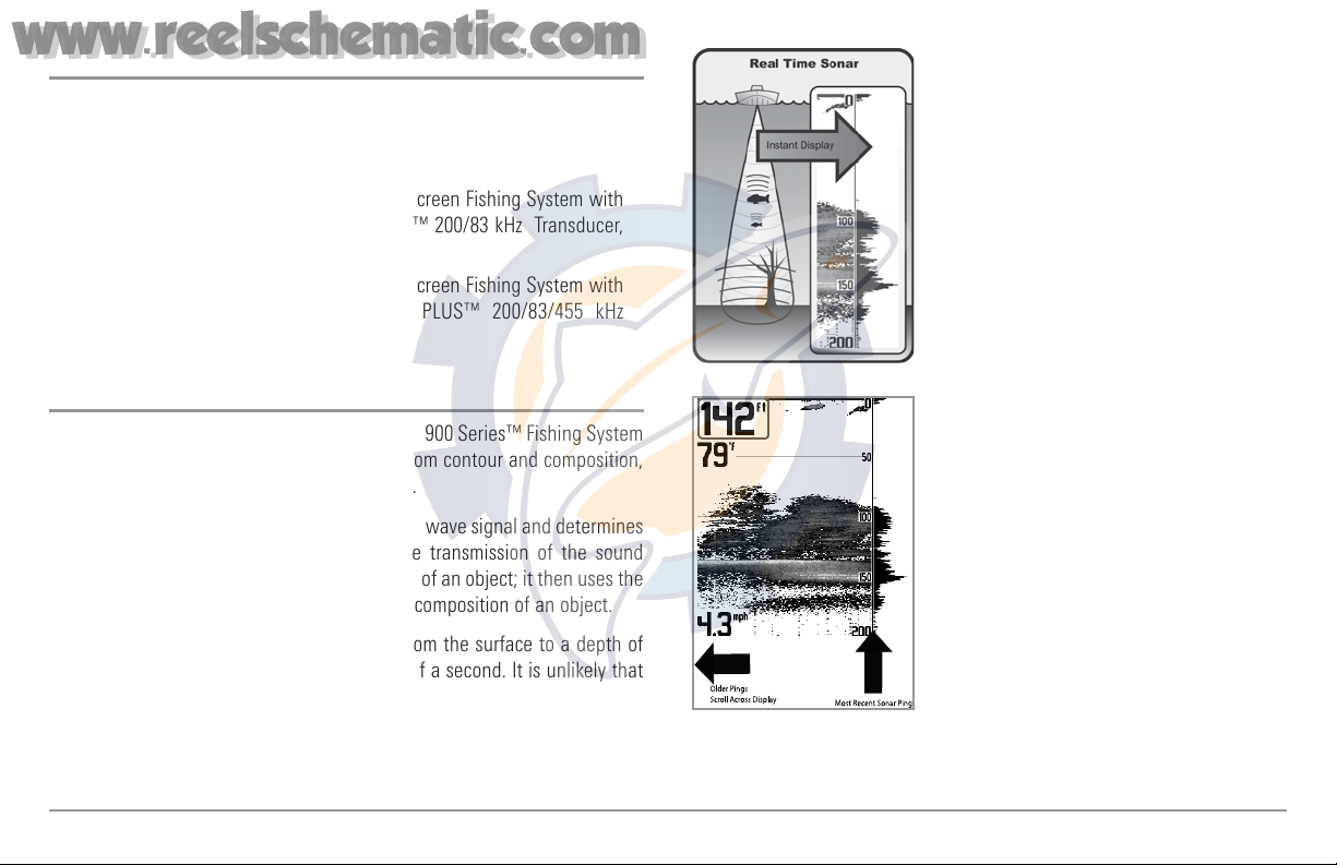
How Sonar Works
Sonar technology is based on sound waves. The 900 Series™ Fishing System
uses sonar to locate and define structure, bottom contour and composition,
as well as depth directly below the transducer.
Your 900 Series™ Fishing System sends a sound wave signal and determines
distance by measuring the time between the transmission of the sound
wave and when the sound wave is reflected off of an object; it then uses the
reflected signal to interpret location, size, and composition of an object.
Sonar is very fast. A sound wave can travel from the surface to a depth of
240 ft (70 m) and back again in less than 1/4 of a second. It is unlikely that
your boat can "outrun" this sonar signal.
SONAR is an acronym for SOund and
NAvigation Ranging. Sonar utilizes precision
sound pulses or "pings" which are emitted into
the water in a teardrop-shaped beam.
The sound pulses "echo" back from objects in
the water such as the bottom, fish and other
submerged objects. The returned echoes are
displayed on the LCD screen. Each time a new
echo is received, the old echoes are moved
across the LCD, creating a scrolling effect.
When all the echoes are viewed side by side,
an easy to interpret "graph" of the bottom, fish
and structure appears.
1
www.reelschematic.com
www.reelschematic.com

The sound pulses are transmitted at various
frequencies depending on the application.
Very high frequencies (455 kHz) are used for
greatest definition but the operating depth is
limited. High frequencies (200 kHz) are
commonly used on consumer sonar and
provide a good balance between depth
performance and resolution. Low frequencies
(83 kHz) are typically used to achieve greater
depth capability.
The power output is the amount of energy
generated by the sonar transmitter. It is
commonly measured using two methods:
• Root Mean Square (RMS) measures power
output over the entire transmit cycle.
• Peak to Peak measures power output at the
highest points.
The benefits of increased power output are
the ability to detect smaller targets at greater
distances, ability to overcome noise, better
high speed performance and enhanced depth
capability.
DualBeam PLUS™ Sonar
Your 900 Series™ Fishing System uses a
200/83 kHz DualBeam PLUS™ sonar system
with a wide (60°) area of coverage.
DualBeam PLUS™ sonar has a narrowly
focused 20° center beam, surrounded by a
second beam of 60°, expanding your
coverage to an area equal to your depth.
In 20 feet of water, the wider beam covers
an area 20 feet wide. The 20° center beam is
focused on the bottom, to show you
structure, weeds and cover. The 60° wide
beam is hunting for fish in the wide
coverage area. DualBeam PLUS™ sonar
returns can be blended together, viewed
separately or compared side-by-side.
DualBeam PLUS™ is ideal for a wide range
of conditions - from shallow to very deep
water in both fresh and salt water. Depth
capability is affected by such factors as boat
speed, wave action, bottom hardness, water
conditions and transducer installation.
2
www.reelschematic.com
www.reelschematic.com
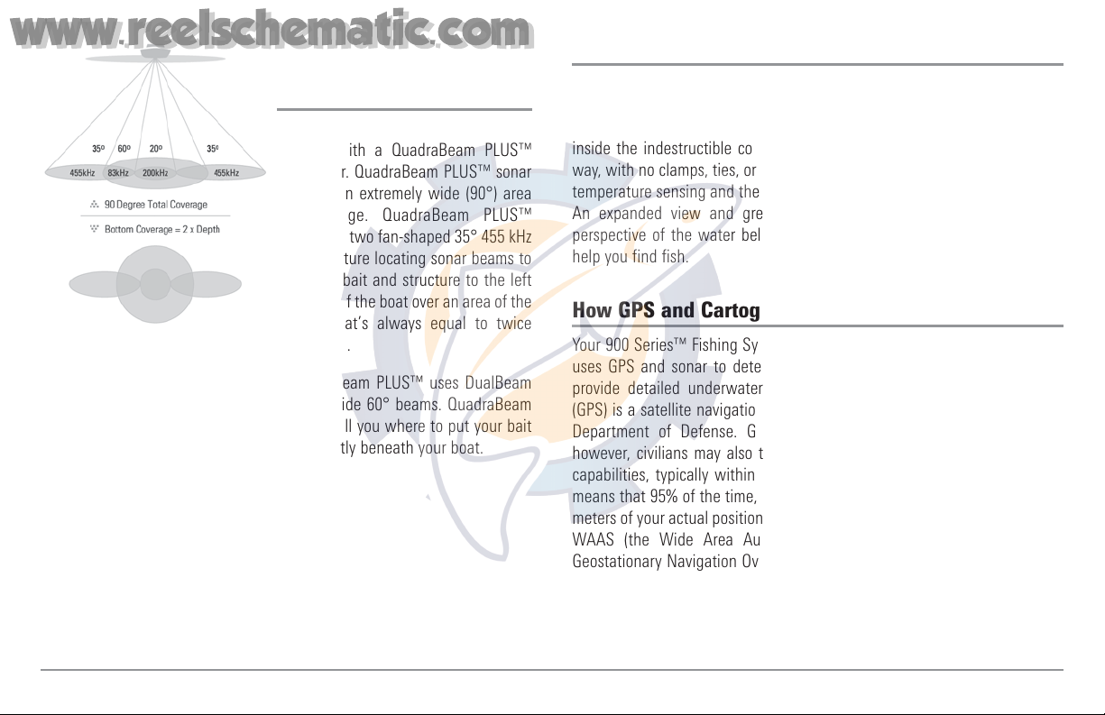
QuadraBeam PLUS™ Sonar
(Standard with 957c Combo models, optional-
purchase for 917c Combo models only)
Your 900 Series™ 957c Combo is
shipped with a QuadraBeam PLUS™
transducer. QuadraBeam PLUS™ sonar
provides an extremely wide (90°) area
of coverage. QuadraBeam PLUS™
starts with two fan-shaped 35° 455 kHz
Side Structure locating sonar beams to
spot fish, bait and structure to the left
and right of the boat over an area of the
bottom that’s always equal to twice
your depth.
For a detailed view below the boat, QuadraBeam PLUS™ uses DualBeam
PLUS™ technology, with precision 20° and wide 60° beams. QuadraBeam
PLUS™ finds more fish faster, and can even tell you where to put your bait
by showing if fish are to the left, right or directly beneath your boat.
Universal Sonar 2
Your 900 Series™ Fishing System supports Universal Sonar 2, a state-of-the-
art, integrated and protected transducer that is built into the lower unit of
Minnkota trolling motors. With Universal Sonar 2, all wiring is concealed
inside the indestructible composite shaft—out of sight and out of harm’s
way, with no clamps, ties, or exposed wires. Universal Sonar 2 features new
temperature sensing and the performance of DualBeam PLUS™ technology.
An expanded view and greater bottom detail gives you a totally new
perspective of the water below, along with optimal sonar performance to
help you find fish.
How GPS and Cartography Work
Your 900 Series™ Fishing System also supports GPS and chartplotting, and
uses GPS and sonar to determine your position, display it on a grid, and
provide detailed underwater information. The Global Positioning System
(GPS) is a satellite navigation system designed and maintained by the U.S.
Department of Defense. GPS was originally intended for military use;
however, civilians may also take advantage of its highly accurate position
capabilities, typically within +/- 10 meters, depending on conditions. This
means that 95% of the time, the GPS receiver will read a location within 10
meters of your actual position. Your GPS Receiver also uses information from
WAAS (the Wide Area Augmentation System), EGNOS (the European
Geostationary Navigation Overlay Service), and MSAS (the MTSAT Satellite
Augmentation System) satellites if they are available in your area.
3
www.reelschematic.com
www.reelschematic.com

GPS uses a constellation of 24 satellites that
continually send radio signals to the earth.
Your present position is determined by
receiving signals from up to 16 satellites and
measuring the distance from the satellites.
All satellites broadcast a uniquely coded signal once per second at exactly the
same time. The GPS receiver on your boat receives signals from satellites that
are visible to it. Based on time differences between each received signal, the
GPS receiver determines its distance to each satellite. With distances known,
the GPS receiver mathematically triangulates its own position. With once per
second updates, the GPS receiver then calculates its velocity and bearing.
The GPS Receiver included with your 900 Series™ Fishing System allows you
to combine easy-to-use FishingGPS® chartplotter and navigation capabilities
with advanced fishfinding.
The following GPS functionality is currently supported by the 900 Series™
Fishing System when it is connected to the included GPS receiver:
• View current position
• View current track (breadcrumb trail)
• View precision speed and heading from your GPS receiver
• Save tracks, waypoints and routes
• Travel a route and navigate from one waypoint to the next.
Your 900 Series™ supports Navionics® Gold, HotMaps™ and HotMaps™
Premium on MMC or SD card media.
NOTE: Your 900 Series™ does not support Navionics® Classic Charts, only
Navionics® Gold, HotMaps™, and HotMaps™ Premium.
Your unit also comes with a built-in UniMap™ with a more detailed map of
North America (Domestic models) or a more detailed map of Europe and
Southeast Asia, including Australia and New Zealand (International models).
Your 900 Series™ uses the GPS Receiver to determine the position of the
boat automatically, and uses the zoom level settings on a particular view to
select the best chart to display. See Viewing Cartography for more
information.
4
www.reelschematic.com
www.reelschematic.com
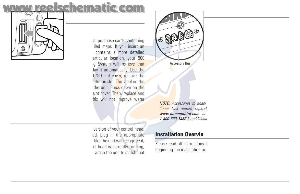
Multi-Media Card
(MMC)/SD Slot
Your 900 Series™ Fishing System also has a
multi-media card (MMC)/SD slot that is used
to insert optional-purchase cards containing
additional detailed maps. If you insert an
MMC/SD that contains a more detailed
chart for a particular location, your 900
Series™ Fishing System will retrieve that
chart and display it automatically. Use the
illustration to locate the position of the MMC/SD slot cover, remove the
MMC/SD slot cover, then insert the MMC/SD into the slot. The label on the
MMC/SD should face toward the left side of the unit. Press down on the
card until it clicks into place and replace the slot cover. Then, replace and
tighten snugly - do NOT overtighten, as this will not improve water
resistance, and may damage the cover.
Software Updates
Use the MMC/SD slot to update the software version of your control head.
To update the software in your control head, plug in the appropriate
MMC/SD card that contains a software update file; the unit will recognize it,
will tell you what software version your control head is currently running,
and will ask you if you want to update the software in the unit to match that
on the MMC/SD card. You can obtain software updates from the
www.humminbird.com website.
Accessory Bus
Use the Accessory Bus to expand the
functionality of your 900 Series™. Accessories
plug directly into the 900 Series™, enabling
Advanced features such as WeatherSense®
and the SmartCast® Wireless Sonar Link.
Additional tabs and menu choices will be
added to the menu system automatically when
an accessory is plugged into the unit. In
addition, multiple accessories can be attached
simultaneously. See Accessories Menu Tab
and 900 Series™ Accessories in this manual,
as well as your accessory Operations Manual
for additional details.
NOTE: Accessories to enable WeatherSense® and the SmartCast® Wireless
Sonar Link require separate purchases. You can visit our website at
www.humminbird.com or contact our Customer Resource Center at
1-800-633-1468 for additional details.
Installation Overview
Please read all instructions that are relevant for your configuration before
beginning the installation process.
NOTE: Installation procedures will depend on product configuration.
Accessory Bus
Inserting an MMC/SD
into the Card Slot
5
www.reelschematic.com
www.reelschematic.com

Inside the boat there is often a channel or conduit used for other wiring, this
can be used to route cables. Be sure to route the cable as far as practical
from the antenna cable of VHF radios or tachometer cables to reduce the
possibility of interference. The transducer and GPS receiver cables should
not be cut, and care should be used not to damage the cable insulation.
Basic installation tasks that you must perform include:
• Installing the control head (choosing either gimbal or in-dash
mounting, where in-dash mounting requires a separate purchase)
• Installing the transducer (choosing either the transom mount,
inside the hull mount, or trolling motor mounting method)
• Installing the GPS Receiver (if included)
• Testing the complete installation and locking the transducer position.
NOTE: Accessories may require a separate purchase. You can visit our website at
www.humminbird.com to order these accessories online or contact our
Customer Resource Center at 1-800-633-1468.
Control Head Installation
You have two choices for mounting your 900 Series™ control head, Gimbal
mounting, where you use a surface on the boat, such as the dash, to mount
the control head so that it can be tilted up or down, or In-dash mounting,
which requires a separate purchase.
The 900 Series™ has a wide variety of configurations.
Sonar Transducer w/Temperature
1
Optional “Y” Cable
2
Power
3
Speed through water
GPS Receiver
WeatherSense®
5
6
7
Temperature/Speed
4
SmartCast® Wireless Sonar Link
8
Accessory Bus
1
2
3
4
5
6
7
8
6
www.reelschematic.com
www.reelschematic.com
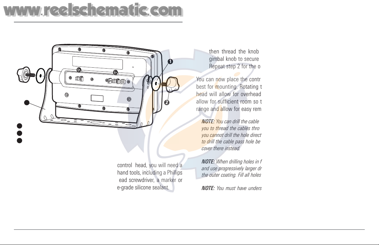
Gimbal Mounting the Control Head
If you are gimbal mounting the Humminbird® 900 Series™, you can pre-
assemble the unit in order to plan the best mounting location.
In addition to the hardware supplied with your control head, you will need a
powered hand drill and various drill bits, various hand tools, including a Phillips
head screwdriver, a socket wrench and a flat head screwdriver, a marker or
pencil, safety glasses and dust mask, and marine-grade silicone sealant.
1. Place the control head into the gimbal bracket. Make sure that the
straight side of the gimbal arm is against the back side of the control
head.
2. Place a 1" (25 mm) diameter black washer on the gimbal knob and
then thread the knob and washer into the housing. Tighten the
gimbal knob to secure the 900 Series™ control head to the mount.
Repeat step 2 for the other side.
You can now place the control head in various locations to decide which is
best for mounting. Rotating the mounting bracket to the top of the control
head will allow for overhead mounting. The chosen mounting area should
allow for sufficient room so the control head can pivot through the full tilt
range and allow for easy removal and installation.
NOTE: You can drill the cable pass hole underneath the gimbal bracket, allowing
you to thread the cables through the knock-out holes in the mount; however, if
you cannot drill the hole directly under the mounting bracket, then you will need
to drill the cable pass hole behind the bracket, and will need to mount the hole
cover there instead.
NOTE: When drilling holes in fiberglass hulls, it is best to start with a smaller bit
and use progressively larger drill bits to reduce the chance of chipping or flaking
the outer coating. Fill all holes with marine grade silicone sealant.
NOTE: You must have underside access to the mounting location to pass the
cables through to the surface. Also, make sure that the mounting surface is
adequately supported to protect the control head from excessive wave shock and
vibration and provide visibility while in operation.
Washer
1
Gimbal Knob
2
Gimbal Bracket
3
1
2
3
7
www.reelschematic.com
www.reelschematic.com
3. After the mounting location has been determined, loosen the gimbal
knobs and remove the control head from the gimbal bracket.
NOTE: Alternate hole patterns are available on the gimbal mounting bracket, and
may match existing holes on the boat. You may choose to use one of these
alternate hole patterns.
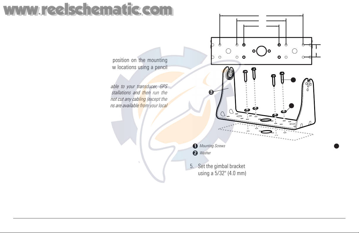
4. Place the gimbal bracket in the chosen position on the mounting
surface and mark the four mounting screw locations using a pencil
or center punch.
NOTE: Go to the installation instructions applicable to your transducer, GPS
Receiver and accessories. Make the required installations and then run the
cables to your control head mounting location. Do not cut any cabling (except the
power cable). If your cables are too short, extensions are available from your local
dealer or online from www.humminbird.com.
5. Set the gimbal bracket aside and drill the four mounting screw holes
using a 5/32" (4.0 mm) drill bit.
6a. If the cables must pass through a hole directly beneath the
mounting bracket, mark and drill an additional 1" (25 mm) hole
centered between the four mounting holes. Route the cables
through the 1" hole. Place the hole cover over the mounting surface
8.5"
5"
3.6"
1.25"
Mounting Screws
1
Washer
2
Gimbal Mounting Bracket
3
1
3
2
8
www.reelschematic.com
www.reelschematic.com
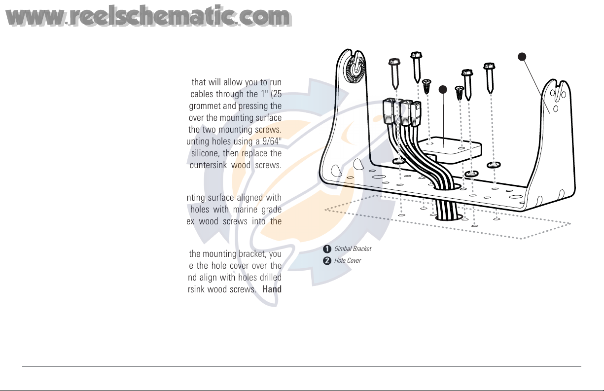
hole, then use it to mark the position of the two mounting screws.
Remove the hole cover, drill the two mounting holes using a 9/64"
bit. Do not install the hole cover at this time.
6b. If the cables cannot be routed directly beneath the mounting
bracket, mark and drill a 1" (25 mm) hole that will allow you to run
the cables close to the bracket. Pass the cables through the 1" (25
mm) hole, routing the cables through the grommet and pressing the
grommet into place. Place the hole cover over the mounting surface
hole, then use it to mark the position of the two mounting screws.
Remove the hole cover, drill the two mounting holes using a 9/64"
(3.5 mm) bit, fill them with marine-grade silicone, then replace the
hole cover and insert the #8 Phillips countersink wood screws.
Hand-tighten only.
7. Place the mounting bracket on the mounting surface aligned with
the drilled holes and fill the mounting holes with marine grade
silicone. Insert the four #10 Slotted-Hex wood screws into the
mounting holes. Hand-tighten only.
8. If the cable pass through hole is beneath the mounting bracket, you
will need to install the hole cover. Place the hole cover over the
mounting bracket cable pass thru hole and align with holes drilled
in step 6a. Insert the #8 Phillips countersink wood screws. Hand
tighten only.
NOTE: Be sure that the cables pass through the slots on the hole cover and there is
enough cable slack to allow for the control head to pivot through its full tilt range.
Extra cable slack will also help when connecting/disconnecting the cables.
1
Cables Routed Directly Beneath Mounting Bracket
Gimbal Bracket
1
Hole Cover
2
2
9
www.reelschematic.com
www.reelschematic.com
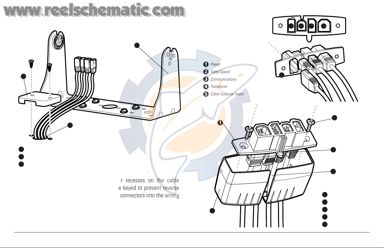
9. Insert cable connectors into the proper recesses on the cable
collector insert. The cable connectors are keyed to prevent reverse
installation, so be careful not to force the connectors into the wrong
slots. If you don’t have a cable for every hole in the insert, install the
blank plugs to protect the control head from the weather.
Cable Collector Insert
1
Screws
2
Cable Collector Cover
3
Tab on Insert
4
Slot on Cover
5
1
2
3
4
5
Power
1
Temp/Speed
2
Communications
3
Transducer
4
Cable Collector Insert
5
1 2
3 4
5
1
2
Cables Routed Behind Mounting Bracket
3
Gimbal Bracket
1
Grommet
2
Hole Cover
3
10
www.reelschematic.com
www.reelschematic.com
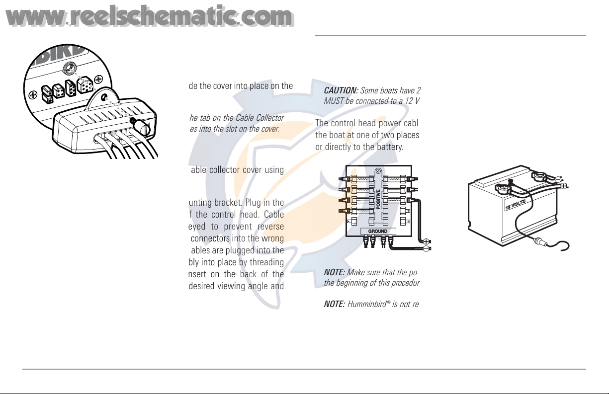
10. While holding cables in place in
the cable collector insert, thread the
cables through the slot in the bottom
of the cable collector cover, line up
the cable collector insert and cover,
then slide the cover into place on the
insert.
NOTE: The tab on the Cable Collector
insert goes into the slot on the cover.
11. Attach the cable collector insert to the cable collector cover using
the 2 Phillips screws provided.
12. Place the control head back onto the mounting bracket. Plug in the
cable collector assembly to the back of the control head. Cable
connectors and cable sockets are keyed to prevent reverse
installation, so be careful not to force the connectors into the wrong
sockets. Once the cable collector and all cables are plugged into the
back of the control head, lock the assembly into place by threading
the knurled screw into the threaded insert on the back of the
housing. Adjust the control head to the desired viewing angle and
secure by tightening the gimbal knobs.
NOTE: You may wish to dress the cabling with nylon wire ties in order to hold the
cables together and create a cleaner assembly.
The Humminbird® 900 Series™ control head is now ready for operation.
Connecting the Control Head Power Cable to the Boat
A 6' (2 m) long power cable is included to supply power to the control head.
You may shorten or lengthen the cable using 18 gauge multi-stranded
copper wire.
CAUTION: Some boats have 24 or 36 Volt electric systems, but the control head
MUST be connected to a 12 VDC power supply.
The control head power cable can be connected to the electrical system of
the boat at one of two places: a fuse panel usually located near the console,
or directly to the battery.
NOTE: Make sure that the power cable is disconnected from the control head at
the beginning of this procedure.
NOTE: Humminbird® is not responsible for over-voltage or over-current failures.
The control head must have adequate protection through the proper selection
and installation of a 3 amp fuse.
GROUND
GROUND
POSITIVE
POSITIVE
Plug Cable Connector Assembly to
Back of Control Head
11
www.reelschematic.com
www.reelschematic.com
NOTE: In order to minimize the potential for interference with other marine
electronics, a separate power source (such as a second battery) may be
necessary.
You are now ready to install the transducer. Find the section that refers to
your specific transducer installation method.
Transducer Installation
There are three different installation methods for your transducer:
• Transom Transducer
• Inside the Hull Transducer
• Trolling Motor Transducer.
Your 900 Series™ uses a Two Piece Kick-up transducer mounting bracket.
Find the section that describes the method of installation you will be using.
NOTE: If the included transducer will not work for your application, you may
exchange it, NEW and UNASSEMBLED, with mounting hardware included, for a
transducer appropriate for your application - often at very little or no charge
depending on the transducer. Call the Humminbird® Customer Resource Center
at 1-800-633-1468 for details and pricing, or visit www.humminbird.com.
NOTE: Due to the wide variety of hulls, only general instructions are presented
in this installation guide. Each boat hull represents a unique set of requirements
that should be evaluated prior to installation. In addition to the hardware
supplied with your transducer, you will need a powered hand drill and various
drill bits, various hand tools, including a ruler or straightedge, a level, a 12" plumb
line (weighted string or monofilament line), marker or pencil, safety glasses and
dust mask, and marine-grade silicone sealant.
NOTE: Please read all instructions carefully and completely before beginning the
installation process.
NOTE: When drilling holes in fiberglass hulls, it is best to start with a smaller bit
and use progressively larger drill bits to reduce the chance of chipping or flaking
the outer coating.
NOTE: Your transducer may not look exactly like the transducer shown in the
illustrations, but it will mount in exactly the same way.
1a. If a fuse terminal is available, use crimp-on type electrical
connectors (not included) that match the terminal on the fuse
panel. Attach the black wire to ground (-), and the red wire to
positive (+) 12 VDC power. Install a 3 amp fuse (not included) for
protection of the unit. Humminbird® is not responsible for over-
voltage of over-current failures.
or...
1b. If you need to wire the control head directly to a battery, obtain
and install an inline fuse holder and a 3 amp fuse (not included)
for the protection of the unit. Humminbird® is not responsible for
overvoltage or over-current failures.
12
www.reelschematic.com
www.reelschematic.com
Transom Transducer Installation
If you will be installing a transom mounted transducer, use the procedures
in this section. There are several procedures you will have to perform in order
to install a transom-mounted transducer. They are:
• Locate transducer mounting location
• Prepare the mounting location
• Assemble the transducer and perform initial mounting
• Route the transducer cable
• Connect the transducer cable
• Perform a final test of the transom transducer installation.
1. Locating the transducer mounting location
NOTE: If transom mounting is not possible because of a stepped hull or
cavitation noise, and you have a single layer fiberglass hull, In-hull installation is
an option. See Inside the Hull Transducer Installation for more information.
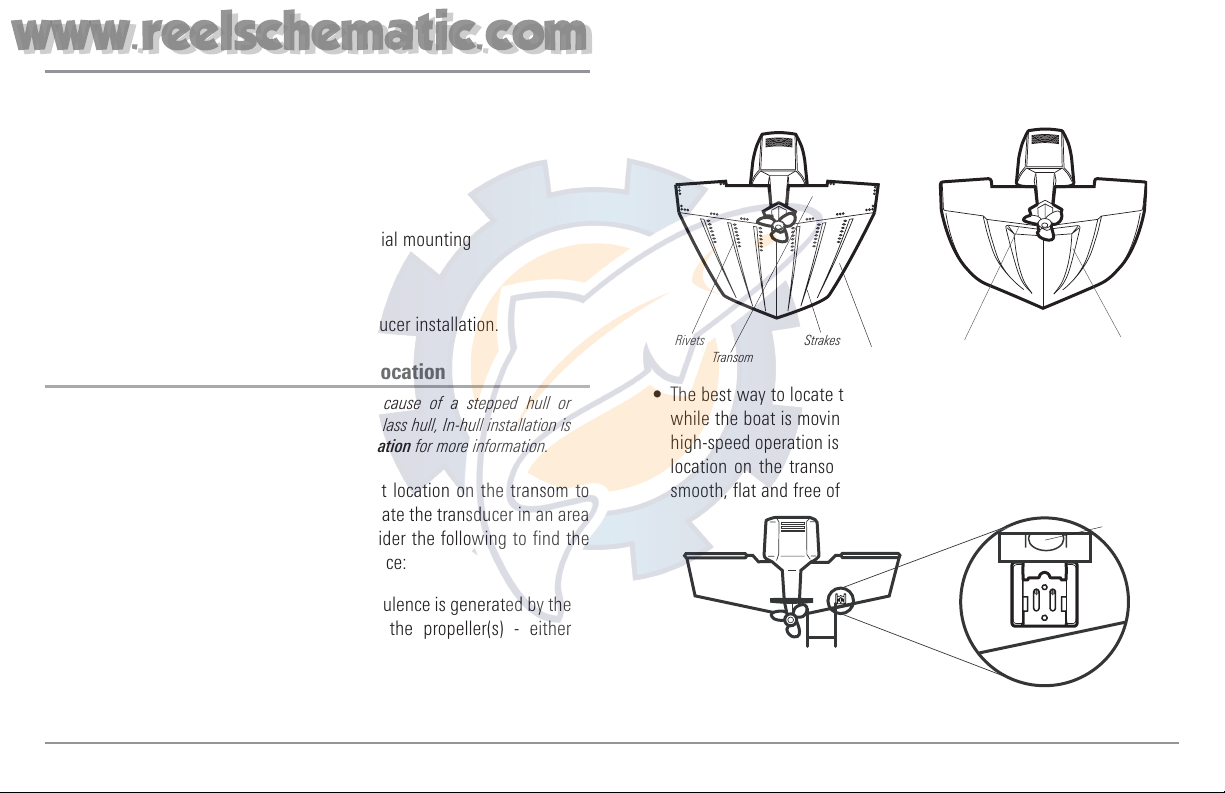
Turbulence: You must first determine the best location on the transom to
install the transducer. It is very important to locate the transducer in an area
that is relatively free of turbulent water. Consider the following to find the
best location with the least amount of turbulence:
• As the boat moves through the water, turbulence is generated by the
weight of the boat and the thrust of the propeller(s) - either
clockwise or counter-clockwise. This turbulent water is normally
confined to areas immediately aft of ribs, strakes or rows of rivets on
the bottom of the boat, and in the immediate area of the propeller(s).
Clockwise propellers create more turbulence on the port side.
On outboard or inboard/outboard boats, it is best to locate the
transducer at least 15" to the side of the propeller(s).
• The best way to locate turbulence-free water is to view the transom
while the boat is moving. This method is recommended if maximum
high-speed operation is a high priority. If this is not possible, select a
location on the transom where the hull forward of this location is
smooth, flat and free of protrusions or ribs.
15”
Find a turbulence-free location at least 15" from the propeller(s)
and not in line with trailer bunks or rollers.
Level
Areas of Possible Turbulence
Rivets Strakes
Transom Hull
Stepped Hull
Step Rib
13
www.reelschematic.com
www.reelschematic.com
• On boats with stepped hulls, it may be
possible to mount the transducer on the
step. Do not mount the transducer on
the transom behind a step to avoid
popping the transducer out of the water
at higher speeds; the transducer must
remain in the water for the control head
to maintain the sonar signal.
• If the transom is behind the propeller(s), it may be impossible to find
an area clear from turbulence, and a different mounting technique or
transducer type should be considered, such as an Inside the Hull
Transducer (see Inside the Hull Transducer Installation).
• If you plan to trailer your boat, do not mount the transducer too close
to trailer bunks or rollers to avoid moving or damaging the transducer
during loading and unloading of the boat.
• If high speed operation is critical, you may want to consider using an
In-Hull transducer instead of this Transom Mount transducer.
NOTE: The hydrodynamic shape of your transducer allows it to point straight
down without deadrise adjustment.
NOTE: If you cannot find a transom mount location that will work for your high-
speed application, find an In-Hull Transducer by contacting our Customer
Resource Center at either 1-800-633-1468 or by visiting our website at
www.humminbird.com.
2. Preparing the Mounting Location
In this procedure, you will determine the mounting location and drill two
mounting holes, using the transducer mounting bracket as a guide.
1. Make sure that the boat is level on the trailer, both from port to
starboard and from bow to stern, by placing your level on the deck
of the boat, first in one direction, then in the other.
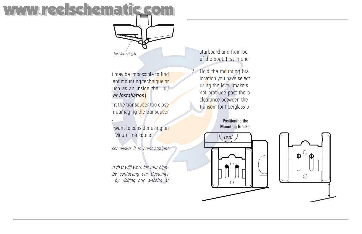
2. Hold the mounting bracket against the transom of the boat in the
location you have selected (Figure 18). Align the bracket horizontally,
using the level; make sure that the lower corner of the bracket does
not protrude past the bottom of the hull, and there is at least 1/4"
clearance between the bottom of the bracket and the bottom of the
transom for fiberglass boats, and 1/8" clearance for aluminum boats.
Positioning the
Mounting Bracket
Level
Level
Boat Hull Types Require
Different Mounting Positions
1/4” for fiberglass
1/8” for aluminum
Deadrise Angle
14
www.reelschematic.com
www.reelschematic.com
NOTE: If you have a flat-bottomed aluminum boat, some additional adjustment
may be needed to accommodate the rivets on the bottom of the boat (i.e. the gap
may need to be a little smaller than 1/8"). This will help you to avoid excessive
turbulence at high speeds.
NOTE: If your propeller moves clockwise (in forward, as you're facing the stern of
the boat from behind), mount the transducer on the starboard side, and align the
bottom right corner of the mounting bracket with the bottom of the boat. If your
propeller moves counter-clockwise (in forward, as you're facing the stern of the
boat from behind), mount the transducer on the port side, and align the bottom
left corner of the mounting bracket with the bottom of the boat.
3. Continue to hold the bracket on the transom
of the boat, and use a pencil or marker to
mark where to drill the two mounting holes.
Mark the drill holes near the top of each
slot, making sure that your mark is centered
in the slot.
NOTE: The third hole should not be drilled until the
angle and height of the transducer is finalized, which
you will not do until a later procedure.
4. Make sure that the drill bit is perpendicular
to the actual surface of the transom, NOT
parallel to the ground, before you drill.
Using a 5/32” bit, drill the two holes only to
a depth of approximately 1”.
NOTE: On fiberglass hulls, it is best to use progressively larger drill bits to reduce
the chance of chipping or flaking the outer coating.
3. Assembling the Transducer and Initial Mounting
In this procedure, you will assemble the transducer using the hardware
provided, then mount it and make adjustments to its position without locking
it in place.
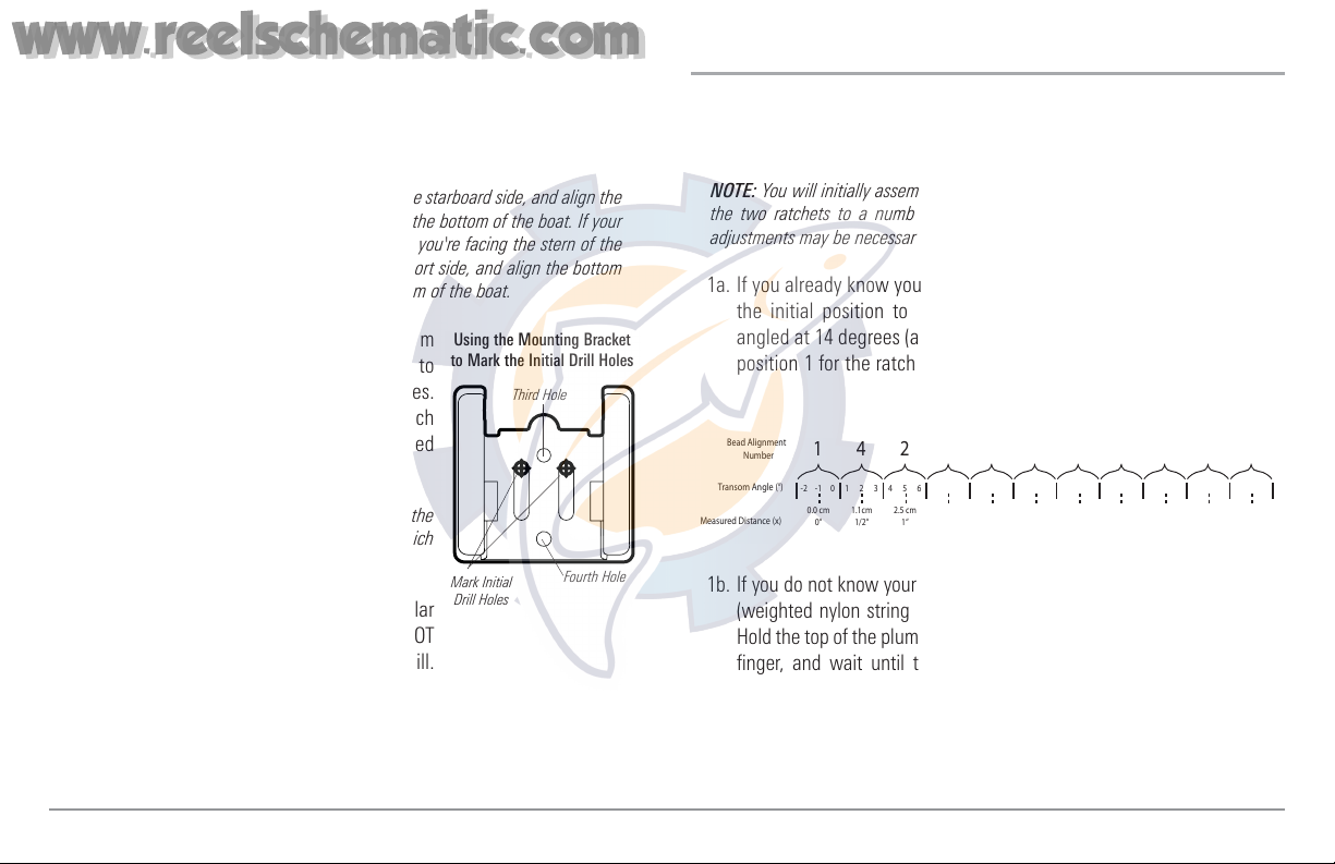
NOTE: You will initially assemble the transducer and the pivot arm by matching
the two ratchets to a numbered position on the transducer knuckle. Further
adjustments may be necessary.
1a. If you already know your transom angle, refer to the chart below for
the initial position to use to set the ratchets. If your transom is
angled at 14 degrees (a common transom angle for many boats) use
position 1 for the ratchets. In either case, go to step 2.
or...
1b. If you do not know your transom angle, measure it using a plumb line
(weighted nylon string or monofilament line) exactly 12 inches long.
Hold the top of the plumb line against the top of the transom with your
finger, and wait until the line hangs straight down. Using a ruler,
measure the distance from the bottom of the plumb line to the back of
the transom, then use the chart.
NOTE: It is important to take your measurement in the figure showing Measuring
the Transom Angle, from exactly 12 inches down from the top of the transom.
-2 -1 0 1 2 3 4 5 6 7 8 9 10 11 12 13 14 15 16 17 18 19 20 21 22 23 24
Transom Angle (°)
Bead Alignment
Number
142531425
25 26 27
3
28 29 30
1
Measured Distance (x)
1.1cm
1/2“
0.0 cm
0“
2.5 cm
1“
4.3 cm
1 5/8“
5.9 cm
2 3/8“
7.6 cm
3“
9.3cm
3 5/8“
11.1cm
4 3/8“
12.9cm
5“
14.9cm
5 7/8“
16.9cm
6 5/8“
Using the Mounting Bracket
to Mark the Initial Drill Holes
Mark Initial
Drill Holes
Third Hole
Fourth Hole
15
www.reelschematic.com
www.reelschematic.com
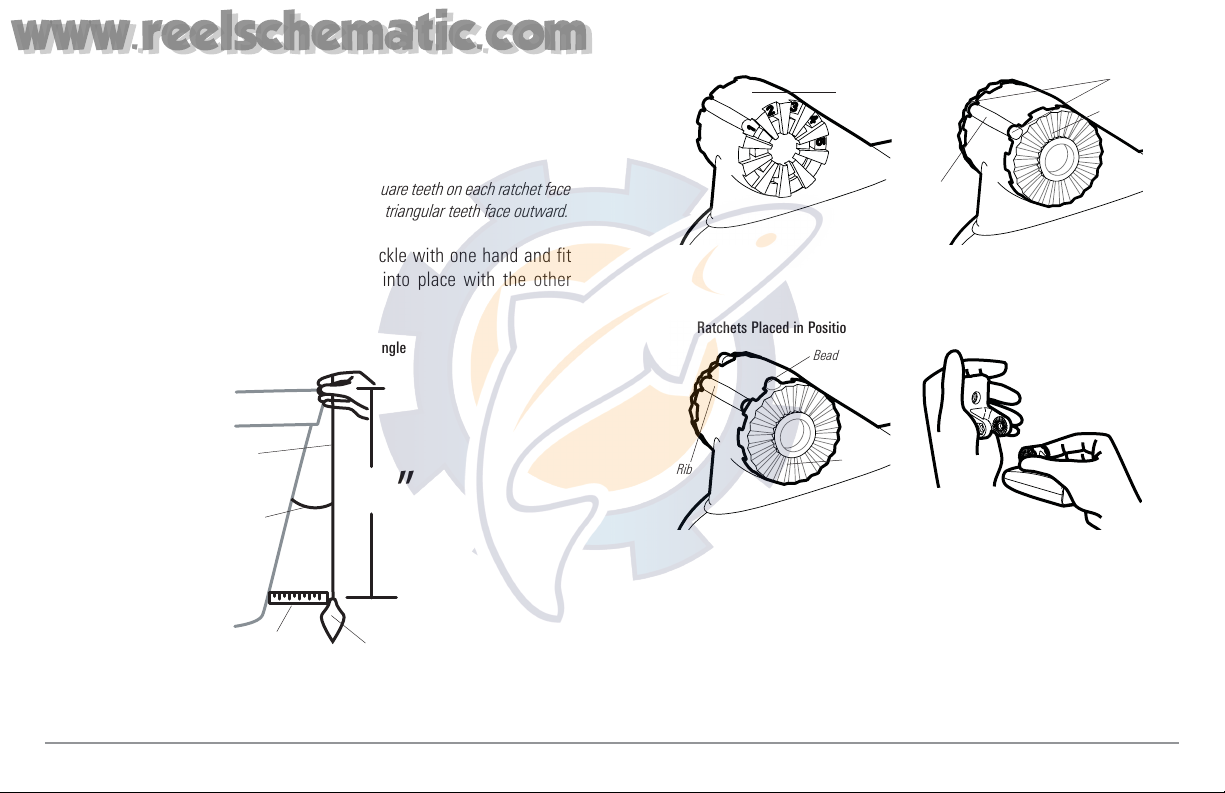
2. Place the two ratchets, one on either side of the transducer knuckle,
so that the beads on each ratchet line up with the desired position
number on the knuckle. If you are setting the ratchets at position 1,
the beads on each ratchet will line up with the rib on the transducer
knuckle to form one continuous line on the assembly.
NOTE: The ratchets are keyed; make sure that the square teeth on each ratchet face
the square teeth on the transducer knuckle, and the triangular teeth face outward.
Hold the ratchets on the transducer knuckle with one hand and fit
the pivot arm over them until it snaps into place with the other
hand. Refer to the illustration.
Transducer Knuckle Positions
Ratchets Placed in Position 1
Ratchets Placed in Position 2 Fitting the Pivot Arm Over the Ratchet
Rib at
position 1
Knuckle
Bead
Ratchet
Rib
Beads
Ratchet
12
”
Transom
Angle in
degrees
(°)
Measured
Distance (X)
Measuring the Transom Angle
Plumb
line
Weight
16
www.reelschematic.com
www.reelschematic.com
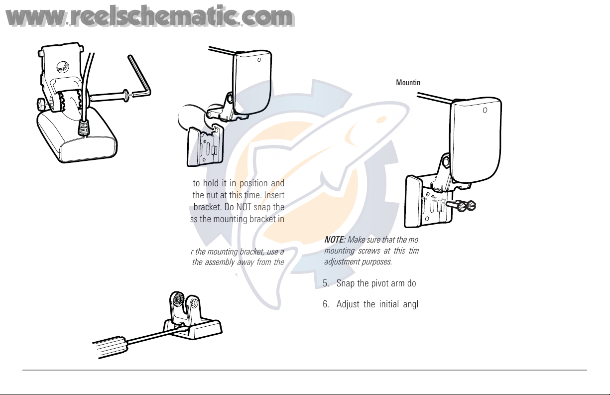
3. Put the pivot bolt through the assembly to hold it in position and
loosely install the nut, but do NOT tighten the nut at this time. Insert
the pivot arm assembly into the mounting bracket. Do NOT snap the
assembly closed, as you will need to access the mounting bracket in
the next step.
NOTE: If the pivot assembly is snapped closed over the mounting bracket, use a
flat head screwdriver or similar tool to gently pry the assembly away from the
mounting bracket).
4. Align the mounting bracket transducer assembly with the drilled
holes in the transom. With a 5/16" socket driver, mount the
assembly to the transom using the two #10 - 1" long screws
provided.
NOTE: Make sure that the mounting screws are snug, but do not fully tighten the
mounting screws at this time to allow the transducer assembly to slide for
adjustment purposes.
5. Snap the pivot arm down into place.
6. Adjust the initial angle of the transducer from back to front by
rotating the transducer until the side seam on the transducer is
almost parallel with the bottom of the boat, one click at a time in
either direction.
Mounting the Assembly to the Transom
Inserting the Pivot Bolt
Inserting the Pivot Arm Assembly
Into the Mounting Bracket
17
www.reelschematic.com
www.reelschematic.com
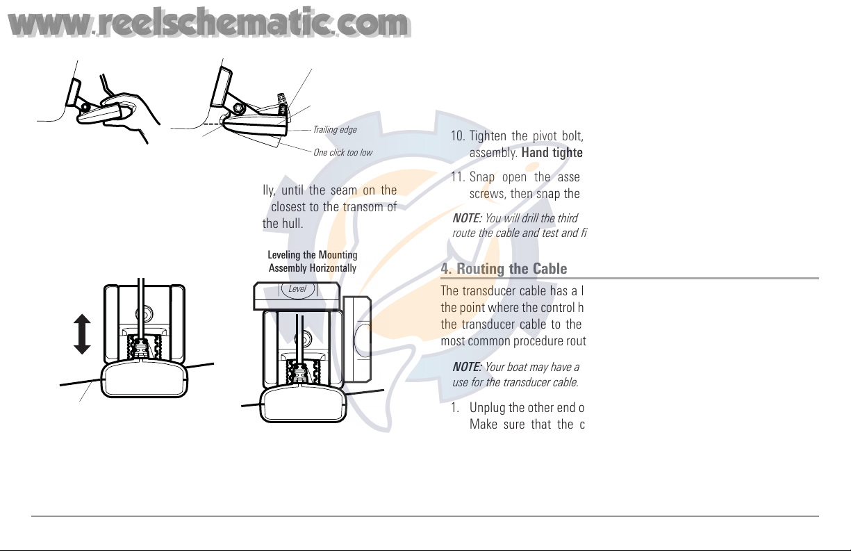
7. Adjust the transducer assembly vertically, until the seam on the
leading edge of the transducer (the edge closest to the transom of
the boat) is level and just slightly below the hull.
NOTE: The transducer has a natural downward slant of 4-5 degrees from leading
edge (closest to the boat transom) to trailing edge (farthest away from the boat).
Looking at the back of the transducer, the seam should be slightly below the
bottom of the hull.
8. Continue to adjust until the bracket is also level from port to
starboard (horizontally level as you look at the transducer from
behind the boat.
9. Mark the correct position on the transom by tracing the silhouette
of the transducer mounting bracket with a pencil or marker.
10. Tighten the pivot bolt, using the pivot screw and nut to lock the
assembly. Hand tighten only!
11. Snap open the assembly and hand-tighten the two mounting
screws, then snap the assembly closed.
NOTE: You will drill the third mounting hole and finalize the installation after you
route the cable and test and finish the installation in the following procedures.
4. Routing the Cable
The transducer cable has a low profile connector, which must be routed to
the point where the control head is mounted. There are several ways to route
the transducer cable to the area where the control head is installed. The
most common procedure routes the cable through the transom into the boat.
NOTE: Your boat may have a pre-existing wiring channel or conduit that you can
use for the transducer cable.
1. Unplug the other end of the transducer cable from the control head.
Make sure that the cable is long enough to accommodate the
planned route by running the cable over the transom.
CAUTION! Do not cut or shorten the transducer cable, and try not to damage the
cable insulation. Route the cable as far as possible from any VHF radio antenna
cables or tachometer cables to reduce the possibility of interference. If the cable
Adjusting the Transducer
Mounting Position
Seam aligned with boat hull
Leveling the Mounting
Assembly Horizontally
Level
Adjusting the Initial Transducer Angle
Leading edge
One click too low
Trailing edge
Correctly aligned
(transducer side seam
aligned with boat bottom)
One click too high
18
www.reelschematic.com
www.reelschematic.com
is too short, extension cables are available to extend the transducer cable up
to a total of 50'. For assistance, contact the Customer Resource Center at
www.humminbird.com or call 1-800-633-1468 for more information.
NOTE: The transducer can pivot up to 90 degrees in the bracket. Allow enough
slack in the cable for this movement. It is best to route the cable to the side of
the transducer so the transducer will not damage the cable during movement.
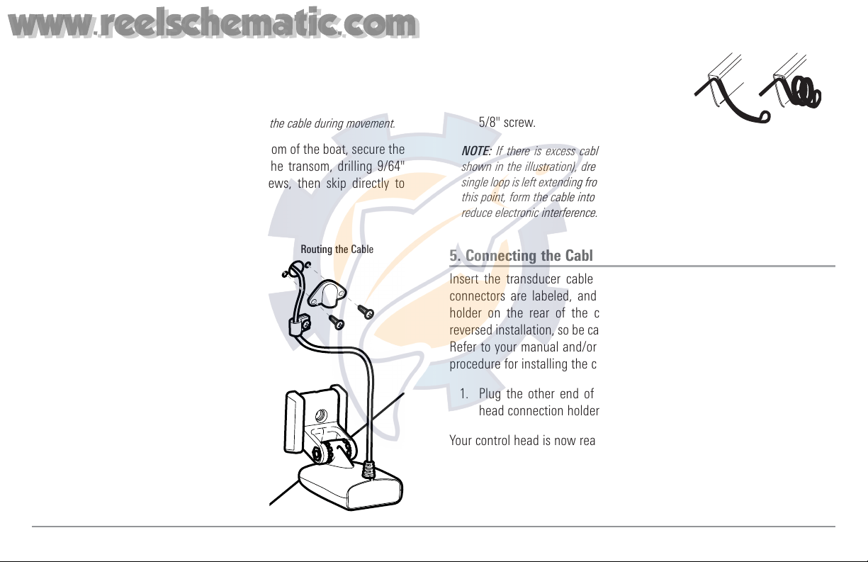
2a. If you are routing the cable over the transom of the boat, secure the
cable by attaching the cable clamp to the transom, drilling 9/64"
diameter holes for #8 x 5/8" wood screws, then skip directly to
procedure 5, Connecting the Cable.
or...
2b. If you will be routing the cable through a
hole in the transom, drill a 5/8"
diameter hole above the waterline.
Route the cable through this hole, then
fill the hole with marine-grade silicone
sealant and proceed to the next step
immediately.
3. Place the escutcheon plate over the
cable hole and use it as a guide to mark
the two escutcheon plate mounting
holes. Remove the plate, drill two 9/64"
diameter x 5/8" deep holes, and then fill
both holes with marine-grade silicone
sealant. Place the escutcheon plate over
the cable hole and attach with two
#8 x 5/8" wood screws.
4. Route and secure the cable by attaching
the cable clamp to the transom; drill one
9/64" diameter x 5/8" deep hole, then fill
hole with marine-grade silicone sealant,
then attach the cable clamp using a #8 x
5/8" screw.
NOTE: If there is excess cable that needs to be gathered at one location (as
shown in the illustration), dress the cable routed from both directions so that a
single loop is left extending from the storage location. Doubling the cable up from
this point, form the cable into a coil. Storing excess cable using this method can
reduce electronic interference.
5. Connecting the Cable
Insert the transducer cable into the appropriate terminal slot. The cable
connectors are labeled, and there are corresponding labels on the cable
holder on the rear of the control head. The slots are keyed to prevent
reversed installation, so be careful not to force the connector into the holder.
Refer to your manual and/or control head installation guide for the correct
procedure for installing the cable connectors to the control head.
1. Plug the other end of the transducer cable back into the control
head connection holder.
Your control head is now ready for operation.
Storing Excess Cable
Routing the Cable
19
www.reelschematic.com
www.reelschematic.com
6. Test and Finish the Installation
Once you have installed both the control head and the transom transducer, and
have routed all the cables, you must perform a final test before locking the
transducer in place. Testing should be performed with the boat in the water,
although you can initially confirm basic operation with the boat out of the water.
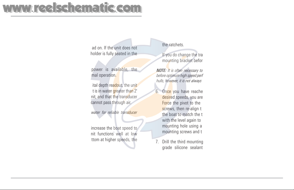
1. Press POWER once to turn the control head on. If the unit does not
power up, make sure that the connector holder is fully seated in the
receptacle and that power is available.
2. If all connections are correct and power is available, the
Humminbird® control head will enter Normal operation.
3. If the bottom is visible on-screen with a digital depth readout, the unit
is working properly. Make sure that the boat is in water greater than 2'
but less than the depth capability of the unit, and that the transducer
is fully submerged, since the sonar signal cannot pass through air.
NOTE: The transducer must be submerged in water for reliable transducer
detection.
4. If the unit is working properly, gradually increase the boat speed to
test high-speed performance. If the unit functions well at low
speeds, but begins to skip or miss the bottom at higher speeds, the
transducer requires adjustment.
5. If you have the correct angle set on the transducer, yet lose a bottom
reading at high speed, adjust the height and the running angle in
small increments to give you the ideal transducer position for your
boat. First, adjust the height in small increment.
NOTE: The deeper the transducer is in the water, the more likely that a rooster
tail of spray will be generated at high speeds, so make sure that the transducer
is as high as it can be and still be submerged in the water.
If you are still not getting good high speed readings, you may need
to disassemble the transducer mounting assembly and re-position
the ratchets.
If you do change the transducer position, re-trace the position of the
mounting bracket before proceeding.
NOTE: It is often necessary to make several incremental transducer adjustments
before optimum high speed performance is achieved. Due to the wide variety of boat
hulls, however, it is not always possible to obtain high speed depth readings.
6. Once you have reached a consistently good sonar signal at the
desired speeds, you are ready to lock down the transducer settings.
Force the pivot to the Up position to gain access to the mounting
screws, then re-align the mounting bracket against the transom of
the boat to match the traced silhouette. Check the bracket position
with the level again to make sure it is still level, then mark the third
mounting hole using a pencil or marker. Unscrew and remove the
mounting screws and the transducer assembly and set aside.
7. Drill the third mounting hole, using a 5/32” drill bit. Use a marine-
grade silicone sealant to fill all three drilled mounting holes,
especially if the holes penetrated the transom wall.
NOTE: On fiberglass hulls, it is best to use progressively larger drill bits to reduce
the chance of chipping or flaking the outer coating.
20
www.reelschematic.com
www.reelschematic.com
8. Re-position the transducer assembly against
the transom of the boat, then hand-install
all three screws. Make sure that the
transducer location and the pivot angle
have not changed, then fully tighten all
three mounting screws. Snap the pivot
back down. If you have performed the
preceding procedures correctly, the
transducer should be level and at the
right height for optimal operation.
Inside the Hull Transducer Installation
If you choose to mount your transducer inside the hull of your boat, perform the
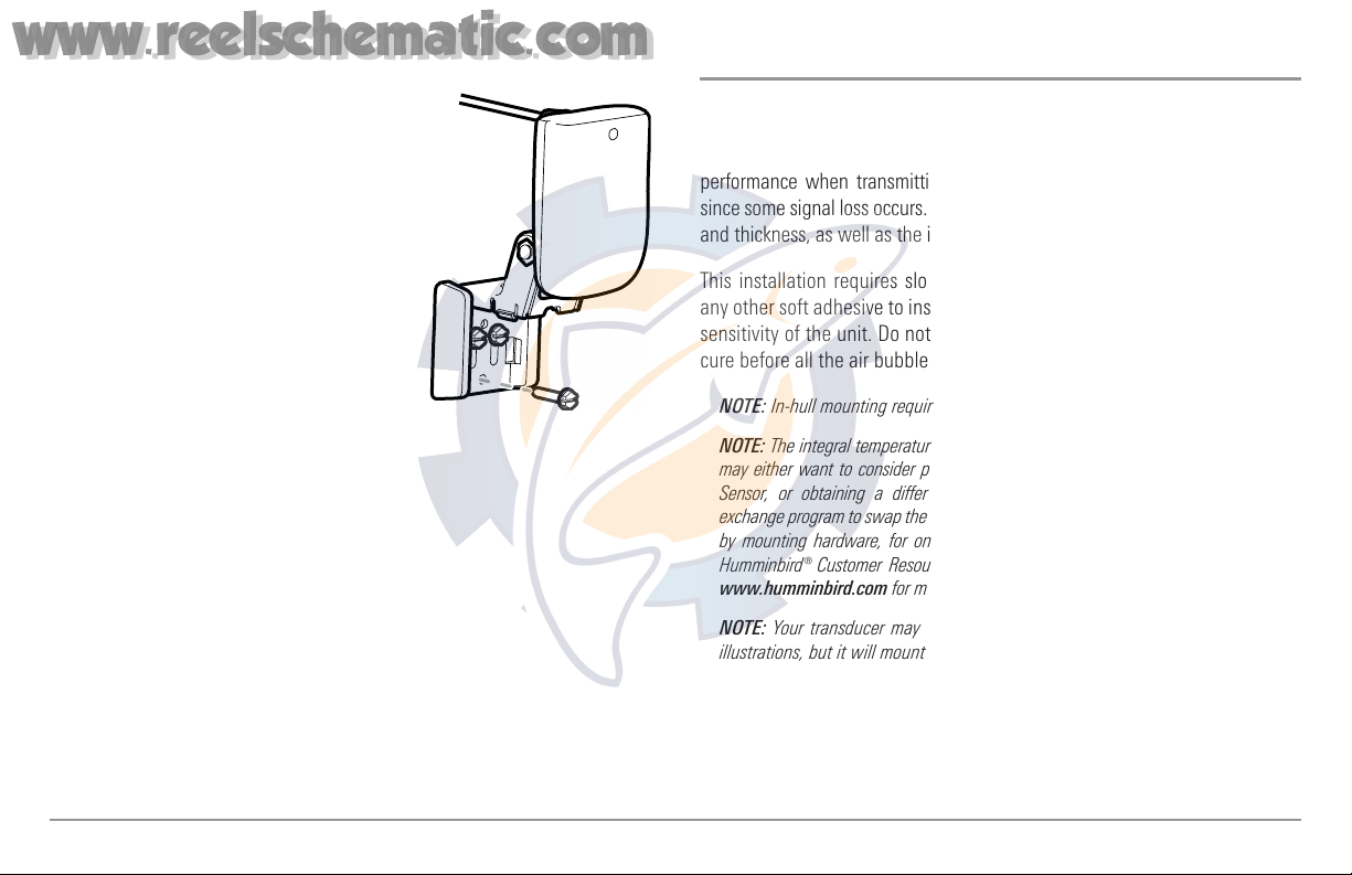
procedures in this section. In-hull mounting generally produces good results in
single thickness fiberglass-hulled boats. Humminbird® cannot guarantee depth
performance when transmitting and receiving through the hull of the boat,
since some signal loss occurs. The amount of loss depends on hull construction
and thickness, as well as the installation position and process.
This installation requires slow-cure two-part epoxy. Do not use silicone or
any other soft adhesive to install the transducer, as this material reduces the
sensitivity of the unit. Do not use five-minute epoxy, as it has a tendency to
cure before all the air bubbles can be purged, thus reducing signal strength.
NOTE: In-hull mounting requires an installed and operational control head.
NOTE: The integral temperature probe will not work with in-hull mounting, so you
may either want to consider purchasing a Temperature/Speed accessory, a Temp
Sensor, or obtaining a different transducer. Humminbird® offers a transducer
exchange program to swap the NEW and UNASSEMBLED transducer, accompanied
by mounting hardware, for one without an integral temperature probe. Call the
Humminbird® Customer Resource Center at 1-800-633-1468 for details, or visit
www.humminbird.com for more information.
NOTE: Your transducer may not look exactly like the transducer shown in the
illustrations, but it will mount in exactly the same way.
• Locate transducer mounting location
• Perform a trial installation
• Route the transducer cable
• Permanently mount the transducer.
Fully Tighten All Three
Mounting Screws
21
www.reelschematic.com
www.reelschematic.com
1. Determine the transducer mounting location
Decide where to install the transducer on the inside of the hull. Consider the
following to find the best location:
• Observe the outside of the boat hull to find the areas that are mostly
free from turbulent water. Avoid ribs, strakes and other protrusions,
as these create turbulence.
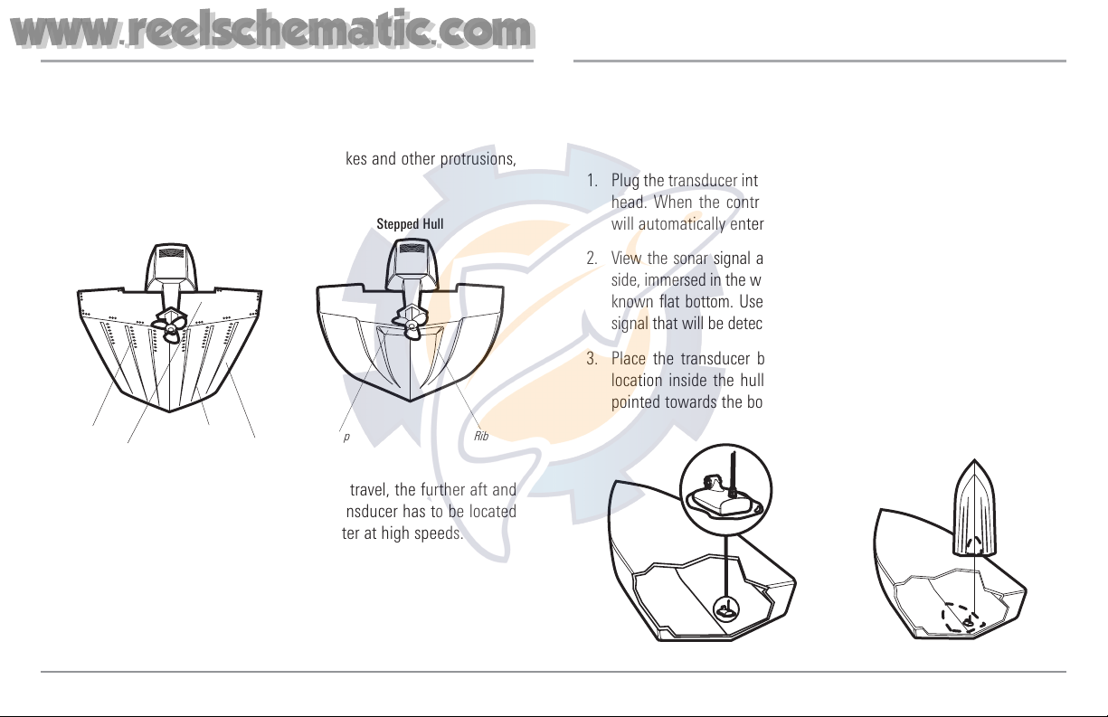
• As a general rule, the faster the boat can travel, the further aft and
closer to the centerline of the hull the transducer has to be located
in order to remain in contact with the water at high speeds.
2. Trial installation
You will not be able to adjust the mounting after an inside the hull
transducer is installed. It is best, therefore, to perform a trial installation first
that includes running the boat at various speeds, in order to determine the
best mounting area before permanently mounting the transducer.
1. Plug the transducer into the control head, then power up the control
head. When the control head detects a functioning transducer, it
will automatically enter Normal operating mode.
2. View the sonar signal at its best by holding the transducer over the
side, immersed in the water, so that it is pointing straight down over a
known flat bottom. Use the display to benchmark against the sonar
signal that will be detected once the transducer is placed in the hull.
3. Place the transducer body face down at the identified mounting
location inside the hull, with the end that has the mounting ears
pointed towards the bow of the boat.
Preferred Mounting Area
Areas of Possible Turbulence
Rivets Strakes
Transom Hull
Stepped Hull
Step Rib
22
www.reelschematic.com
www.reelschematic.com
 Loading...