


 Loading...
service |
|
|
hp LaserJet 2400 series |
||

HP LaserJet 2400 Series printer
Service Manual

Copyright information
© 2005 Copyright Hewlett-Packard
Development Company, L.P.
Reproduction, adaptation, or translation without prior written permission is prohibited, except as allowed under the copyright laws.
The information contained herein is subject to change without notice.
The only warranties for HP products and services are set forth in the express warranty statements accompanying such products and services. Nothing herein should be construed as constituting an additional warranty. HP shall not be liable for technical or editorial errors or omissions contained herein.
Part number Q5956-90940
Edition 2, 8/2005
Safety information
WARNING!
Potential Shock Hazard
Always follow basic safety precautions when using this product to reduce risk of injury from fire or electric shock.
Read and understand all instructions in the user guide.
Observe all warnings and instructions marked on the product.
Use only a grounded electrical outlet when connecting the printer to a power source. If you do not know whether the outlet is grounded, check with a qualified electrician.
Do not touch the contacts on the end of any of the sockets on the printer. Replace damaged cords immediately.
Unplug this product from wall outlets before cleaning.
Do not install or use this product near water or when you are wet.
Install the product securely on a stable surface.
Install the product in a protected location where no one can step on or trip over the power cord and where the power cord will not be damaged.
If the product does not operate normally, see the online user guide.
Refer all servicing questions to qualified personnel.
Information regarding FCC Class B, Parts 15 and 68 requirements can be found in the user guide.
Trademark credits
Adobe®, Acrobat®, PostScript®, and the Acrobat Logo® are trademarks of Adobe Systems Incorporated.
Java™ is a U.S. trademark of Sun Microsystems, Inc.
Microsoft®, Windows®, and Windows NT® are U.S. registered trademarks of Microsoft Corporation.
UNIX® is a registered trademark of The Open Group.
ENERGY STAR® and the ENERGY STAR logo® are U.S. registered marks of the United States Environmental Protection Agency.
Table of contents
1 Product Information |
|
Chapter contents..................................................................................................................................... |
1 |
Printer configurations............................................................................................................................... |
2 |
HP LaserJet 2400 Series printer base models....................................................................... |
2 |
Features................................................................................................................................................... |
4 |
Specifications........................................................................................................................................... |
7 |
Physical specifications............................................................................................................ |
7 |
Electrical specifications........................................................................................................... |
7 |
Acoustic emissions................................................................................................................. |
9 |
Operating environment........................................................................................................... |
9 |
Media specifications.............................................................................................................................. |
10 |
Supported types and sizes of print media ........................................................................... |
10 |
Paper and print media........................................................................................................... |
11 |
Printing and paper storage environment.............................................................................. |
12 |
Envelopes............................................................................................................................. |
12 |
Envelopes with double side seams...................................................................................... |
13 |
Envelopes with adhesive strips or flaps................................................................................ |
14 |
Envelope margins................................................................................................................. |
14 |
Envelope storage.................................................................................................................. |
14 |
Labels.................................................................................................................................... |
14 |
Transparencies..................................................................................................................... |
14 |
Print Cartridge Limited Warranty Statement......................................................................................... |
15 |
HP LaserJet printing supplies................................................................................................................ |
16 |
Declaration of conformity....................................................................................................................... |
17 |
Country-/region-specific safety statements........................................................................................... |
18 |
Laser safety statement......................................................................................................... |
18 |
Canadian DOC statement..................................................................................................... |
18 |
Japanese VCCI statement.................................................................................................... |
18 |
Korean EMI statement.......................................................................................................... |
18 |
Finnish laser statement......................................................................................................... |
19 |
2 Installation |
|
Chapter contents................................................................................................................................... |
21 |
Operating environment ......................................................................................................................... |
22 |
Interface ports ....................................................................................................................................... |
23 |
Software................................................................................................................................................. |
24 |
Operating systems and printer components......................................................................... |
24 |
Printer drivers........................................................................................................................ |
25 |
Software for Macintosh computers....................................................................................... |
26 |
ENWW |
iii |
PPDs.................................................................................................................... |
26 |
HP LaserJet Utility................................................................................................ |
26 |
3 Operation |
|
Chapter contents................................................................................................................................... |
27 |
Control panel......................................................................................................................................... |
28 |
Control-panel layout.............................................................................................................. |
28 |
Control-panel buttons............................................................................................................ |
29 |
Control-panel lights............................................................................................................... |
29 |
Control-panel language........................................................................................................ |
30 |
Printing control-panel menus................................................................................................ |
30 |
To print a control-panel menu map...................................................................... |
30 |
Selecting which tray is used for printing ............................................................................................... |
31 |
Understanding tray order...................................................................................................... |
31 |
Customizing tray 1 operation................................................................................................ |
31 |
Printing by type and size of media (locking trays)................................................................ |
32 |
Feeding media from tray 1 manually.................................................................................... |
33 |
Selecting the correct fuser mode........................................................................................................... |
34 |
Using the embedded Web server.......................................................................................................... |
35 |
Opening the embedded Web server..................................................................................... |
35 |
Information tab...................................................................................................................... |
36 |
Settings tab........................................................................................................................... |
36 |
Networking tab ..................................................................................................................... |
37 |
Other links............................................................................................................................. |
37 |
Using HP Web Jetadmin software......................................................................................................... |
38 |
Using the HP Toolbox............................................................................................................................ |
39 |
Supported operating systems............................................................................................... |
39 |
Supported browsers.............................................................................................................. |
39 |
To view the HP Toolbox........................................................................................................ |
39 |
Status tab.............................................................................................................................. |
40 |
Troubleshooting tab.............................................................................................................. |
40 |
Alerts tab............................................................................................................................... |
41 |
Set up status alerts page..................................................................................... |
41 |
Administrative settings page................................................................................ |
41 |
Documentation tab................................................................................................................ |
41 |
Device Settings window........................................................................................................ |
41 |
Toolbox links......................................................................................................................... |
42 |
Other links............................................................................................................................. |
42 |
Uninstalling the HP Toolbox.................................................................................................................. |
43 |
To uninstall the HP Toolbox by using the Windows desktop shortcut.................................. |
43 |
Checking the printer configuration......................................................................................................... |
44 |
Menu map............................................................................................................................. |
44 |
To print a menu map............................................................................................ |
44 |
Configuration page................................................................................................................ |
44 |
To print a configuration page at the control panel............................................... |
45 |
Supplies status page............................................................................................................. |
46 |
To print a supplies status page at the control panel............................................ |
46 |
PS or PCL font list................................................................................................................. |
47 |
To print a PS or PCL font list............................................................................... |
47 |
Managing the print cartridge.................................................................................................................. |
48 |
iv |
ENWW |
HP print cartridges................................................................................................................ |
48 |
Non-HP print cartridges........................................................................................................ |
48 |
Print-cartridge authentication................................................................................................ |
48 |
Print-cartridge storage.......................................................................................................... |
48 |
Print-cartridge life expectancy.............................................................................................. |
49 |
Checking the supply level..................................................................................................... |
49 |
To check the supply level by using the control panel.......................................... |
49 |
To check the supply level by using the embedded Web server.......................... |
49 |
To check the supply level by using the HP Toolbox software............................. |
49 |
To check the supply levels by using HP Web Jetadmin...................................... |
49 |
Cartridge-low and cartridge-out conditions........................................................................... |
49 |
When the cartridge is low on toner or drum life................................................... |
49 |
When the cartridge is out of toner or drum life..................................................... |
50 |
4 Maintenance |
|
Chapter contents................................................................................................................................... |
51 |
Cleaning the printer............................................................................................................................... |
52 |
Cleaning the outside............................................................................................................. |
52 |
Cleaning the paper path and print-cartridge areas .............................................................. |
52 |
To clean the inside of the printer.......................................................................... |
52 |
Cleaning the fuser................................................................................................................. |
53 |
To run the cleaning page..................................................................................... |
53 |
5 Theory of operation |
|
Chapter contents................................................................................................................................... |
55 |
Introduction............................................................................................................................................ |
56 |
Internal components.............................................................................................................................. |
57 |
Timing.................................................................................................................................................... |
59 |
Engine control system........................................................................................................................... |
61 |
Laser/scanner system........................................................................................................................... |
63 |
Pickup/feed/delivery system.................................................................................................................. |
64 |
Image-formation system........................................................................................................................ |
66 |
Step 1: Primary charging...................................................................................................... |
67 |
Step 2: Laser beam exposure............................................................................................... |
67 |
Step 3: Developing................................................................................................................ |
67 |
Step 4: Transfer.................................................................................................................... |
68 |
Step 5: Separation................................................................................................................ |
68 |
Step 6: Fusing....................................................................................................................... |
68 |
Step 7: Drum cleaning.......................................................................................................... |
69 |
Print cartridge memory system.............................................................................................................. |
70 |
6 Removal and replacement |
|
Chapter contents................................................................................................................................... |
71 |
Introduction............................................................................................................................................ |
72 |
Removal and replacement strategy ..................................................................................... |
72 |
Electrostatic discharge.......................................................................................................... |
72 |
User-replaceable parts......................................................................................................... |
72 |
Required tools....................................................................................................................... |
72 |
Before performing service..................................................................................................................... |
74 |
ENWW |
v |
Pre-service procedures......................................................................................................... |
74 |
Parts removal order.............................................................................................................. |
74 |
Covers................................................................................................................................................... |
76 |
Right-side cover.................................................................................................................... |
76 |
Back cover............................................................................................................................ |
76 |
I/O cover................................................................................................................................ |
80 |
Left-side cover...................................................................................................................... |
81 |
Top, right cover..................................................................................................................... |
83 |
Top cover.............................................................................................................................. |
83 |
Front, right cover................................................................................................................... |
85 |
Control panel......................................................................................................................................... |
87 |
Formatter............................................................................................................................................... |
89 |
Fuser...................................................................................................................................................... |
93 |
Laser/scanner........................................................................................................................................ |
98 |
Right-side handle................................................................................................................................. |
101 |
ECU..................................................................................................................................................... |
103 |
Access plate........................................................................................................................................ |
109 |
Power supply....................................................................................................................................... |
110 |
Gear assembly..................................................................................................................................... |
115 |
Tray 1 solenoid.................................................................................................................................... |
119 |
Tray 2 solenoid.................................................................................................................................... |
120 |
E-label reader (memory tag)................................................................................................................ |
121 |
Face-down-roller shaft......................................................................................................................... |
123 |
Cartridge door...................................................................................................................................... |
125 |
Transfer roller...................................................................................................................................... |
128 |
Registration assembly......................................................................................................................... |
129 |
Tray 1 pickup roller.............................................................................................................................. |
132 |
Tray 2 pickup roller.............................................................................................................................. |
133 |
Separation pad.................................................................................................................................... |
135 |
7 Troubleshooting |
|
Chapter contents................................................................................................................................. |
137 |
Troubleshooting tree............................................................................................................................ |
138 |
Troubleshooting flowchart................................................................................................................... |
139 |
1. Does the control-panel display show READY?.............................................................. |
139 |
2. Can you print a configuration page? .............................................................................. |
139 |
3. Can you print from a program? ...................................................................................... |
140 |
4. Does the job print as expected?..................................................................................... |
141 |
5. Does the printer select the correct trays?....................................................................... |
142 |
Troubleshooting tools.......................................................................................................................... |
144 |
Information pages............................................................................................................... |
144 |
Menu map.......................................................................................................... |
145 |
Configuration page............................................................................................. |
146 |
Supplies status page.......................................................................................... |
148 |
Embedded Web server ...................................................................................................... |
149 |
Gaining access to the embedded Web server................................................................... |
149 |
Information tab................................................................................................... |
149 |
Settings tab........................................................................................................ |
150 |
Networking tab .................................................................................................. |
150 |
Other links.......................................................................................................... |
150 |
vi |
ENWW |
Printer Status and Alerts software ..................................................................................... |
151 |
To select status messages................................................................................ |
152 |
To view status messages and information......................................................... |
152 |
Control-panel menus........................................................................................................................... |
153 |
Using control-panel menus................................................................................................. |
153 |
Resets submenu................................................................................................................. |
153 |
Diagnostics menu............................................................................................................... |
154 |
Service menu (service PIN codes)..................................................................................... |
155 |
Service ID........................................................................................................... |
156 |
Restoring the Service ID.................................................................................... |
156 |
Converting the Service ID to an actual date...................................................... |
156 |
Printer resets and power-on modes.................................................................................................... |
158 |
Cold reset ........................................................................................................................... |
158 |
To perform a cold reset...................................................................................... |
158 |
NVRAM initialization .......................................................................................................... |
158 |
To initialize NVRAM........................................................................................... |
158 |
Compact Flash initialization ............................................................................................... |
159 |
To initialize the Compact Flash card.................................................................. |
159 |
Perform Self test................................................................................................................. |
159 |
Save + Restore................................................................................................................... |
159 |
Proper replacement of both the Formatter and the Engine Control Unit |
|
(ECU - also known as the DC Controller).......................................................... |
160 |
Proper replacement of the Formatter only......................................................... |
161 |
Proper replacement of the Engine Control Unit (ECU) only.............................. |
161 |
Test pages .......................................................................................................................................... |
162 |
Engine-test page ................................................................................................................ |
162 |
Formatter test page............................................................................................................. |
162 |
Interface troubleshooting .................................................................................................................... |
163 |
Communications checks..................................................................................................... |
163 |
Computer direct connect (parallel) test ............................................................. |
163 |
EIO troubleshooting ........................................................................................................... |
163 |
Jetdirect page..................................................................................................... |
164 |
Solving general printing problems....................................................................................................... |
165 |
Clearing jams....................................................................................................................................... |
166 |
Avoiding jams ..................................................................................................................... |
166 |
Typical jam locations........................................................................................................... |
167 |
Clearing jams in the print-cartridge area ........................................................... |
168 |
Clearing jams in the input trays ......................................................................... |
169 |
Clearing jams in the output areas ..................................................................... |
170 |
Clearing jams in the duplexer area.................................................................... |
172 |
Media handling problems ................................................................................................................... |
174 |
Multiple pages feed ............................................................................................................ |
174 |
Pages are wrinkled or folded.............................................................................................. |
174 |
Pages are skewed ............................................................................................................. |
175 |
Understanding printer messages........................................................................................................ |
176 |
Using the printer online Help system.................................................................................. |
176 |
Resolving persistent messages.......................................................................................... |
176 |
Correcting print-quality problems ....................................................................................................... |
191 |
Print-quality checklist ......................................................................................................... |
191 |
Image-defect examples...................................................................................................... |
191 |
ENWW |
vii |
Light print (partial page) ..................................................................................................... |
193 |
Light print (entire page) ...................................................................................................... |
193 |
Specks ............................................................................................................................... |
194 |
Dropouts ............................................................................................................................ |
194 |
Lines ................................................................................................................................... |
195 |
Gray background ............................................................................................................... |
195 |
Toner smear ....................................................................................................................... |
196 |
Loose toner ........................................................................................................................ |
196 |
Repeating defects .............................................................................................................. |
197 |
Repeating image ................................................................................................................ |
197 |
Misformed characters ........................................................................................................ |
198 |
Page skew.......................................................................................................................... |
198 |
Curl or wave ....................................................................................................................... |
199 |
Wrinkles or creases ........................................................................................................... |
199 |
Vertical white lines ............................................................................................................. |
200 |
Tire tracks .......................................................................................................................... |
200 |
White spots on black .......................................................................................................... |
201 |
Scattered lines ................................................................................................................... |
201 |
Blurred print ....................................................................................................................... |
202 |
Random image repetition ................................................................................................... |
202 |
Troubleshooting common Windows problems ................................................................................... |
203 |
Troubleshooting common Macintosh problems.................................................................................. |
204 |
Troubleshooting common PostScript problems ................................................................................. |
205 |
General problems............................................................................................................... |
205 |
Specific errors..................................................................................................................... |
205 |
Printer component locations................................................................................................................ |
206 |
Main assemblies................................................................................................................. |
206 |
Main parts........................................................................................................................... |
207 |
Sensors and switches......................................................................................................... |
208 |
Motors, fans, and solenoids................................................................................................ |
209 |
PCAs................................................................................................................................... |
210 |
500-Sheet paper feeder...................................................................................................... |
211 |
Wiring diagrams................................................................................................................................... |
212 |
General timing diagrams..................................................................................................................... |
215 |
8 Parts and diagrams |
|
Chapter contents................................................................................................................................. |
217 |
Ordering parts and supplies................................................................................................................ |
218 |
Parts.................................................................................................................................... |
218 |
Related documentation and software................................................................................. |
218 |
Supplies.............................................................................................................................. |
218 |
Accessories......................................................................................................................................... |
219 |
Accessories and supplies................................................................................................... |
219 |
Covers................................................................................................................................................. |
222 |
Internal components............................................................................................................................ |
224 |
Tray 2 pickup assembly....................................................................................................................... |
236 |
Alphabetical parts list........................................................................................................................... |
238 |
Numerical parts list.............................................................................................................................. |
246 |
Index.................................................................................................................................................................... |
255 |
viii |
ENWW |
List of tables
Table 1-1 |
Feature designations for HP LaserJet 2400 Series printers............................................................ |
2 |
Table 1-2 |
Speed............................................................................................................................................... |
4 |
Table 1-3 |
Resolution......................................................................................................................................... |
4 |
Table 1-4 |
Paper handling................................................................................................................................. |
4 |
Table 1-5 |
Memory and processor..................................................................................................................... |
4 |
Table 1-6 |
Interface connections and networking.............................................................................................. |
5 |
Table 1-7 |
Language and fonts.......................................................................................................................... |
5 |
Table 1-8 |
Print cartridge................................................................................................................................... |
5 |
Table 1-9 |
Energy savings................................................................................................................................. |
6 |
Table 1-10 |
Economical printing.......................................................................................................................... |
6 |
Table 1-11 |
Accessibility...................................................................................................................................... |
6 |
Table 1-12 |
Product dimensions.......................................................................................................................... |
7 |
Table 1-13 |
Product dimensions, with all doors and trays fully opened.............................................................. |
7 |
Table 1-14 |
Power requirements......................................................................................................................... |
7 |
Table 1-15 |
Power consumption (average, in watts)........................................................................................... |
7 |
Table 1-16 |
Sound power and pressure level (HP LaserJet 2400 series).......................................................... |
9 |
Table 5-1 |
Operation sequences..................................................................................................................... |
59 |
Table 5-2 |
Power-on sequence....................................................................................................................... |
59 |
Table 7-1 |
Resets submenu.......................................................................................................................... |
153 |
Table 7-2 |
Diagnostics menu......................................................................................................................... |
154 |
Table 7-3 |
Common causes of jams.............................................................................................................. |
166 |
Table 7-4 |
Causes for multiple pages feeding............................................................................................... |
174 |
Table 7-5 |
Causes for wrinkled or folded paper at the paper-path entrance................................................ |
174 |
Table 7-6 |
Causes for wrinkled or folded paper at the paper-path exit......................................................... |
174 |
Table 7-7 |
Causes for skewed pages............................................................................................................ |
175 |
Table 7-8 |
Interpreting control-panel messages............................................................................................ |
176 |
Table 7-9 |
Problems with Mac OS 9.x........................................................................................................... |
204 |
Table 7-10 |
Problems with Mac OS X............................................................................................................. |
204 |
Table 8-1 |
Technical support Web sites........................................................................................................ |
218 |
Table 8-2 |
Covers.......................................................................................................................................... |
223 |
Table 8-3 |
Internal components (1 of 4)........................................................................................................ |
225 |
Table 8-4 |
Internal components (2 of 4)........................................................................................................ |
229 |
Table 8-5 |
Internal components (3 of 4)........................................................................................................ |
233 |
Table 8-6 |
Internal components (4 of 4)........................................................................................................ |
235 |
Table 8-7 |
Tray 2 pickup assembly................................................................................................................ |
237 |
Table 8-8 |
Alphabetical parts list................................................................................................................... |
238 |
Table 8-9 |
Numerical parts list....................................................................................................................... |
246 |
ENWW |
ix |
x |
ENWW |
List of figures
Figure 1-1 |
HP LaserJet 2400 Series printer base model, front/right-side view................................................. |
2 |
Figure 1-2 |
HP LaserJet 2400 Series printer base model, right-side/rear view................................................. |
3 |
Figure 3-1 |
Location of the control panel.......................................................................................................... |
28 |
Figure 3-2 |
Control-panel layout....................................................................................................................... |
28 |
Figure 5-1 |
Block diagram................................................................................................................................. |
56 |
Figure 5-2 |
Cross-section of printer.................................................................................................................. |
57 |
Figure 5-3 |
Engine control system.................................................................................................................... |
61 |
Figure 5-4 |
Engine control system circuit diagram........................................................................................... |
62 |
Figure 5-5 |
Laser/scanner system.................................................................................................................... |
63 |
Figure 5-6 |
Pickup/feed/delivery system........................................................................................................... |
65 |
Figure 5-7 |
Print cartridge diagram................................................................................................................... |
66 |
Figure 5-8 |
Image-formation system................................................................................................................. |
66 |
Figure 5-9 |
Primary charging............................................................................................................................ |
67 |
Figure 5-10 |
Developing...................................................................................................................................... |
67 |
Figure 5-11 |
Transfer.......................................................................................................................................... |
68 |
Figure 5-12 |
Separation...................................................................................................................................... |
68 |
Figure 5-13 |
Fusing............................................................................................................................................. |
69 |
Figure 5-14 |
Drum cleaning................................................................................................................................ |
69 |
Figure 5-15 |
Print cartridge memory tag ............................................................................................................ |
70 |
Figure 6-1 |
Parts removal diagram................................................................................................................... |
75 |
Figure 6-2 |
Removing the right-side cover....................................................................................................... |
76 |
Figure 6-3 |
Removing the back cover (1 of 3).................................................................................................. |
77 |
Figure 6-4 |
Removing the back cover (2 of 3).................................................................................................. |
78 |
Figure 6-5 |
Removing the back cover (3 of 3).................................................................................................. |
79 |
Figure 6-6 |
Removing the I/O cover.................................................................................................................. |
80 |
Figure 6-7 |
Removing the left-side cover (1 of 2)............................................................................................. |
81 |
Figure 6-8 |
Removing the left-side cover (2 of 2)............................................................................................. |
82 |
Figure 6-9 |
Removing the top, right cover........................................................................................................ |
83 |
Figure 6-10 |
Removing the top cover................................................................................................................. |
84 |
Figure 6-11 Removing the front, right cover (1 of 2)......................................................................................... |
85 |
|
Figure 6-12 Removing the front, right cover (2 of 2)......................................................................................... |
86 |
|
Figure 6-13 |
Removing the control panel........................................................................................................... |
87 |
Figure 6-14 |
Reinstalling the control panel......................................................................................................... |
88 |
Figure 6-15 |
Removing the formatter (1 of 4)..................................................................................................... |
89 |
Figure 6-16 |
Removing the formatter (2 of 4)..................................................................................................... |
90 |
Figure 6-17 |
Removing the formatter (3 of 4)..................................................................................................... |
91 |
Figure 6-18 |
Removing the formatter (4 of 4)..................................................................................................... |
92 |
Figure 6-19 |
Removing the fuser (1 of 5)............................................................................................................ |
93 |
Figure 6-20 |
Removing the fuser (2 of 5)............................................................................................................ |
94 |
Figure 6-21 |
Removing the fuser (3 of 5)............................................................................................................ |
95 |
ENWW |
xi |
Figure 6-22 |
Removing the fuser (4 of 5)............................................................................................................ |
96 |
Figure 6-23 |
Removing the fuser (5 of 5)............................................................................................................ |
97 |
Figure 6-24 |
Removing the laser/scanner (1 of 3).............................................................................................. |
98 |
Figure 6-25 |
Removing the laser/scanner (2 of 3).............................................................................................. |
99 |
Figure 6-26 |
Removing the laser/scanner (3 of 3)............................................................................................ |
100 |
Figure 6-27 |
Removing the right-side handle (1 of 2)....................................................................................... |
101 |
Figure 6-28 |
Removing the right-side handle (2 of 2)....................................................................................... |
102 |
Figure 6-29 |
Removing the ECU (1 of 6).......................................................................................................... |
103 |
Figure 6-30 |
Removing the ECU (2 of 6).......................................................................................................... |
104 |
Figure 6-31 |
Removing the ECU (3 of 6).......................................................................................................... |
105 |
Figure 6-32 |
Removing the ECU (4 of 6).......................................................................................................... |
106 |
Figure 6-33 |
Removing the ECU (5 of 6).......................................................................................................... |
107 |
Figure 6-34 |
Removing the ECU (6 of 6).......................................................................................................... |
108 |
Figure 6-35 |
Removing the access plate.......................................................................................................... |
109 |
Figure 6-36 |
Removing the power supply (1 of 5)............................................................................................ |
110 |
Figure 6-37 |
Removing the power supply (2 of 5)............................................................................................ |
111 |
Figure 6-38 |
Removing the power supply (3 of 5)............................................................................................ |
112 |
Figure 6-39 |
Removing the power supply (4 of 5)............................................................................................ |
113 |
Figure 6-40 |
Removing the power supply (5 of 5)............................................................................................ |
114 |
Figure 6-41 |
Removing the gear assembly (1 of 6).......................................................................................... |
115 |
Figure 6-42 |
Removing the gear assembly (2 of 6).......................................................................................... |
116 |
Figure 6-43 |
Removing the gear assembly (3 of 6).......................................................................................... |
117 |
Figure 6-44 |
Reinstalling the gear assembly.................................................................................................... |
118 |
Figure 6-45 |
Removing the tray 1 solenoid....................................................................................................... |
119 |
Figure 6-46 |
Removing the tray 2 solenoid....................................................................................................... |
120 |
Figure 6-47 |
Removing the e-label reader (1 of 2)........................................................................................... |
121 |
Figure 6-48 |
Removing the e-label reader (2 of 2)........................................................................................... |
122 |
Figure 6-49 |
Removing the face-down-roller shaft (1 of 2)............................................................................... |
123 |
Figure 6-50 |
Removing the face-down-roller shaft (2 of 2)............................................................................... |
124 |
Figure 6-51 |
Removing the cartridge door (1 of 3)........................................................................................... |
125 |
Figure 6-52 |
Removing the cartridge door (2 of 3)........................................................................................... |
126 |
Figure 6-53 |
Removing the cartridge door (3 of 3)........................................................................................... |
127 |
Figure 6-54 |
Removing the transfer roller......................................................................................................... |
128 |
Figure 6-55 |
Removing the registration assembly (1 of 3)............................................................................... |
129 |
Figure 6-56 |
Removing the registration assembly (2 of 3)............................................................................... |
130 |
Figure 6-57 |
Removing the registration assembly (3 of 3)............................................................................... |
131 |
Figure 6-58 |
Removing the tray 1 pickup roller................................................................................................. |
132 |
Figure 6-59 |
Removing the tray 2 pickup roller (1 of 2).................................................................................... |
133 |
Figure 6-60 |
Removing the tray 2 pickup roller (2 of 2).................................................................................... |
134 |
Figure 6-61 |
Removing the separation pad...................................................................................................... |
135 |
Figure 7-1 |
Basic troubleshooting................................................................................................................... |
138 |
Figure 7-2 |
Sample menu map page.............................................................................................................. |
146 |
Figure 7-3 |
Sample configuration page.......................................................................................................... |
147 |
Figure 7-4 |
Supplies status page.................................................................................................................... |
148 |
Figure 7-5 |
Jetdirect page............................................................................................................................... |
164 |
Figure 7-6 |
Main assemblies, HP LaserJet 2400 series................................................................................. |
206 |
Figure 7-7 |
Main parts, HP LaserJet 2400 series........................................................................................... |
207 |
Figure 7-8 |
Sensors and switches, HP LaserJet 2400 series........................................................................ |
208 |
Figure 7-9 |
Motors, fans, and solenoids, HP LaserJet 2400 series............................................................... |
209 |
Figure 7-10 |
PCAs, HP LaserJet 2400 series................................................................................................... |
210 |
xii |
ENWW |
Figure 7-11 |
500-Sheet paper feeder, HP LaserJet 2400 series..................................................................... |
211 |
Figure 7-12 |
Circuit diagram (1 of 2)................................................................................................................. |
212 |
Figure 7-13 |
Circuit diagram (2 of 2)................................................................................................................. |
213 |
Figure 7-14 |
ECU wiring.................................................................................................................................... |
214 |
Figure 7-15 |
Timing diagram, HP LaserJet 2400 series................................................................................... |
215 |
Figure 8-1 |
Covers.......................................................................................................................................... |
222 |
Figure 8-2 |
Internal components (1 of 4)........................................................................................................ |
224 |
Figure 8-3 |
Internal components (2 of 4)........................................................................................................ |
228 |
Figure 8-4 |
Internal components (3 of 4)........................................................................................................ |
232 |
Figure 8-5 |
Internal components (4 of 4)........................................................................................................ |
234 |
Figure 8-6 |
Tray 2 pickup assembly................................................................................................................ |
236 |
ENWW |
xiii |
xiv |
ENWW |
1 Product Information
Chapter contents
●Printer configurations
●Features
●Specifications
●Media specifications
●Print Cartridge Limited Warranty Statement
●HP LaserJet printing supplies
●Declaration of conformity
●Country-/region-specific safety statements
ENWW |
Chapter contents 1 |
Printer configurations
The HP LaserJet 2400 Series printer is available in several configurations. The letters that follow the printer name indicate the differences between the configurations. Each letter refers to a specific feature. Use the information in this section to determine which features your model has.
NOTE Not all models are available in all configurations.
Table 1-1 |
Feature designations for HP LaserJet 2400 Series printers |
|
|
Letter |
Description |
|
|
no letter |
This is the base model. |
|
|
d |
A duplexer is included for automatic two-sided printing. |
|
|
n |
An embedded HP Jetdirect print server is included for connecting to a 10/100Base-T network. |
|
|
t |
An additional input tray is included. |
|
|
|
|
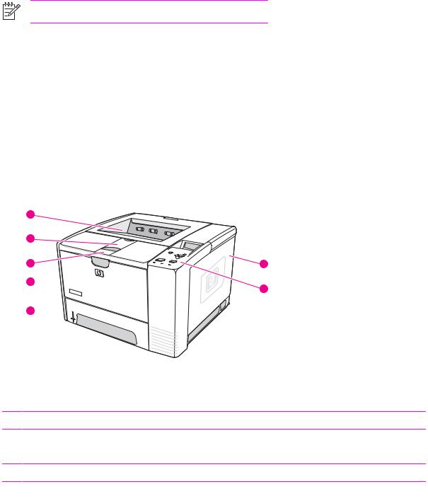
HP LaserJet 2400 Series printer base models
1 |
|
2 |
|
3 |
7 |
4 
6
5 
Figure 1-1 HP LaserJet 2400 Series printer base model, front/right-side view
1 Top output bin
2 Long-media extension
3 Cartridge-door latch
4 Tray 1
5 Tray 2
6 Control panel
7 Right-side cover
2 Chapter 1 Product Information |
ENWW |
 10
10
8 |
9 |
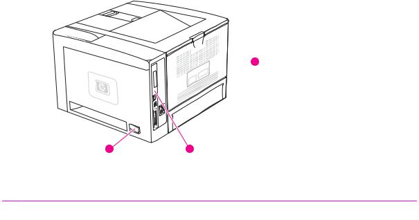
Figure 1-2 HP LaserJet 2400 Series printer base model, right-side/rear view
8 On/off switch
9 Interface ports
10 Rear output bin
ENWW |
Printer configurations 3 |

Features
The following tables describe the features of HP LaserJet 2400 Series printers.
Table 1-2 Speed
HP LaserJet 2410 printer |
HP LaserJet 2420 Series printer |
HP LaserJet 2430 Series printer |
Prints on letter-size paper at 25 pages per minute (ppm).
Prints on A4-size paper at 24 ppm.
Prints on letter-size paper at 30 pages per minute (ppm).
Prints on A4-size paper at 28 ppm.
Prints on letter-size paper at 35 pages per minute (ppm).
Prints on A4-size paper at 33 ppm.
Table 1-3 Resolution
HP LaserJet 2410 printer |
HP LaserJet 2420 Series printer |
FastRes 1200 produces 1200-dpi print quality for fast, high-quality printing of business text and graphics.
ProRes 1200 produces 1200-dpi printing for the best quality in line art and graphic images.
HP LaserJet print cartridges produce crisp, sharp output.
FastRes 1200 produces 1200-dpi print quality for fast, high-quality printing of business text and graphics.
ProRes 1200 produces 1200-dpi printing for the best quality in line art and graphic images.
HP LaserJet print cartridges produce crisp, sharp output.
HP LaserJet 2430 Series printer
FastRes 1200 produces 1200-dpi print quality for fast, high-quality printing of business text and graphics.
ProRes 1200 produces 1200-dpi printing for the best quality in line art and graphic images.
HP LaserJet print cartridges produce crisp, sharp output.
Table 1-4 Paper handling
HP LaserJet 2410 printer |
HP LaserJet 2420 Series printer |
Includes a 100-sheet manual-feed input tray and a 250-sheet input tray.
Compatible with an optional 500-sheet paper feeder.
Manual duplexing is available.
Includes a 100-sheet manual-feed input tray and a 250-sheet input tray.
Compatible with an optional 500-sheet paper feeder.
The HP LaserJet 2420d and 2420dn printers include a duplex-printing accessory (duplexer) for automatic twosided printing.
HP LaserJet 2430 Series printer
Includes a 100-sheet manual-feed input tray and a 250-sheet input tray.
The HP LaserJet 2430dtn printers include a duplex-printing accessory (duplexer) for automatic two-sided printing.
Table 1-5 Memory and processor
HP LaserJet 2410 printer |
HP LaserJet 2420 Series printer |
|
|
|
|
Includes 32 MB of RAM. |
The HP LaserJet 2420 printer includes |
|
Expandable up to 288 MB maximum |
32 MB of RAM, expandable to 288 MB |
|
maximum memory. |
||
memory. |
The HP LaserJet 2420d printer |
|
400-MHz processor speed. |
||
includes 48 MB RAM, expandable to |
||
|
304 MB maximum memory. |
HP LaserJet 2430 Series printer
The HP LaserJet 2430 printer includes 48 MB of RAM, expandable to 304 MB maximum memory.
The HP LaserJet 2430n printer includes 64 MB of RAM, expandable to 320 MB maximum memory.
4 Chapter 1 Product Information |
ENWW |
Table 1-5 Memory and processor (continued)
HP LaserJet 2410 printer |
HP LaserJet 2420 Series printer |
HP LaserJet 2430 Series printer |
The HP LaserJet 2420n and 2420dn printers include 64 MB RAM, expandable to 320 MB maximum memory.
400-MHz processor speed.
The HP LaserJet 2430t printer includes 48 MB of RAM, expandable to 304 MB maximum memory.
The HP LaserJet 2430tn and 2430dtn printers include 64 MB RAM, expandable to 320 MB maximum memory.
400-MHz processor speed.
Table 1-6 Interface connections and networking
HP LaserJet 2410 printer |
HP LaserJet 2420 Series printer |
HP LaserJet 2430 Series printer |
Includes a bidirectional, extended capabilities (ECP) type-B (IEEE 1284compliant) parallel connection.
Includes a USB 2.0 connection (full and high speed).
Includes one PCI-based enhanced input/output (EIO) expansion slot.
Includes a bidirectional, ECP type-B (IEEE 1284-compliant) parallel connection.
Includes a USB 2.0 connection (full and high speed).
Includes one PCI-based enhanced input/output (EIO) expansion slot.
Includes a bidirectional, ECP type-B (IEEE 1284-compliant) parallel connection.
Includes a USB 2.0 connection (full and high speed).
Includes one PCI-based enhanced input/output (EIO) expansion slot.
The HP LaserJet 2420n and 2420dn printers include an embedded
HP Jetdirect print server for connecting to a 10/100Base-TX network.
The HP LaserJet 2430n, 2430tn, and 2430dtn printers include an embedded HP Jetdirect print server for connecting to a 10/100Base-TX network.
NOTE 48 MB RAM is required for network connectivity for the HP LaserJet 2410, the HP LaserJet 2420, and the HP LaserJet 2430 printer base models.
Table 1-7 Language and fonts
HP LaserJet 2410 printer |
HP LaserJet 2420 Series printer |
HP LaserJet 2430 Series printer |
HP PCL6, PCL 5e, and HP PostScript® (PS) 3 emulation
80 fonts for Microsoft® Windows®
Additional fonts can be added by installing a CompactFlash font card.
HP PCL6, PCL 5e, and HP PostScript® (PS) 3 emulation
80 fonts for Microsoft® Windows®
Additional fonts can be added by installing a CompactFlash font card.
HP PCL6, PCL 5e, and HP PostScript® (PS) 3 emulation
80 fonts for Microsoft® Windows®
Additional fonts can be added by installing a CompactFlash font card.
Table 1-8 Print cartridge
HP LaserJet 2410 printer |
HP LaserJet 2420 Series printer |
HP LaserJet 2430 Series printer |
The standard print cartridge prints up to 6,000 pages. "Extended life" print cartridges print up to 12,000 pages.
The standard print cartridge prints up to 6,000 pages. "Extended life" print cartridges print up to 12,000 pages.
The standard print cartridge prints up to 6,000 pages. "Extended life" print cartridges print up to 12,000 pages.
ENWW |
Features 5 |

Table 1-8 Print cartridge (continued)
HP LaserJet 2410 printer |
HP LaserJet 2420 Series printer |
|
|
The HP smart-printing-supplies |
The HP smart-printing-supplies |
program automatically alerts when |
program automatically alerts when |
toner is low. |
toner is low. |
HP LaserJet 2430 Series printer
The HP smart-printing-supplies- program automatically alerts when toner is low.
Table 1-9 Energy savings
HP LaserJet 2410 printer |
HP LaserJet 2420 Series printer |
The printer automatically conserves electricity by reducing power consumption when it is not printing.
As an ENERGY STAR® partner, Hewlett-Packard Company has determined that this product meets ENERGY STAR® guidelines for energy efficiency.
The printer automatically conserves electricity by reducing power consumption when it is not printing.
As an ENERGY STAR® partner, Hewlett-Packard Company has determined that this product meets ENERGY STAR® guidelines for energy efficiency.
HP LaserJet 2430 Series printer
The printer automatically conserves electricity by reducing power consumption when it is not printing.
As an ENERGY STAR® partner, Hewlett-Packard Company has determined that this product meets ENERGY STAR® guidelines for energy efficiency.
Table 1-10 Economical printing
HP LaserJet 2410 printer |
HP LaserJet 2420 Series printer |
N-up printing (multiple pages on one sheet) saves paper.
Duplex printing (manual duplexing only) saves paper.
Printing in EconoMode saves toner.
N-up printing (multiple pages on one sheet) saves paper.
Duplex printing (manual duplexing, or automatic duplexing for models that include a duplexer) saves paper.
Printing in EconoMode saves toner.
HP LaserJet 2430 Series printer
N-up printing (multiple pages on one sheet) saves paper.
Duplex printing (manual duplexing, or automatic duplexing for models that include a duplexer) saves paper.
Printing in EconoMode saves toner.
Table 1-11 Accessibility
HP LaserJet 2410 printer |
HP LaserJet 2420 Series printer |
The online user guide is compatible with text screen-readers.
The print cartridge can be inserted and removed by using one hand.
All doors and covers can be opened by using one hand.
The 250-sheet input tray is easy to open and close.
All media-width guides can be adjusted by using one hand.
The online user guide is compatible with text screen-readers.
The print cartridge can be inserted and removed by using one hand.
All doors and covers can be opened by using one hand.
The 250-sheet input tray is easy to open and close.
All media-width guides can be adjusted by using one hand.
HP LaserJet 2430 Series printer
The online user guide is compatible with text screen-readers.
The print cartridge can be inserted and removed by using one hand.
All doors and covers can be opened by using one hand.
The 250-sheet and 500-sheet input trays are easy to open and close.
All media-width guides can be adjusted by using one hand.
6 Chapter 1 Product Information |
ENWW |

Specifications
Physical specifications
Table 1-12 Product dimensions
Product |
Height |
Depth |
Width |
Weight1 |
HP LaserJet 2410, 2420, 2420d, |
260 mm |
400 mm |
425 mm |
15.2 kg (33.5 lb) |
2420n, 2420dn, 2430, and 2430n |
(10.2 inches) |
(15.7 inches) |
(16.7 inches) |
|
|
|
|
|
|
HP LaserJet 2430t, 2430tn, and 2430dtn |
400 mm |
400 mm |
425 mm |
20.9 kg (46 lb) |
|
(15.7 inches) |
(15.7 inches) |
(16.7 inches) |
|
|
|
|
|
|
Optional 500-sheet feeder |
140 mm |
400 mm |
425 mm |
5.7 kg (12.5 lb) |
|
(5.5 inches) |
(15.7 inches) |
(15.7 inches) |
|
1 Without print cartridge
Table 1-13 Product dimensions, with all doors and trays fully opened
Printer model |
Height |
Depth |
Width |
|
|
|
|
HP LaserJet 2410, 2420, 2420d, 2420n, |
260 mm (10.2 inches) |
730 mm (28.7 inches) |
675 mm (26.6 inches) |
2420dn, 2430, and 2430n |
|
|
|
|
|
|
|
HP LaserJet 2430t, 2430tn, and 2430dtn |
400 mm (15.7 inches) |
730 mm (28.7 inches) |
675 mm (26.6 inches) |
|
|
|
|
Electrical specifications
WARNING! Power requirements are based on the country/region where the printer is sold. Do not convert operating voltages. This can damage the printer and void the product warranty.
Table 1-14 Power requirements
Specification |
110-volt models |
230-volt models |
|
|
|
Power requirements |
110 to 127 volts (± 10%) |
220 to 240 volts (± 10%) |
|
50/60 Hz (± 2 Hz) |
50/60 Hz (± 2 Hz) |
|
|
|
Rated short-term current |
10.0 Amps |
5.0 Amps |
|
|
|
|
|
|
Table 1-15 Power consumption (average, in watts)1
Product model |
Printing2 |
Ready |
Sleep |
Off |
|
|
|
|
|
HP LaserJet 2410 |
625 W3 |
11 W |
8.5 W |
0.4 W |
HP LaserJet 2420 |
625 W3 |
11 W |
8.5 W |
0.4 W |
|
|
|
|
|
HP LaserJet 2420d |
625 W3 |
11 W |
8.5 W |
0.4 W |
|
|
|
|
|
HP LaserJet 2420n |
625 W3 |
11 W |
8.5 W |
0.4 W |
|
|
|
|
|
HP LaserJet 2420dn |
625 W3 |
11 W |
8.5 W |
0.4 W |
|
|
|
|
|
ENWW |
Specifications 7 |

Table 1-15 Power consumption (average, in watts) (continued)
Product model |
Printing2 |
Ready |
Sleep |
Off |
HP LaserJet 2430 |
625 W3 |
11 W |
8.5 W |
0.4 W |
|
|
|
|
|
HP LaserJet 2430n |
625 W3 |
11 W |
8.5 W |
0.4 W |
|
|
|
|
|
HP LaserJet 2430t |
625 W3 |
11 W |
8.5 W |
0.4 W |
|
|
|
|
|
HP LaserJet 2430tn |
625 W3 |
11 W |
8.5 W |
0.4 W |
|
|
|
|
|
HP LaserJet 2430dtn |
625 W3 |
11 W |
8.5 W |
0.4 W |
1Values subject to change. See www.hp.com/support/lj2410, www.hp.com/support/lj2420, or www.hp.com/support/lj2430 for current information.
2Power numbers are the highest values measured using all standard voltages.
3HP LaserJet 2410 speed is 25 ppm on letter size and 24 ppm on A4 size. HP LaserJet 2420 speed is 30 ppm on letter size and 28 ppm on A4 size. HP LaserJet 2430 speed is 35 ppm on letter size and 33 ppm on A4 size.
Default time from Ready mode to Sleep = 30 minutes. The recovery time from Sleep to start of printing = less than 8.5 seconds.
Heat dissipation in Ready mode = 37.5 BTU/hour (HP LaserJet 2410), 37.5 BTU/hour (HP LaserJet 2420), and 37.5 BTU/hour (HP LaserJet 2430).
8 Chapter 1 Product Information |
ENWW |

Acoustic emissions
Table 1-16 Sound power and pressure level1 (HP LaserJet 2400 series)
Sound power level |
Declared per ISO 9296 |
|
|
|
|
Printing2 (HP LaserJet 2410) |
LWAd= 6.6 Bels (A) [66 dB(A)] |
|
|
|
|
Printing2 (HP LaserJet 2420) |
LWAd= 6.7 Bels (A) [67 dB(A)] |
|
|
|
|
Printing2 |
(HP LaserJet 2430) |
LWAd= 6.8 Bels (A) [68 dB(A)] |
|
|
|
Ready (HP LaserJet 2410) |
Essentially Inaudible |
|
|
|
|
Ready (HP LaserJet 2420) |
Essentially Inaudible |
|
|
|
|
Ready (HP LaserJet 2430) |
Essentially Inaudible |
|
|
|
|
Sound pressure level |
Declared per ISO 9296 |
|
|
|
|
Printing2 |
(HP LaserJet 2410) |
LpAm=52 dB (A) |
|
|
|
Printing2 |
(HP LaserJet 2420) |
LpAm=53 dB (A) |
|
|
|
Printing2 |
(HP LaserJet 2430) |
LpAm=53 dB (A) |
|
|
|
Ready (HP LaserJet 2410) |
Essentially Inaudible |
|
|
|
|
Ready (HP LaserJet 2420) |
Essentially Inaudible |
|
|
|
|
Ready (HP LaserJet 2430) |
Essentially Inaudible |
|
1Values subject to change. See www.hp.com/support/lj2410, www.hp.com/support/lj2420, or www.hp.com/support/lj2430 for current information.
2HP LaserJet 2410 speed is 24 ppm on A4 size. HP LaserJet 2420 speed is 28 ppm on A4 size. HP LaserJet 2430 speed is 33 ppm on A4 size.
3Configuration tested (HP LaserJet 2410): Base printer, simplex printing with A4 paper size.
4Configuration tested (HP LaserJet 2420): Base printer, simplex printing with A4 paper size.
5Configuration tested (HP LaserJet 2430): Base printer, simplex printing with A4 paper size.
Operating environment
Environmental condition |
Printing |
Storage/standby |
|
|
|
Temperature (printer and print cartridge) |
15° to 32.5°C (59° to 89°F) |
-20° to 40°C (-4° to 104°F) |
|
|
|
Relative humidity |
10% to 80% |
10% to 90% |
|
|
|
ENWW |
Specifications 9 |

Media specifications
The printer accepts a variety of media, such as cut-sheet paper, including up to 100% recycled fiber content paper; envelopes; labels; transparencies; and custom-size paper. Properties such as weight, composition, grain, and moisture content are important factors that affect printer performance and output quality. Media that does not meet the guidelines that are outlined in this manual can cause the following problems:
●Poor print quality
●Increased jams
●Premature wear on the printer, requiring repair
NOTE Some media might meet all of media specifications and still not produce satisfactory results. Improper handling, unacceptable temperature and humidity levels, and other variables over which Hewlett-Packard has no control can affect print quality. Before purchasing large quantities of media, make sure that it meets the requirements that are specified in the user guide and in theHP LaserJet Printer Family Print Media Guide, which is available for download at http://www.hp.com/support/ljpaperguide. Always test paper before buying large quantities.
CAUTION Using media that does not meet HP specifications can cause problems for the printer, requiring repair. This repair is not covered by the HP warranty or service agreements.
Supported types and sizes of print media
Column Tray 1 |
Dimensions1 |
Weight |
Capacity2 |
|
heading |
|
|
|
|
|
|
|
|
|
Minimum size (custom) |
76 x 127 mm |
60 to 199 g/m2 (16 to 53 lb) |
100 sheets of 75 g/m2 |
|
|
(3 x 5 inches) |
|
(20 lb) paper |
|
|
|
|
|
|
Maximum size |
216 x 356 mm |
|
|
|
(custom) |
(8.5 x 14 inches) |
|
|
|
|
|
|
|
|
Transparency |
(Same as preceding |
Thickness: 0.10 to 0.14 mm |
75 typical |
|
|
minimum and |
(0.0039 to 0.0055 inch) |
|
|
|
maximum paper sizes.) |
|
|
|
Labels3 |
Thickness: 0.10 to 0.14 mm (0.0039 to 0.005 |
50 typical |
||
|
||||
|
|
inch) |
|
|
|
|
|
|
|
Envelopes |
|
Up to 90 g/m2 (16 to 24 lb) |
Up to 10 |
1The printer supports a wide range of sizes. See the printer software for supported sizes. To print on custom-size paper, see the user guide.
2Capacity can vary depending on media weight and thickness, as well as on environmental conditions.
3Smoothness: 100 to 250 (Sheffield)
NOTE You might experience some jams when using any media that is less than
178 mm (7 inches) long. These jams might be caused by media that has been affected by environmental conditions. For optimum performance, make sure that you are storing and handling the media correctly (see Printing and paper storage environment on page 12).
Tray 2 (250-sheet tray) and |
Dimensions1 |
Weight |
Capacity2 |
tray 3 (500-sheet tray) |
|
|
|
|
|
|
|
10 Chapter 1 Product Information |
ENWW |

Letter |
216 x 279 mm |
|
(8.5 x 11 inches) |
|
|
A4 |
210 x 297 mm |
|
(8.3 x 11.7 inches) |
|
|
Executive |
191 x 267 mm |
|
(7.3 x 10.5 inches) |
|
|
Legal |
216 x 356 mm |
|
(8.5 x 14 inches) |
|
|
B5 (JIS) |
182 x 257 mm |
|
(7.2 x 10 inches) |
|
|
A5 |
148 x 210 mm |
|
(5.8 x 8.3 inches) |
|
|
8.5 x 13 inches |
216 x 330 mm |
|
(8.5 x 13 inches) |
60 to 120 g/m2 (16 to 32 lb) |
250 sheets of 75 g/m2 |
|
(20 lb) media |
1The printer supports a wide range of sizes. See the printer software for supported sizes. To print on custom-size paper, see the user guide.
2Capacity can vary depending on media weight and thickness, as well as on environmental conditions.
Built-in duplexer1 |
Dimensions2 |
Weight |
Letter |
216 x 279 mm (8.5 x 11 inches) |
60 to 105 g/m2 (16 to 28 lb Bond) |
A4 |
210 x 297 mm (8.3 x 11.7 inches) |
|
|
|
|
Legal |
216 x 356 mm (8.5 x 14 inches) |
|
|
|
|
8.5 x 13 inches |
216 x 330 mm (8.5 x 13 inches) |
|
1The built-in duplexer is included only with the HP LaserJet 2420d, 2420dn, and 2430dtn printers.
2The printer supports a wide range of sizes. See the printer software for supported sizes. To print on custom-size paper, see the user guide.
NOTE Prepunched media is not supported for automatic duplexing.
For more information about using print media, see the user guide.
Paper and print media
For complete media specifications for all HP LaserJet printers, see the HP LaserJet Printer Family Print Media Guide (available at http://www.hp.com/support/ljpaperguide).
Category |
Specifications |
|
|
Acid content |
5.5 pH to 8.0 pH |
|
|
Caliper |
0.094 to 0.18 mm (3.0 to 7.0 mils) |
|
|
ENWW |
Media specifications 11 |

Category |
Specifications |
|
|
Curl in ream |
Flat within 5 mm (0.02 inch) |
|
|
Cut edge conditions |
Cut with sharp blades with no visible fray |
|
|
Fusing compatibility |
Must not scorch, melt, offset, or release hazardous |
|
emissions when heated to 200°C (392°F) for 0.1 second |
|
|
Grain |
Long grain |
|
|
Moisture content |
4% to 6% by weight |
|
|
Smoothness |
100 to 250 Sheffield |
|
|
Printing and paper storage environment
Ideally, the printing and paper storage environment should be at or near room temperature, and not too dry or too humid. Remember paper is hygroscopic; it absorbs and loses moisture rapidly.
Heat works with humidity to damage paper. Heat causes the moisture in paper to evaporate, while cold causes it to condense on the sheets. Heating systems and air conditioners remove most of the humidity from a room. As paper is opened and used, it loses moisture, causing streaks and smudging. Humid weather or water coolers can cause the humidity to increase in a room. As paper is opened and used it absorbs any excess moisture, causing light print and dropouts. Also, as paper loses and gains moisture it can distort. This can cause jams.
As a result, paper storage and handling are as important as the paper-making process itself. Paper storage environmental conditions directly affect the feed operation.
Care should be taken not to purchase more paper than can be easily used in a short time (about 3 months). Paper stored for long periods might experience heat and moisture extremes, which can cause damage. Planning is important to prevent damage to a large supply of media.
Unopened paper in sealed reams can remain stable for several months before use. Opened packages of media have more potential for environmental damage, especially if they are not wrapped with a moisture-proof barrier.
The paper storage environment should be properly maintained to ensure optimum printer performance. The required condition is 20° to 24°C (68° to 75°F), with a relative humidity of 45% to 55%. The following guidelines should be helpful when evaluating the paper's storage environment:
●Paper should be stored at or near room temperature.
●The air should not be too dry or too humid (due to the hygroscopic properties of paper).
●The best way to store an opened ream of media is to rewrap it tightly in its moisture-proof wrapping. If the printer environment is subject to extremes, unwrap only the amount of media to be used during the day's operation to prevent unwanted moisture changes.
Envelopes
Envelope construction is critical. Envelope fold lines can vary considerably, not only between manufacturers, but also within a box from the same manufacturer. Successful printing on envelopes
12 Chapter 1 Product Information |
ENWW |
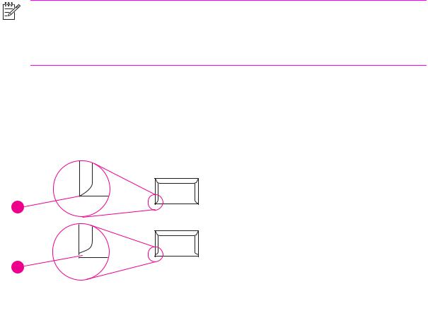
depends upon the quality of the envelopes. When selecting envelopes, consider the following components:
●Weight: The weight of the envelope paper should not exceed 105 g/m2 (28 lb) or jamming might occur.
●Construction: Prior to printing, envelopes should lie flat with less than 6 mm (0.25 inch) curl, and should not contain air.
●Condition:Envelopes should not be wrinkled, nicked, or otherwise damaged.
●Temperature: You should use envelopes that are compatible with the heat and pressure of the printer.
●Size: You should use only envelopes within the following size ranges.
●Minimum: 76 x 127 mm (3 x 5 inches)
●Maximum: 216 x 356 mm (8.5 x 14 inches)
NOTE Use only tray 1 to print envelopes. You might experience some jams when using any media with a length less than 178 mm (7 inches). This might be caused by paper that has been affected by environmental conditions. For optimum performance, make sure you are storing and handling the paper correctly (see Printing and paper storage environment
on page 12). Choose envelopes in the printer driver (see Printer drivers on page 25).
Envelopes with double side seams
Double side-seam construction has vertical seams at both ends of the envelope rather than diagonal seams. This style might be more likely to wrinkle. Be sure the seam extends all the way to the corner of the envelope as illustrated below.
1 
2
1 Acceptable envelope construction
2 Unacceptable envelope construction
ENWW |
Media specifications 13 |

Envelopes with adhesive strips or flaps
Envelopes with a peel-off adhesive strip or with more than one flap that folds over to seal must use adhesives compatible with the heat and pressure in the printer. The extra flaps and strips might cause wrinkling, creasing, or even jams and might even damage the fuser.
Envelope margins
The following gives typical address margins for a commercial #10 or DL envelope.
Type of address |
Top margin |
Left margin |
|
|
|
Return address |
15 mm (0.6 inch) |
15 mm (0.6 inch) |
|
|
|
Delivery address |
51 mm (2 inches) |
89 mm (3.5 inches) |
|
|
|
|
|
|
NOTE For the best print quality, position margins no closer than 15 mm (0.6 inch) from the edges of the envelope. Avoid printing over the area where the envelope seams meet.
Envelope storage
Proper storage of envelopes helps contribute to print quality. Envelopes should be stored flat. If air is trapped in an envelope, creating an air bubble, then the envelope might wrinkle during printing.
Labels
CAUTION To avoid damaging the printer, use only labels recommended for laser printers. To prevent serious jams, always use tray 1 to print labels and always use the rear output bin. Never print on the same sheet of labels more than once or print on a partial sheet of labels.
When selecting labels, consider the quality of each component:
●Adhesives: The adhesive material should be stable at 200°C (392°F), the printer fusing temperature.
●Arrangement: Only use labels with no exposed backing between them. Labels can peel off sheets with spaces between the labels, causing serious jams.
●Curl: Prior to printing, labels must lie flat with no more than 13 mm (0.5 inch) of curl in any direction.
●Condition: Do not use labels with wrinkles, bubbles, or other indications of separation.
Transparencies
Transparencies used in the printer must be able to withstand 200°C (392°F), the printer's fusing temperature.
CAUTION To avoid damaging the printer, use only transparencies recommended for use in HP LaserJet printers, such as HP-brand transparencies. (For ordering information, see Ordering parts and supplies on page 218.)
14 Chapter 1 Product Information |
ENWW |
Loading...