


 Loading...
LASERJET PRO M1530
MFP SERIES
Service Manual

HP LaserJet Pro M1530 MFP Series
Service Manual
Copyright and License
© 2010 Copyright Hewlett-Packard
Development Company, L.P.
Reproduction, adaptation, or translation without prior written permission is prohibited, except as allowed under the copyright laws.
The information contained herein is subject to change without notice.
The only warranties for HP products and services are set forth in the express warranty statements accompanying such products and services. Nothing herein should be construed as constituting an additional warranty. HP shall not be liable for technical or editorial errors or omissions contained herein.
Part number: CE538-90986
Edition 1, 9/2010
Trademark Credits
Microsoft®, Windows®, Windows® XP, and Windows Vista® are U.S. registered trademarks of Microsoft Corporation.
ENERGY STAR and the ENERGY STAR mark are registered U.S. marks.

Conventions used in this guide
TIP: Tips provide helpful hints or shortcuts.
 NOTE: Notes provide important information to explain a concept or to complete a task.
 CAUTION: Cautions indicate procedures that you should follow to avoid losing data or damaging the product.
 WARNING! Warnings alert you to specific procedures that you should follow to avoid personal injury, catastrophic loss of data, or extensive damage to the product.
ENWW |
iii |

Table of contents
1 Removal and replacement ............................................................................................................................. |
1 |
Introduction ........................................................................................................................................... |
2 |
Removal and replacement strategy ...................................................................................................... |
2 |
Electrostatic discharge ......................................................................................................................... |
3 |
Required tools ...................................................................................................................................... |
3 |
Service approach ................................................................................................................................. |
3 |
Before performing service .................................................................................................... |
3 |
After performing service ....................................................................................................... |
4 |
Post-service test .................................................................................................................. |
4 |
Print-quality test .................................................................................................. |
4 |
Parts removal order ............................................................................................................. |
4 |
Removal and replacement procedures ................................................................................................ |
7 |
Print cartridge ...................................................................................................................... |
7 |
Pickup roller ......................................................................................................................... |
8 |
Separation pad .................................................................................................................... |
9 |
Transfer roller .................................................................................................................... |
10 |
Covers ............................................................................................................................... |
10 |
Main tray ........................................................................................................... |
10 |
Output bin extension ......................................................................................... |
11 |
Left cover .......................................................................................................... |
12 |
Remove the left cover ....................................................................... |
12 |
Scanner assembly ............................................................................................. |
15 |
Remove the scanner assembly ........................................................ |
15 |
Scanner hinges ................................................................................................. |
17 |
Right cover ........................................................................................................ |
19 |
Remove the right cover .................................................................... |
19 |
Duplex door ....................................................................................................... |
22 |
Duplex frame ..................................................................................................... |
23 |
Remove the duplex frame ................................................................ |
23 |
Cartridge door ................................................................................................... |
24 |
Remove the cartridge door ............................................................... |
24 |
Front cover ........................................................................................................ |
27 |
Remove the front cover .................................................................... |
27 |
Upper cover ....................................................................................................... |
28 |
ENWW |
v |
Remove the upper cover .................................................................. |
28 |
Main assemblies ................................................................................................................ |
29 |
Formatter PCA .................................................................................................. |
29 |
Remove the formatter PCA .............................................................. |
29 |
Fax PCA ............................................................................................................ |
31 |
Remove the fax PCA ........................................................................ |
31 |
Laser scanner assembly ................................................................................... |
32 |
Remove the laser scanner assembly ............................................... |
32 |
Reinstall the laser scanner assembly ............................................... |
35 |
Pickup assembly ............................................................................................... |
36 |
Remove the pickup assembly ........................................................... |
36 |
Reinstall the pickup assembly .......................................................... |
41 |
Fuser ................................................................................................................. |
43 |
Remove the fuser ............................................................................. |
43 |
Reinstall the fuser ............................................................................. |
48 |
Main motor ........................................................................................................ |
49 |
Remove the main motor ................................................................... |
49 |
Reinstall the main motor drive belt ................................................... |
54 |
Pickup solenoid ................................................................................................. |
55 |
Remove the pickup solenoid ............................................................ |
55 |
Engine controller PCA ....................................................................................... |
59 |
Remove the engine controller PCA .................................................. |
59 |
Reinstall the engine controller PCA .................................................. |
64 |
Duplex reverse solenoid .................................................................................... |
67 |
Remove the duplex reverse solenoid ............................................... |
67 |
Main fan ............................................................................................................ |
70 |
Remove the main fan ....................................................................... |
70 |
Reinstall the main fan ....................................................................... |
73 |
Duplex connector PCA ...................................................................................... |
74 |
Remove the duplex connector PCA ................................................. |
74 |
Scanner components ......................................................................................................... |
77 |
Document feeder input tray ............................................................................... |
77 |
Document feeder cover ..................................................................................... |
78 |
Document feeder pick arm assembly ................................................................ |
80 |
Remove the document feeder pick arm assembly ........................... |
80 |
Document feeder core assembly ...................................................................... |
82 |
Remove the document feeder core assembly .................................. |
82 |
Post scan pinch rollers ...................................................................................... |
84 |
Remove the post scan pinch rollers ................................................. |
84 |
Document feeder base assembly ...................................................................... |
85 |
Remove the document feeder base assembly ................................. |
85 |
Document feeder floating hinges ...................................................................... |
87 |
Remove the document feeder floating hinges .................................. |
87 |
Control panel ..................................................................................................... |
88 |
vi |
ENWW |
2 Solve problems ............................................................................................................................................. |
89 |
Problem-solving checklist ................................................................................................................... |
90 |
Step 1: Check that the product power is on ....................................................................... |
90 |
Step 2: Check the control panel for error messages ......................................................... |
90 |
Step 3: Test print functionality ........................................................................................... |
90 |
Step 4: Test copy functionality ........................................................................................... |
91 |
Step 5: Test the fax sending functionality .......................................................................... |
91 |
Step 6: Test the fax receiving functionality ........................................................................ |
91 |
Step 7: Try sending a print job from a computer ................................................................ |
91 |
Menu map .......................................................................................................................................... |
92 |
Troubleshooting process .................................................................................................................... |
93 |
Determine the problem source .......................................................................................... |
93 |
Power subsystem .............................................................................................................. |
94 |
Power-on checks ............................................................................................... |
94 |
Tools for troubleshooting .................................................................................................................... |
95 |
Individual component diagnostics ...................................................................................... |
95 |
Engine diagnostics ............................................................................................ |
95 |
Engine test button ............................................................................. |
95 |
Components tests ............................................................................................. |
96 |
Drum rotation functional check ........................................................ |
96 |
Half self-test functional check ........................................................... |
96 |
Diagrams ........................................................................................................................... |
97 |
Plug/jack locations ............................................................................................ |
97 |
Location of connectors ...................................................................................... |
98 |
Locations of major components ...................................................................... |
100 |
General timing charts ...................................................................................... |
104 |
General circuit diagram ................................................................................... |
105 |
HP ToolboxFX ................................................................................................................. |
106 |
View HP ToolboxFX ........................................................................................ |
106 |
Status .............................................................................................................. |
106 |
Event log ......................................................................................... |
106 |
Fax .................................................................................................................. |
107 |
Fax tasks ........................................................................................ |
107 |
Fax phone book .............................................................................. |
107 |
Fax send log ................................................................................... |
109 |
Fax receive log ............................................................................... |
109 |
Block Faxes .................................................................................... |
109 |
Help ................................................................................................................. |
109 |
System Settings .............................................................................................. |
110 |
Device information .......................................................................... |
110 |
Paper handling ............................................................................... |
111 |
Print quality ..................................................................................... |
111 |
Paper types .................................................................................... |
111 |
System setup .................................................................................. |
112 |
ENWW |
vii |
Service ............................................................................................ |
112 |
Device polling ................................................................................. |
112 |
Print Settings ................................................................................................... |
112 |
Printing ........................................................................................... |
112 |
PCL 5e ............................................................................................ |
113 |
PostScript ....................................................................................... |
113 |
Network Settings ............................................................................................. |
113 |
Internal print quality test pages ........................................................................................ |
114 |
Print a cleaning page ...................................................................................... |
114 |
Configuration page .......................................................................................... |
114 |
Print quality troubleshooting tools .................................................................................... |
115 |
Repetitive defect ruler ..................................................................................... |
115 |
Control panel menus ........................................................................................................ |
115 |
Setup menu ..................................................................................................... |
115 |
Quick Forms menu ......................................................................... |
116 |
Reports menu ................................................................................. |
116 |
Fax Setup ....................................................................................... |
117 |
System Setup menu ....................................................................... |
119 |
Service menu .................................................................................. |
121 |
Network Setup menu ...................................................................... |
122 |
Function-specific menus ................................................................................. |
122 |
Copy ............................................................................................... |
123 |
Fax .................................................................................................. |
124 |
Interpret control panel messages .................................................................................... |
126 |
Control panel message types .......................................................................... |
126 |
Control panel messages ................................................................................. |
126 |
Paper feeds incorrectly or becomes jammed ................................................................................... |
143 |
The product does not pick up paper ................................................................................ |
143 |
The product picks up multiple sheets of paper ................................................................ |
143 |
Prevent paper jams .......................................................................................................... |
143 |
Clear jams ........................................................................................................................ |
144 |
Jam locations .................................................................................................. |
144 |
Clear jams from the document feeder ............................................................. |
145 |
Clear jams from the input trays ....................................................................... |
146 |
Clear jams from inside the product ................................................................. |
148 |
Clear jams from the output areas .................................................................... |
150 |
Clear jams from the duplexer .......................................................................... |
151 |
Improve print quality ......................................................................................................................... |
154 |
Select a paper type .......................................................................................................... |
154 |
Use paper that meets HP specifications .......................................................................... |
154 |
Print a cleaning page ....................................................................................................... |
155 |
Check the print cartridge .................................................................................................. |
155 |
Print the Supplies Status page ........................................................................ |
156 |
Inspect the print cartridge for damage ............................................................ |
157 |
viii |
ENWW |
Repeating defects ........................................................................................... |
157 |
Use the printer driver that best meets your printing needs .............................................. |
158 |
Improve print quality for copies ........................................................................................ |
158 |
Clean the product ............................................................................................................................. |
160 |
Clean the pickup roller ..................................................................................................... |
160 |
Clean the document feeder pickup rollers and separation pad ....................................... |
161 |
Clean the paper path ....................................................................................................... |
162 |
Clean the paper path from HP ToolboxFX ...................................................... |
162 |
Clean the paper path from the control panel ................................................... |
162 |
Clean the scanner glass strip and platen ......................................................................... |
162 |
The product does not print or it prints slowly .................................................................................... |
164 |
The product does not print ............................................................................................... |
164 |
The product prints slowly ................................................................................................. |
164 |
Solve connectivity problems ............................................................................................................. |
166 |
Solve direct-connect problems ........................................................................................ |
166 |
Solve network problems .................................................................................................. |
166 |
Poor physical connection ................................................................................ |
166 |
The computer is using the incorrect IP address for the product ...................... |
166 |
The computer is unable to communicate with the product .............................. |
167 |
The product is using incorrect link and duplex settings for the network .......... |
167 |
New software programs might be causing compatibility problems ................. |
167 |
The computer or workstation might be set up incorrectly ................................ |
167 |
The product is disabled, or other network settings are incorrect ..................... |
167 |
Service mode functions .................................................................................................................... |
168 |
Secondary service menu ................................................................................................. |
168 |
Open the secondary service menu ................................................................. |
168 |
Secondary service menu structure .................................................................. |
168 |
Product resets .................................................................................................................. |
169 |
Solve fax problems ........................................................................................................................... |
169 |
Fax troubleshooting checklist .......................................................................................... |
169 |
Troubleshoot fax codes and trace reports ....................................................................... |
171 |
View and interpret fax error codes .................................................................. |
171 |
View the fax trace report ................................................................................. |
172 |
Fax logs and reports ........................................................................................................ |
173 |
Print all fax reports .......................................................................................... |
173 |
Print individual fax reports ............................................................................... |
173 |
Set the fax activity log to print automatically ................................................... |
174 |
Set the fax error report .................................................................................... |
174 |
Set the fax confirmation report ........................................................................ |
175 |
Include the first page of each fax on the fax confirmation, fax error, and last |
|
call reports ....................................................................................................... |
176 |
Change error correction and fax speed ........................................................................... |
176 |
Set the fax-error-correction mode ................................................................... |
176 |
Change the fax speed ..................................................................................... |
176 |
ENWW |
ix |
Solve problems sending faxes ......................................................................................... |
177 |
An error message displays on the control panel ............................................. |
177 |
The Comm. Error message appears .............................................. |
177 |
No dial tone .................................................................................... |
178 |
The Fax is busy message appears ................................................. |
178 |
The No fax answer message appears ............................................ |
179 |
Document feeder paper jam ........................................................... |
179 |
The Fax memory full message appears ......................................... |
179 |
Scanner error .................................................................................. |
180 |
The control panel displays a Ready message with no attempt to send the fax |
180 |
The control panel displays the message "Storing page 1" and does not |
|
progress beyond that message ....................................................................... |
180 |
Faxes can be received, but not sent ............................................................... |
180 |
Unable to use fax functions from the control panel ......................................... |
181 |
Unable to use speed dials ............................................................................... |
181 |
Unable to use group dials ............................................................................... |
181 |
Receive a recorded error message from the phone company when trying to |
|
send a fax ........................................................................................................ |
182 |
Unable to send a fax when a phone is connected to the product ................... |
182 |
Solve problems receiving faxes ....................................................................................... |
183 |
The fax does not respond ............................................................................... |
183 |
The fax has a dedicated phone line ................................................ |
183 |
An answering machine is connected to the product ....................... |
183 |
A telephone handset is connected to the product .......................... |
184 |
The Answer Mode setting is set to the Manual setting ................... |
184 |
Voice mail is available on the fax line ............................................. |
184 |
The product is connected to a DSL phone service ......................... |
185 |
The product uses a fax over IP or VoIP phone service .................. |
185 |
An error message displays on the control panel ............................................. |
185 |
The No fax detected message appears .......................................... |
185 |
The Comm. Error message appears .............................................. |
186 |
The Fax memory full message appears ......................................... |
186 |
The Fax is busy message appears ................................................. |
187 |
A fax is received but does not print ................................................................. |
187 |
The Private Receive feature is on .................................................. |
187 |
The Receive to PC feature is enabled ............................................ |
187 |
Sender receives a busy signal ........................................................................ |
188 |
A handset is connected to the product ........................................... |
188 |
A phone line splitter is being used .................................................. |
188 |
No dial tone ..................................................................................................... |
188 |
Cannot send or receive a fax on a PBX line ................................................... |
188 |
Solve general fax problems ............................................................................................. |
189 |
Faxes are sending slowly ................................................................................ |
189 |
Fax quality is poor ........................................................................................... |
190 |
x |
ENWW |
Fax cuts off or prints on two pages ................................................................. |
190 |
Product updates ............................................................................................................................... |
191 |
3 Parts and diagrams ..................................................................................................................................... |
193 |
Order parts by authorized service providers .................................................................................... |
194 |
Order replacement parts .................................................................................................. |
194 |
Related documentation and software .............................................................................. |
194 |
Supplies part numbers ..................................................................................................... |
194 |
Whole unit replacement part numbers ............................................................................. |
194 |
Customer self repair parts ............................................................................................... |
195 |
Service parts .................................................................................................................... |
195 |
How to use the parts lists and diagrams .......................................................................................... |
195 |
Assembly locations ........................................................................................................................... |
196 |
Locations of major components ....................................................................................... |
196 |
Covers .............................................................................................................................................. |
200 |
Internal assemblies .......................................................................................................................... |
202 |
Internal assemblies (1 of 4) ............................................................................................. |
202 |
Internal assemblies (2 of 4) ............................................................................................. |
204 |
Internal assemblies (3 of 4) ............................................................................................. |
206 |
Internal assemblies (4 of 4) ............................................................................................. |
208 |
Scanner and document feeder (ADF) main assemblies ................................................................... |
210 |
Document feeder internal components ............................................................................................ |
212 |
Alphabetical parts list ....................................................................................................................... |
214 |
Numerical parts list ........................................................................................................................... |
217 |
Appendix A Service and support ................................................................................................................. |
221 |
Hewlett-Packard limited warranty statement .................................................................................... |
222 |
HP's Premium Protection Warranty: LaserJet print cartridge limited warranty statement ................ |
223 |
Data stored on the print cartridge ..................................................................................................... |
224 |
End User License Agreement .......................................................................................................... |
225 |
Customer support ............................................................................................................................. |
227 |
Repack the product .......................................................................................................................... |
228 |
Appendix B Product specifications ............................................................................................................. |
229 |
Physical specifications ..................................................................................................................... |
230 |
Power consumption .......................................................................................................................... |
230 |
Acoustic specifications ..................................................................................................................... |
230 |
Environmental specifications ............................................................................................................ |
230 |
Appendix C Regulatory information ............................................................................................................ |
231 |
FCC regulations ............................................................................................................................... |
232 |
Environmental product stewardship program ................................................................................... |
233 |
Protecting the environment .............................................................................................. |
233 |
ENWW |
xi |
Ozone production ............................................................................................................ |
233 |
Power consumption ......................................................................................................... |
233 |
Toner consumption .......................................................................................................... |
233 |
Paper use ........................................................................................................................ |
233 |
Plastics ............................................................................................................................ |
233 |
HP LaserJet print supplies ............................................................................................... |
233 |
Return and recycling instructions ..................................................................................... |
234 |
United States and Puerto Rico ........................................................................ |
234 |
Multiple returns (more than one cartridge) ..................................... |
234 |
Single returns ................................................................................. |
234 |
Shipping .......................................................................................... |
234 |
Non-U.S. returns ............................................................................................. |
235 |
Paper ............................................................................................................................... |
235 |
Material restrictions .......................................................................................................... |
235 |
Disposal of waste equipment by users in private households in the European Union .... |
235 |
Chemical substances ....................................................................................................... |
236 |
Material Safety Data Sheet (MSDS) ................................................................................ |
236 |
For more information ....................................................................................................... |
236 |
Declaration of conformity .................................................................................................................. |
237 |
Certificate of Volatility ....................................................................................................................... |
239 |
Safety statements ............................................................................................................................. |
240 |
Laser safety ..................................................................................................................... |
240 |
Canadian DOC regulations .............................................................................................. |
240 |
VCCI statement (Japan) .................................................................................................. |
240 |
Power cord instructions ................................................................................................... |
240 |
Power cord statement (Japan) ......................................................................................... |
240 |
EMC statement (Korea) ................................................................................................... |
240 |
Laser statement for Finland ............................................................................................. |
241 |
GS statement (Germany) ................................................................................................. |
241 |
Substances Table (China) ............................................................................................... |
242 |
Restriction on Hazardous Substances statement (Turkey) ............................................. |
242 |
Additional statements for telecom (fax) products ............................................................................. |
243 |
EU Statement for Telecom Operation .............................................................................. |
243 |
New Zealand Telecom Statements .................................................................................. |
243 |
Additional FCC statement for telecom products (US) ...................................................... |
243 |
Telephone Consumer Protection Act (US) ...................................................................... |
244 |
Industry Canada CS-03 requirements ............................................................................. |
244 |
Index ................................................................................................................................................................. |
247 |
xii |
ENWW |

List of tables
Table 2-1 Secondary Service menu ............................................................................................................... |
168 |
|
Table 3-1 Order parts, accessories, and supplies .......................................................................................... |
194 |
|
Table 3-2 Related documentation and software ............................................................................................ |
194 |
|
Table 3-3 Supplies part numbers ................................................................................................................... |
194 |
|
Table 3-4 Whole unit replacement part numbers ........................................................................................... |
194 |
|
Table 3-5 Customer replaceable units (CRU) kit part numbers ..................................................................... |
195 |
|
Table 3-6 |
Service parts .................................................................................................................................. |
195 |
Table 3-7 Locations of major components ..................................................................................................... |
196 |
|
Table 3-8 Rollers, solenoids, and fan ............................................................................................................. |
197 |
|
Table 3-9 |
Cross-sectional view ...................................................................................................................... |
199 |
Table 3-10 Print engine covers ...................................................................................................................... |
201 |
|
Table 3-11 Internal assemblies (1 of 4) .......................................................................................................... |
203 |
|
Table 3-12 Internal assemblies (2 of 4) .......................................................................................................... |
205 |
|
Table 3-13 Internal assemblies (3 of 4) .......................................................................................................... |
207 |
|
Table 3-14 Internal assemblies (4 of 4) .......................................................................................................... |
209 |
|
Table 3-15 Scanner and document feeder main assemblies ......................................................................... |
211 |
|
Table 3-16 Document feeder assembly parts ................................................................................................ |
213 |
|
Table 3-17 Alphabetical parts list ................................................................................................................... |
214 |
|
Table 3-18 Numerical parts list ....................................................................................................................... |
217 |
|
Table B-1 |
Physical specifications1 .................................................................................................................. |
230 |
Table B-2 HP LaserJet Pro M1530 MFP Series (average in watts)12 ............................................................ |
230 |
|
Table B-3 HP LaserJet Pro M1530 MFP Series12 .......................................................................................... |
230 |
|
Table B-4 |
Environmental specifications ......................................................................................................... |
230 |
ENWW |
xiii |

List of figures
Figure 1-1 Phillips and Pozidriv screwdriver comparison ................................................................................... |
3 |
Figure 1-2 Parts removal order: Scanner and document feeder ........................................................................ |
5 |
Figure 1-3 Parts removal order: Product base ................................................................................................... |
6 |
Figure 1-4 Remove the print cartridge (1 of 2) ................................................................................................... |
7 |
Figure 1-5 Remove the print cartridge (2 of 2) ................................................................................................... |
7 |
Figure 1-6 Remove the pickup roller (1 of 2) ...................................................................................................... |
8 |
Figure 1-7 Remove the pickup roller (2 of 2) ...................................................................................................... |
8 |
Figure 1-8 Remove the separation pad assembly ............................................................................................. |
9 |
Figure 1-9 Remove the transfer roller .............................................................................................................. |
10 |
Figure 1-10 Remove the tray ............................................................................................................................ |
10 |
Figure 1-11 Remove the output bin extension ................................................................................................. |
11 |
Figure 1-12 Remove the left cover (1 of 5) ....................................................................................................... |
12 |
Figure 1-13 Remove the left cover (2 of 5) ....................................................................................................... |
12 |
Figure 1-14 Remove the left cover (3 of 5) ....................................................................................................... |
13 |
Figure 1-15 Remove the left cover (4 of 5) ....................................................................................................... |
13 |
Figure 1-16 Remove the left cover (5 of 5) ....................................................................................................... |
14 |
Figure 1-17 Remove the scanner assembly (1 of 5) ........................................................................................ |
15 |
Figure 1-18 Remove the scanner assembly (2 of 5) ........................................................................................ |
15 |
Figure 1-19 Remove the scanner assembly (3 of 5) ........................................................................................ |
16 |
Figure 1-20 Remove the scanner assembly (4 of 5) ........................................................................................ |
16 |
Figure 1-21 Remove the scanner assembly (5 of 5) ........................................................................................ |
17 |
Figure 1-22 Remove the scanner hinges (1 of 2) ............................................................................................. |
17 |
Figure 1-23 Remove the scanner hinges (2 of 2) ............................................................................................. |
18 |
Figure 1-24 Remove the right cover (1 of 5) .................................................................................................... |
19 |
Figure 1-25 Remove the right cover (2 of 5) .................................................................................................... |
19 |
Figure 1-26 Remove the right cover (3 of 5) .................................................................................................... |
20 |
Figure 1-27 Remove the right cover (4 of 5) .................................................................................................... |
20 |
Figure 1-28 Remove the right cover (5 of 5) .................................................................................................... |
21 |
Figure 1-29 Remove the duplex door ............................................................................................................... |
22 |
Figure 1-30 Remove the duplex frame (1 of 2) ................................................................................................ |
23 |
Figure 1-31 Remove the duplex frame (2 of 2) ................................................................................................ |
23 |
Figure 1-32 Remove the cartridge door (1 of 5) ............................................................................................... |
24 |
Figure 1-33 Remove the cartridge door (2 of 5) ............................................................................................... |
25 |
Figure 1-34 Remove the cartridge door (3 of 5) ............................................................................................... |
25 |
ENWW |
xv |
Figure 1-35 Remove the cartridge door (4 of 5) ............................................................................................... |
26 |
Figure 1-36 Remove the cartridge door (5 of 5) ............................................................................................... |
26 |
Figure 1-37 Remove the front cover ................................................................................................................. |
27 |
Figure 1-38 Remove the upper cover ............................................................................................................... |
28 |
Figure 1-39 Remove the formatter PCA (1 of 2) .............................................................................................. |
29 |
Figure 1-40 Remove the formatter PCA (2 of 2) .............................................................................................. |
30 |
Figure 1-41 Remove the fax PCA .................................................................................................................... |
31 |
Figure 1-42 Remove the laser scanner assembly (1 of 5) ............................................................................... |
32 |
Figure 1-43 Remove the laser scanner assembly (2 of 5) ............................................................................... |
33 |
Figure 1-44 Remove the laser scanner assembly (3 of 5) ............................................................................... |
33 |
Figure 1-45 Remove the laser scanner assembly (4 of 5) ............................................................................... |
34 |
Figure 1-46 Remove the laser scanner assembly (5 of 5) ............................................................................... |
34 |
Figure 1-47 Reinstall the laser scanner assembly ........................................................................................... |
35 |
Figure 1-48 Remove the pickup assembly (1 of 9) ........................................................................................... |
36 |
Figure 1-49 Remove the pickup assembly (2 of 9) ........................................................................................... |
37 |
Figure 1-50 Remove the pickup assembly (3 of 9) ........................................................................................... |
37 |
Figure 1-51 Remove the pickup assembly (4 of 9) ........................................................................................... |
38 |
Figure 1-52 Remove the pickup assembly (5 of 9) ........................................................................................... |
38 |
Figure 1-53 Remove the pickup assembly (6 of 9) ........................................................................................... |
39 |
Figure 1-54 Remove the pickup assembly (7 of 9) ........................................................................................... |
39 |
Figure 1-55 Remove the pickup assembly (8 of 9) ........................................................................................... |
40 |
Figure 1-56 Remove the pickup assembly (9 of 9) ........................................................................................... |
40 |
Figure 1-57 Reinstall the pickup assembly (1 of 4; correct ground spring position) ......................................... |
41 |
Figure 1-58 Reinstall the pickup assembly (2 of 4; incorrect ground spring position) ...................................... |
41 |
Figure 1-59 Reinstall the pickup assembly (3 of 4; lift plate in raised position) ................................................ |
42 |
Figure 1-60 Reinstall the pickup assembly (4 of 4; lift plate in lowered position) ............................................. |
42 |
Figure 1-61 Remove the fuser (1 of 9) ............................................................................................................. |
43 |
Figure 1-62 Remove the fuser (2 of 9) ............................................................................................................. |
44 |
Figure 1-63 Remove the fuser (3 of 9) ............................................................................................................. |
44 |
Figure 1-64 Remove the fuser (4 of 9) ............................................................................................................. |
45 |
Figure 1-65 Remove the fuser (5 of 9) ............................................................................................................. |
45 |
Figure 1-66 Remove the fuser (6 of 9) ............................................................................................................. |
46 |
Figure 1-67 Remove the fuser (7 of 9) ............................................................................................................. |
46 |
Figure 1-68 Remove the fuser (8 of 9) ............................................................................................................. |
47 |
Figure 1-69 Remove the fuser (9 of 9) ............................................................................................................. |
47 |
Figure 1-70 Reinstall the fuser (1 of 2); correct wire harness installation ........................................................ |
48 |
Figure 1-71 Reinstall the fuser (2 of 2); incorrect wire harness installation ..................................................... |
48 |
Figure 1-72 Remove the main motor (1 of 9) ................................................................................................... |
49 |
Figure 1-73 Remove the main motor (2 of 9) ................................................................................................... |
50 |
Figure 1-74 Remove the main motor (3 of 9) ................................................................................................... |
50 |
Figure 1-75 Remove the main motor (4 of 9) ................................................................................................... |
51 |
Figure 1-76 Remove the main motor (5 of 9) ................................................................................................... |
51 |
Figure 1-77 Remove the main motor (6 of 9) ................................................................................................... |
52 |
Figure 1-78 Remove the main motor (7 of 9) ................................................................................................... |
52 |
xvi |
ENWW |
Figure 1-79 Remove the main motor (8 of 9) ................................................................................................... |
53 |
Figure 1-80 Remove the main motor (9 of 9) ................................................................................................... |
53 |
Figure 1-81 Main motor drive belt installed correctly ........................................................................................ |
54 |
Figure 1-82 Main motor drive belt installed incorrectly ..................................................................................... |
54 |
Figure 1-83 Remove the pickup solenoid (1 of 6) ............................................................................................ |
55 |
Figure 1-84 Remove the pickup solenoid (2 of 6) ............................................................................................ |
56 |
Figure 1-85 Remove the pickup solenoid (3 of 6) ............................................................................................ |
56 |
Figure 1-86 Remove the pickup solenoid (4 of 6) ............................................................................................ |
57 |
Figure 1-87 Remove the pickup solenoid (5 of 6) ............................................................................................ |
57 |
Figure 1-88 Remove the pickup solenoid (6 of 6) ............................................................................................ |
58 |
Figure 1-89 Remove the engine controller PCA (1 of 9) .................................................................................. |
59 |
Figure 1-90 Remove the engine controller PCA (2 of 9) .................................................................................. |
60 |
Figure 1-91 Remove the engine controller PCA (3 of 9) .................................................................................. |
60 |
Figure 1-92 Remove the engine controller PCA (4 of 9) .................................................................................. |
61 |
Figure 1-93 Remove the engine controller PCA (5 of 9) .................................................................................. |
61 |
Figure 1-94 Remove the engine controller PCA (6 of 9) .................................................................................. |
62 |
Figure 1-95 Remove the engine controller PCA (7 of 9) .................................................................................. |
62 |
Figure 1-96 Remove the engine controller PCA (8 of 9) .................................................................................. |
63 |
Figure 1-97 Remove the engine controller PCA (9 of 9) .................................................................................. |
63 |
Figure 1-98 Reinstall the engine controller PCA (1 of 5) .................................................................................. |
64 |
Figure 1-99 Reinstall the engine controller PCA (2 of 5) .................................................................................. |
64 |
Figure 1-100 Reinstall the engine controller PCA (3 of 5) ................................................................................ |
65 |
Figure 1-101 Reinstall the engine controller PCA (4 of 5) ................................................................................ |
65 |
Figure 1-102 Reinstall the engine controller PCA (5 of 5) ................................................................................ |
66 |
Figure 1-103 Remove the duplex reverse solenoid (1 of 5) ............................................................................. |
67 |
Figure 1-104 Remove the duplex reverse solenoid (2 of 5) ............................................................................. |
68 |
Figure 1-105 Remove the duplex reverse solenoid (3 of 5) ............................................................................. |
68 |
Figure 1-106 Remove the duplex reverse solenoid (4 of 5) ............................................................................. |
69 |
Figure 1-107 Remove the duplex reverse solenoid (5 of 5) ............................................................................. |
69 |
Figure 1-108 Remove the main fan (1 of 5) ..................................................................................................... |
70 |
Figure 1-109 Remove the main fan (2 of 5) ..................................................................................................... |
71 |
Figure 1-110 Remove the main fan (3 of 5) ..................................................................................................... |
71 |
Figure 1-111 Remove the main fan (4 of 5) ..................................................................................................... |
72 |
Figure 1-112 Remove the main fan (5 of 5) ..................................................................................................... |
72 |
Figure 1-113 Reinstall the main fan ................................................................................................................. |
73 |
Figure 1-114 Remove the duplex connector PCA (1 of 5) ............................................................................... |
74 |
Figure 1-115 Remove the duplex connector PCA (2 of 5) ............................................................................... |
75 |
Figure 1-116 Remove the duplex connector PCA (3 of 5) ............................................................................... |
75 |
Figure 1-117 Remove the duplex connector PCA (4 of 5) ............................................................................... |
76 |
Figure 1-118 Remove the duplex connector PCA (5 of 5) ............................................................................... |
76 |
Figure 1-119 Remove the document feeder input tray (1 of 2) ........................................................................ |
77 |
Figure 1-120 Remove the document feeder input tray (2 of 2) ........................................................................ |
77 |
Figure 1-121 Remove the document feeder cover (1 of 3) .............................................................................. |
78 |
Figure 1-122 Remove the document feeder cover (2 of 3) .............................................................................. |
78 |
ENWW |
xvii |
Figure 1-123 Remove the document feeder cover (3 of 3) .............................................................................. |
79 |
|
Figure 1-124 Remove the document feeder pick arm assembly (1 of 4) ......................................................... |
80 |
|
Figure 1-125 Remove the document feeder pick arm assembly (2 of 4) ......................................................... |
80 |
|
Figure 1-126 Remove the document feeder pick arm assembly (3 of 4) ......................................................... |
81 |
|
Figure 1-127 Remove the document feeder pick arm assembly (4 of 4) ......................................................... |
81 |
|
Figure 1-128 Remove the document feeder core assembly (1 of 3) ................................................................ |
82 |
|
Figure 1-129 Remove the document feeder core assembly (2 of 3) ................................................................ |
83 |
|
Figure 1-130 Remove the document feeder core assembly (3 of 3) ................................................................ |
83 |
|
Figure 1-131 Remove the post scan pinch rollers ............................................................................................ |
84 |
|
Figure 1-132 Remove the document feeder base assembly (1 of 3) ............................................................... |
85 |
|
Figure 1-133 Remove the document feeder base assembly (2 of 3) ............................................................... |
86 |
|
Figure 1-134 Remove the document feeder base assembly (3 of 3) ............................................................... |
86 |
|
Figure 1-135 Remove the document feeder floating hinges ............................................................................ |
87 |
|
Figure 1-136 Remove the control panel (1 of 2) .............................................................................................. |
88 |
|
Figure 1-137 Remove the control panel (2 of 2) .............................................................................................. |
88 |
|
Figure 2-1 Sample engine test page ................................................................................................................ |
95 |
|
Figure 2-2 |
Plug/jack locations .......................................................................................................................... |
97 |
Figure 2-3 Engine controller PCA connectors .................................................................................................. |
98 |
|
Figure 2-4 Formatter and fax board connectors ............................................................................................... |
99 |
|
Figure 2-5 |
Main assemblies ........................................................................................................................... |
100 |
Figure 2-6 Rollers, solenoids, and fan ........................................................................................................... |
101 |
|
Figure 2-7 |
PCA locations ............................................................................................................................... |
102 |
Figure 2-8 |
Cross-sectional view ..................................................................................................................... |
103 |
Figure 2-9 General timing diagram ................................................................................................................. |
104 |
|
Figure 2-10 |
Circuit diagram ............................................................................................................................ |
105 |
Figure 3-1 |
Main assemblies ........................................................................................................................... |
196 |
Figure 3-2 Rollers, solenoids, and fan ........................................................................................................... |
197 |
|
Figure 3-3 |
PCA locations ............................................................................................................................... |
198 |
Figure 3-4 |
Cross-sectional view ..................................................................................................................... |
199 |
Figure 3-5 Print engine covers ....................................................................................................................... |
200 |
|
Figure 3-6 Internal assemblies (1 of 4) ........................................................................................................... |
202 |
|
Figure 3-7 Internal assemblies (2 of 4) ........................................................................................................... |
204 |
|
Figure 3-8 Internal assemblies (3 of 4) ........................................................................................................... |
206 |
|
Figure 3-9 Internal assemblies (4 of 4) ........................................................................................................... |
208 |
|
Figure 3-10 Scanner and document feeder main assemblies ........................................................................ |
210 |
|
Figure 3-11 Document feeder assembly parts ............................................................................................... |
212 |
|
xviii |
ENWW |

1 Removal and replacement
●Introduction
●Removal and replacement strategy
●Electrostatic discharge
●Required tools
●Service approach
●Removal and replacement procedures
ENWW |
1 |

Introduction
This chapter describes the removal and replacement of field-replaceable units (FRUs) only.
Replacing FRUs is generally the reverse of removal. Occasionally, notes and tips are included to provide directions for difficult or critical replacement procedures.
HP does not support repairing individual subassemblies or troubleshooting to the component level.
Note the length, diameter, color, type, and location of each screw. Be sure to return each screw to its original location during reassembly.
Incorrectly routed or loose wire harnesses can interfere with other internal components and can become damaged or broken. Frayed or pinched harness wires can be difficult to find. When replacing wire harnesses, always use the provided wire loops, lance points, or wire-harness guides and retainers.
Removal and replacement strategy
 WARNING! Turn the product off, wait 5 seconds, and then remove the power cord before attempting to service the product. If this warning is not followed, severe injury can result, in addition to damage to the product. The power must be on for certain functional checks during troubleshooting. However, disconnect the power supply during parts removal.
Never operate or service the product with the protective cover removed from the laser/scanner assembly. The reflected beam, although invisible, can damage your eyes.
The sheet-metal parts can have sharp edges. Be careful when handling sheet-metal parts.
 CAUTION: Do not bend or fold the flat flexible cables (FFCs) during removal or installation. Also, do not straighten pre-folds in the FFCs. You must fully seat all FFCs in their connectors. Failure to fully seat an FFC into a connector can cause a short circuit in a PCA.
 NOTE: To install a self-tapping screw, first turn it counterclockwise to align it with the existing thread pattern, and then carefully turn it clockwise to tighten. Do not overtighten. If a self-tapping screw-hole becomes stripped, repair the screw-hole or replace the affected assembly.
TIP: For clarity, some photos in this chapter show components removed that would not be removed to service the product. If necessary, remove the components listed at the beginning of a procedure before proceeding to service the product.
2 Chapter 1 Removal and replacement |
ENWW |
Electrostatic discharge
CAUTION: |
Some parts are sensitive to electrostatic discharge (ESD). Look for the ESD |
reminder when removing product parts. Always perform service work at an ESD-protected workstation or mat, or use an ESD strap. If an ESD workstation, mat, or strap is not available, ground yourself by touching the sheet-metal chassis before touching an ESD-sensitive part.
Protect the ESD-sensitive parts by placing them in ESD pouches when they are out of the product.
Required tools
●#2 Phillips screwdriver with a magnetic tip and a 152-mm (6-in) shaft length
●Small flat-blade screwdriver
●Needle-nose pliers
●ESD mat or ESD strap (if one is available)
●Penlight (optional)
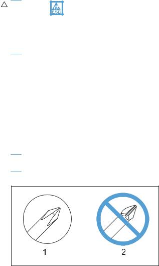
 CAUTION: Always use a Phillips screwdriver (callout 1). Do not use a Pozidriv screwdriver (callout 2) or any motorized screwdriver. These can damage screws or screw threads.
Figure 1-1 Phillips and Pozidriv screwdriver comparison
Service approach
Before performing service
●Remove all paper from the product.
●Turn off the power using the power switch.
●Unplug the power cable and interface cable or cables.
●Place the product on an ESD workstation or mat, or use an ESD strap (if one is available). If an ESD workstation, mat, or strap is not available, ground yourself by touching the sheet-metal chassis before touching an ESD-sensitive part.
●Remove the print cartridge.
ENWW |
Electrostatic discharge 3 |
After performing service
●Plug in the power cable.
●Reinstall the print cartridge.
●Load paper in the product.
Post-service test
Perform the following test to verify that the repair or replacement was successful.
Print-quality test
1.Verify that you have completed the necessary reassembly steps.
2.Make sure that the tray contains clean, unmarked paper.
3.Attach the power cord and interface cable or interface cables, and then turn on the product.
4.Verify that the expected startup sounds occur.
5.Print a configuration page, and then verify that the expected printing sounds occur.
6.Print a demo page, and then verify that the print quality is as expected.
7.Send a print job from the host computer, and then verify that the output meets expectations.
8.Clean the outside of the product with a damp cloth.
Parts removal order
 NOTE: In the following list, parts shown with blue text should be removed only in a clean-room environment. See the Service Manual Addendum for details about removing and replacing these parts.
4 Chapter 1 Removal and replacement |
ENWW |

Figure 1-2 Parts removal order: Scanner and document feeder
Automatic document feeder assembly
ADF tray
ADF top cover
ADF pre-pickup arm and roller
ADF outer cover
ADF cable cover
ADF core
ADF roller post scan pinch
Solar lock
ADF base
Scanner assembly
Control panel
Engine left cover
ADF floating hinge
Scanner bezel (See the Service Manual Addendum)
ADF floating hinge (Also can be removed before the Scanner bezel, tool needed) Scan-drive system
DC servo motor
Scan bar
Scanner base
SSA hinge
Cartridge door arm
ENWW |
Service approach 5 |

Figure 1-3 Parts removal order: Product base
Print cartridge Separation pad Pickup roller Transfer roller Printer side covers
Fax card & formatter
Cartridge door
Front cover
Laser Scanner
Main Motor
Top cover
Duplex door
Duplex frame
Pickup ASSY
Fuser
Pickup solenoid
Engine Controller PCA
Duplex-reverse solenoid
Main fan
Duplexer-connector PCA
6 Chapter 1 Removal and replacement |
ENWW |

Removal and replacement procedures
 NOTE: Many of the figures in the following procedures show the product with the scanner assembly removed. However, removal of the scanner assembly is necessary only when specified in the steps.
Print cartridge
1.Lift the scanner assembly, and then open the cartridge door.
Figure 1-4 Remove the print cartridge (1 of 2)
2.Remove the print cartridge.
Figure 1-5 Remove the print cartridge (2 of 2)
ENWW |
Removal and replacement procedures 7 |

Pickup roller
 CAUTION: Do not touch the sponge portion of the roller. Skin oils can cause paper handling problems.
1.Remove the print cartridge. See Print cartridge on page 7.
2.Release the two tabs between the wheels and the sides of the pick up roller.
Figure 1-6 Remove the pickup roller (1 of 2)
3.Rotate the roller away from the product to remove it.
Figure 1-7 Remove the pickup roller (2 of 2)
8 Chapter 1 Removal and replacement |
ENWW |

Separation pad
 CAUTION: Do not touch the sponge portion of the pad. Skin oils can cause paper handling problems.
1.Place the product on its side to access the separation pad assembly.
 CAUTION: Do not scratch the product covers. Place the product on a cloth or other clean surface to avoid scratches from dirt and debris.
2.Remove two screws (callout 1), and then remove the separation pad assembly (callout 2).
Figure 1-8 Remove the separation pad assembly
2
 1
1
ENWW |
Removal and replacement procedures 9 |
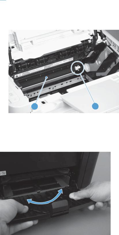
Transfer roller
 CAUTION: Do not touch the sponge portion of the roller. Skin oils can cause print quality problems.
1.Remove the print cartridge. See Print cartridge on page 7.
2.Release two tabs (callout 1), and then remove the transfer roller (callout 2).
Figure 1-9 Remove the transfer roller
2 |
1 |
Covers
Main tray
Open the tray, carefully flex the tray to release the hinges, and then remove the tray.
Figure 1-10 Remove the tray
10 Chapter 1 Removal and replacement |
ENWW |

Output bin extension
Lift the output bin extension (callout 1) up to remove it.
Figure 1-11 Remove the output bin extension
1
ENWW |
Removal and replacement procedures 11 |

Left cover
Before proceeding, remove the following components:
●Main tray. See Main tray on page 10.
●Output bin extension. See Output bin extension on page 11.
Remove the left cover
1.Remove one screw (callout 1).
Figure 1-12 Remove the left cover (1 of 5)
1
2.Open the duplex door (callout 1), and then release two tabs (callout 2).
Figure 1-13 Remove the left cover (2 of 5)
2
1
12 Chapter 1 Removal and replacement |
ENWW |
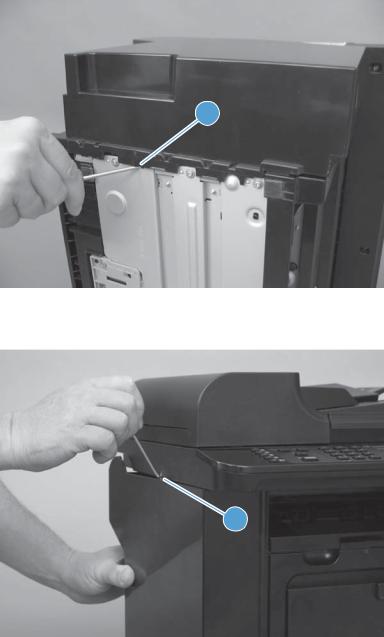
3.Release one tab (callout 1) at the bottom edge of the cover.
Figure 1-14 Remove the left cover (3 of 5)
1
4.Release one tab (callout 1).
Figure 1-15 Remove the left cover (4 of 5)
1
ENWW |
Removal and replacement procedures 13 |
Loading...