


 Loading...
COLOR LASERJET PRO MFP
Troubleshooting Manual
OK
X
M176 |
M177 |

HP Color LaserJet Pro MFP M176, M177
Troubleshooting Manual
Copyright and License
© 2013 Copyright Hewlett-Packard
Development Company, L.P.
Reproduction, adaptation, or translation without prior written permission is prohibited, except as allowed under the copyright laws.
The information contained herein is subject to change without notice.
The only warranties for HP products and services are set forth in the express warranty statements accompanying such products and services. Nothing herein should be construed as constituting an additional warranty. HP shall not be liable for technical or editorial errors or omissions contained herein.
Part number: CZ165-90944
Edition 1, 9/2013
Trademark Credits
Microsoft®, Windows®, Windows® XP, and Windows Vista® are U.S. registered trademarks of Microsoft Corporation.

Conventions used in this guide

 TIP: Tips provide helpful hints or shortcuts.
 NOTE: Notes provide important information to explain a concept or to complete a task.
CAUTION: Cautions indicate procedures that you should follow to avoid losing data or damaging the product.
WARNING! Warnings alert you to specific procedures that you should follow to avoid personal injury, catastrophic loss of data, or extensive damage to the product.
ENWW |
iii |

Table of contents
1 Theory of operation ....................................................................................................................................... |
1 |
Basic operation ...................................................................................................................................................... |
2 |
Major product systems ........................................................................................................................ |
2 |
Sequence of operation ........................................................................................................................ |
3 |
Formatter-control system ..................................................................................................................................... |
4 |
Sleep mode .......................................................................................................................................... |
4 |
Input/output ........................................................................................................................................ |
4 |
CPU ....................................................................................................................................................... |
4 |
Memory ................................................................................................................................................ |
4 |
NAND Flash memory ........................................................................................................................... |
4 |
Firmware .............................................................................................................................................. |
5 |
Memory use ......................................................................................................................................... |
5 |
PJL overview ........................................................................................................................................ |
5 |
LEDM overview .................................................................................................................................... |
5 |
Control panel ....................................................................................................................................... |
5 |
Engine-control system .......................................................................................................................................... |
6 |
DC controller ........................................................................................................................................ |
7 |
Low-voltage power supply ................................................................................................................. |
8 |
High-voltage power supply ................................................................................................................. |
9 |
Fuser control ..................................................................................................................................... |
10 |
Image-formation system .................................................................................................................................... |
11 |
Image-formation process ................................................................................................................. |
12 |
Latent-image formation stage ....................................................................................... |
14 |
Step 1: Primary charging .............................................................................. |
14 |
Step 2: Laser-beam exposure ...................................................................... |
14 |
Developing stage ............................................................................................................ |
15 |
Step 3: Development .................................................................................... |
15 |
Transfer stage ................................................................................................................. |
16 |
Step 4: Primary transfer ............................................................................... |
16 |
Step 5: Secondary transfer .......................................................................... |
16 |
Step 6: Separation from the drum ............................................................... |
17 |
Fusing stage .................................................................................................................... |
17 |
ENWW |
v |
Step 7: Fusing ............................................................................................... |
17 |
Drum cleaning stage ....................................................................................................... |
18 |
Step 8: Drum cleaning .................................................................................. |
18 |
ITB cleaning mechanism ................................................................................................. |
18 |
Pickup, feed, and delivery system ...................................................................................................................... |
20 |
Photo sensors and switches ............................................................................................................. |
21 |
Main-input tray .................................................................................................................................................... |
22 |
Jam detection .................................................................................................................................... |
22 |
Scanner system ................................................................................................................................................... |
23 |
Electrical system ............................................................................................................................... |
23 |
Scanner power-on sequence of events .......................................................................... |
23 |
Copy or scan-to-computer sequence of events ............................................................. |
24 |
Document feeder functions and operation ......................................................................................................... |
25 |
Document feeder operation .............................................................................................................. |
25 |
Document feeder paper path and document feeder sensors .......................................................... |
25 |
Document feeder jam detection ....................................................................................................... |
26 |
Fax functions and operation ............................................................................................................................... |
27 |
Computer and network security features ........................................................................................ |
27 |
PSTN operation ................................................................................................................................. |
27 |
The fax subsystem ............................................................................................................................ |
27 |
Fax card in the fax subsystem .......................................................................................................... |
27 |
Safety isolation ............................................................................................................... |
28 |
Safety-protection circuitry ............................................................................................. |
28 |
Data path ......................................................................................................................... |
28 |
Hook state ....................................................................................................................... |
28 |
Downstream device detection ........................................................................................ |
29 |
Hook switch control ........................................................................................................ |
29 |
Ring detect ...................................................................................................................... |
29 |
Line current control ........................................................................................................ |
29 |
Billing- (metering-) tone filters ...................................................................................... |
29 |
Fax page storage in flash memory ................................................................................................... |
29 |
Stored fax pages ............................................................................................................. |
30 |
Advantages of flash memory storage ............................................................................ |
30 |
2 Solve problems ........................................................................................................................................... |
31 |
Solve problems checklist ..................................................................................................................................... |
32 |
Step 1: Test print functionality ......................................................................................................... |
32 |
Step 2: Test copy functionality ......................................................................................................... |
32 |
Menu map ............................................................................................................................................................ |
33 |
Troubleshooting processes ................................................................................................................................. |
34 |
Determine the problem source ......................................................................................................... |
34 |
vi |
ENWW |
Power subsystem .............................................................................................................................. |
35 |
Power-on checks ............................................................................................................ |
35 |
Tools for troubleshooting ................................................................................................................................... |
36 |
Component diagnostics .................................................................................................................... |
36 |
Engine-test page ............................................................................................................ |
36 |
LCD control-panel tests .................................................................................................. |
36 |
Touchscreen control-panel tests ................................................................................... |
36 |
Diagrams ........................................................................................................................................... |
38 |
Plug/jack locations ......................................................................................................... |
38 |
Locations of connectors ................................................................................................. |
39 |
Locations of major components ..................................................................................... |
41 |
General timing chart ....................................................................................................... |
43 |
General circuit diagram .................................................................................................. |
44 |
Internal print-quality test pages ...................................................................................................... |
45 |
Clean the paper path ....................................................................................................... |
45 |
Print Configuration page ................................................................................................ |
45 |
Print-quality troubleshooting tools ................................................................................................. |
46 |
Repetitive image defects ruler ....................................................................................... |
46 |
Calibrate the product ...................................................................................................... |
47 |
Control panel menus ......................................................................................................................... |
48 |
Touchscreen control panel ............................................................................................. |
48 |
Setup menu .................................................................................................. |
48 |
Fax Menu ....................................................................................................... |
55 |
Copy Menu .................................................................................................... |
57 |
LCD control panel ............................................................................................................ |
59 |
Setup menu .................................................................................................. |
59 |
Interpret control-panel messages .................................................................................................... |
66 |
Control-panel message types ........................................................................................ |
66 |
Control-panel messages ................................................................................................ |
66 |
Clear jams ............................................................................................................................................................ |
73 |
Solve paper feed or jam problems .................................................................................................... |
73 |
The product does not pick up paper ............................................................................... |
73 |
The product picks up multiple sheets of paper .............................................................. |
73 |
Frequent or recurring paper jams .................................................................................. |
73 |
Prevent paper jams ......................................................................................................... |
74 |
Clear jams from the input tray .......................................................................................................... |
75 |
Clear jams in the output bin .............................................................................................................. |
79 |
Clear jams in the document feeder ................................................................................................... |
81 |
Solve paper-handling problems .......................................................................................................................... |
83 |
Solve image-quality problems ............................................................................................................................ |
84 |
General print-quality issues ............................................................................................................. |
84 |
ENWW |
vii |
Color image defects .......................................................................................................................... |
88 |
Copy print-quality problems ............................................................................................................. |
93 |
Scan-quality problems ...................................................................................................................... |
94 |
Prevent scan-quality problems ...................................................................................... |
94 |
Solve scan-quality problems .......................................................................................... |
94 |
Clean the product ................................................................................................................................................ |
95 |
Print a cleaning page ......................................................................................................................... |
95 |
Check the scanner glass for dirt and smudges ................................................................................. |
95 |
Clean the pickup rollers and separation pad in the document feeder ............................................. |
96 |
Solve performance problems .............................................................................................................................. |
97 |
Solve connectivity problems ............................................................................................................................... |
98 |
Solve direct-connect problems ......................................................................................................... |
98 |
Solve wired network problems ......................................................................................................... |
98 |
Poor physical connection ................................................................................................ |
98 |
The computer is using the incorrect IP address for the product ................................... |
98 |
The computer is unable to communicate with the product ........................................... |
99 |
The product is using incorrect link and duplex settings for the network ...................... |
99 |
New software programs might be causing compatibility problems ............................. |
99 |
The computer or workstation might be set up incorrectly ............................................ |
99 |
The product is disabled, or other network settings are incorrect ................................. |
99 |
Solve wireless network problems .................................................................................................... |
99 |
Wireless connectivity checklist .................................................................................... |
100 |
The product does not print after the wireless configuration completes .................... |
100 |
The product does not print, and the computer has a third-party firewall installed ... |
101 |
The wireless connection does not work after moving the wireless router or |
|
product .......................................................................................................................... |
101 |
Cannot connect more computers to the wireless product .......................................... |
101 |
The wireless product loses communication when connected to a VPN ...................... |
101 |
The network does not appear in the wireless networks list ....................................... |
101 |
The wireless network is not functioning ...................................................................... |
101 |
Perform a wireless network diagnostic test ................................................................ |
102 |
Reduce interference on a wireless network ................................................................ |
102 |
Service mode functions ..................................................................................................................................... |
103 |
Secondary service menu ................................................................................................................. |
103 |
Open the secondary service menu ............................................................................... |
103 |
Secondary service menu structure .............................................................................. |
103 |
Product resets ................................................................................................................................. |
105 |
Restore factory settings ............................................................................................... |
105 |
NVRAM initialization ..................................................................................................... |
105 |
Solve fax problems ............................................................................................................................................ |
106 |
Check the hardware setup .............................................................................................................. |
106 |
viii |
ENWW |
Faxes are sending slowly ................................................................................................................ |
107 |
Fax quality is poor ........................................................................................................................... |
108 |
Fax cuts off or prints on two pages ................................................................................................ |
109 |
Product updates ................................................................................................................................................ |
110 |
Appendix A Service and support .................................................................................................................... |
111 |
Hewlett-Packard limited warranty statement ................................................................................................. |
112 |
HP's Premium Protection Warranty: LaserJet toner cartridge limited warranty statement ........................... |
113 |
HP policy on non-HP supplies ........................................................................................................................... |
114 |
HP anticounterfeit Web site .............................................................................................................................. |
115 |
Data stored on the toner cartridge ................................................................................................................... |
116 |
End User License Agreement ............................................................................................................................ |
117 |
OpenSSL ............................................................................................................................................................. |
119 |
Customer self-repair warranty service ............................................................................................................. |
120 |
Customer support .............................................................................................................................................. |
121 |
Appendix B Product specifications ................................................................................................................. |
123 |
Physical specifications ...................................................................................................................................... |
124 |
Power consumption, electrical specifications, and acoustic emissions .......................................................... |
124 |
Environmental specifications ............................................................................................................................ |
124 |
Appendix C Regulatory information ............................................................................................................... |
125 |
FCC regulations .................................................................................................................................................. |
126 |
Environmental product stewardship program ................................................................................................. |
127 |
Protecting the environment ........................................................................................................... |
127 |
Ozone production ............................................................................................................................ |
127 |
Power consumption ........................................................................................................................ |
127 |
Toner consumption ......................................................................................................................... |
127 |
Paper use ......................................................................................................................................... |
127 |
Plastics ............................................................................................................................................ |
127 |
HP LaserJet print supplies .............................................................................................................. |
127 |
Return and recycling instructions ................................................................................................... |
128 |
United States and Puerto Rico ...................................................................................... |
128 |
Multiple returns (more than one cartridge) ............................................... |
128 |
Single returns ............................................................................................. |
128 |
Shipping ...................................................................................................... |
128 |
Non-U.S. returns ........................................................................................................... |
129 |
Paper ............................................................................................................................................... |
129 |
Material restrictions ........................................................................................................................ |
129 |
Disposal of waste equipment by users ........................................................................................... |
130 |
ENWW |
ix |
Electronic hardware recycling ........................................................................................................ |
130 |
Chemical substances ....................................................................................................................... |
130 |
Material Safety Data Sheet (MSDS) ................................................................................................ |
130 |
For more information ...................................................................................................................... |
130 |
Declaration of conformity (M176n model) ....................................................................................................... |
131 |
Declaration of conformity (M177fw model) ..................................................................................................... |
133 |
Safety statements ............................................................................................................................................. |
135 |
Laser safety ..................................................................................................................................... |
135 |
Canadian DOC regulations .............................................................................................................. |
135 |
VCCI statement (Japan) ................................................................................................................... |
135 |
Power cord instructions .................................................................................................................. |
135 |
Power cord statement (Japan) ....................................................................................................... |
135 |
EMC statement (Korea) ................................................................................................................... |
136 |
Laser statement for Finland ........................................................................................................... |
136 |
GS statement (Germany) ................................................................................................................ |
137 |
Substances Table (China) ................................................................................................................ |
137 |
Restriction on Hazardous Substances statement (Turkey) ........................................................... |
137 |
Restriction on Hazardous Substances statement (Ukraine) .......................................................... |
137 |
Eurasian Conformity (Belarus, Kazakhstan, Russia) ...................................................................... |
138 |
Additional statements for telecom (fax) products ........................................................................................... |
139 |
EU Statement for Telecom Operation ............................................................................................ |
139 |
New Zealand Telecom Statements ................................................................................................. |
139 |
Additional FCC statement for telecom products (US) .................................................................... |
139 |
Telephone Consumer Protection Act (US) ...................................................................................... |
140 |
Industry Canada CS-03 requirements ............................................................................................ |
140 |
Vietnam Telecom wired/wireless marking for ICTQC Type approved products ............................ |
141 |
Additional statements for wireless products ................................................................................................... |
142 |
FCC compliance statement—United States ................................................................................... |
142 |
Australia statement ........................................................................................................................ |
142 |
Brazil ANATEL statement ................................................................................................................ |
142 |
Canadian statements ...................................................................................................................... |
142 |
Products with 5 GHz Operation Industry of Canada ....................................................................... |
142 |
Exposure to Radio Frequency Radiation (Canada) ......................................................................... |
142 |
European Union regulatory notice .................................................................................................. |
143 |
Notice for use in France .................................................................................................................. |
143 |
Notice for use in Russia ................................................................................................................... |
143 |
Mexico statement ........................................................................................................................... |
143 |
Taiwan statement ........................................................................................................................... |
144 |
Korean statement ........................................................................................................................... |
144 |
Vietnam Telecom wired/wireless marking for ICTQC Type approved products ............................ |
141 |
x |
ENWW |
Index ........................................................................................................................................................... |
145 |
ENWW |
xi |

List of tables
Table 1-1 Sequence of operation ......................................................................................................................................... |
3 |
|
Table 1-2 Photo sensors and switches .............................................................................................................................. |
21 |
|
Table 1-3 Document feeder sensors .................................................................................................................................. |
25 |
|
Table 2-1 Determine the problem source .......................................................................................................................... |
34 |
|
Table 2-2 |
Plug/jack locations ............................................................................................................................................. |
38 |
Table 2-3 Engine control unit PCA connectors .................................................................................................................. |
39 |
|
Table 2-4 Cross section view .............................................................................................................................................. |
41 |
|
Table 2-5 External covers and doors (base) ...................................................................................................................... |
42 |
|
Table 2-6 Repetitive image defects ruler .......................................................................................................................... |
46 |
|
Table 2-7 HP Web Services menu (touchscreen control panel) ........................................................................................ |
48 |
|
Table 2-8 Reports menu (touchscreen control panel) ....................................................................................................... |
49 |
|
Table 2-9 Self Diagnostics menu (touchscreen control panel) ......................................................................................... |
49 |
|
Table 2-10 Fax Setup menu (touchscreen control panel) ................................................................................................. |
49 |
|
Table 2-11 System Setup menu (touchscreen control panel) ........................................................................................... |
52 |
|
Table 2-12 Service menu (touchscreen control panel) ...................................................................................................... |
54 |
|
Table 2-13 Network Setup menu (touchscreen control panel) ......................................................................................... |
55 |
|
Table 2-14 Fax Menu (touchscreen control panel) ............................................................................................................ |
55 |
|
Table 2-15 Copy Menu (touchscreen control panel) .......................................................................................................... |
57 |
|
Table 2-16 HP Web Services menu (LCD control panel) .................................................................................................... |
48 |
|
Table 2-17 Copy Setup menu (LCD control panel) ............................................................................................................. |
57 |
|
Table 2-18 ID Copy menu (LCD control panel) ................................................................................................................... |
60 |
|
Table 2-19 Reports menu (LCD control panel) .................................................................................................................. |
60 |
|
Table 2-20 Self Diagnostics menu (LCD control panel) ..................................................................................................... |
61 |
|
Table 2-21 System Setup menu (LCD control panel) ......................................................................................................... |
52 |
|
Table 2-22 Service menu (LCD control panel) .................................................................................................................... |
54 |
|
Table 2-23 Network Setup menu (LCD control panel) ....................................................................................................... |
55 |
|
Table 2-24 |
Control-panel messages .................................................................................................................................. |
66 |
Table 2-25 Solve paper-handling problems ...................................................................................................................... |
83 |
|
Table 2-26 General print-quality issues ............................................................................................................................ |
84 |
|
Table 2-27 Color image defects ......................................................................................................................................... |
88 |
|
Table 2-28 Copy print-quality problems ............................................................................................................................ |
93 |
|
Table 2-29 |
Scan-quality problems ..................................................................................................................................... |
94 |
ENWW |
xiii |
Table 2-30 Solve performance problems .......................................................................................................................... |
97 |
|
Table 2-31 Secondary service menu ................................................................................................................................ |
103 |
|
Table B-1 |
Physical specifications ..................................................................................................................................... |
124 |
Table B-2 |
Product dimensions with document feeder opened ....................................................................................... |
124 |
Table B-3 |
Operating-environment specifications ........................................................................................................... |
124 |
xiv |
ENWW |

List of figures
Figure 1-1 |
Product systems ................................................................................................................................................. |
2 |
Figure 1-2 Engine control system components ................................................................................................................... |
6 |
|
Figure 1-3 DC controller circuit diagram .............................................................................................................................. |
7 |
|
Figure 1-4 Low-voltage power supply ................................................................................................................................. |
8 |
|
Figure 1-5 High-voltage power supply ................................................................................................................................ |
9 |
|
Figure 1-6 |
Image-formation system .................................................................................................................................. |
12 |
Figure 1-7 |
Image-formation process ................................................................................................................................. |
13 |
Figure 1-8 |
Primary charging ............................................................................................................................................... |
14 |
Figure 1-9 |
Laser-beam exposure ....................................................................................................................................... |
14 |
Figure 1-10 |
Development .................................................................................................................................................. |
15 |
Figure 1-11 |
Primary transfer ............................................................................................................................................. |
16 |
Figure 1-12 |
Secondary transfer ......................................................................................................................................... |
16 |
Figure 1-13 Separation from the drum .............................................................................................................................. |
17 |
|
Figure 1-14 |
Fusing .............................................................................................................................................................. |
17 |
Figure 1-15 |
Drum cleaning ................................................................................................................................................. |
18 |
Figure 1-16 ITB cleaning mechanism ................................................................................................................................. |
18 |
|
Figure 1-17 Pickup, feed, and delivery system block diagram ......................................................................................... |
20 |
|
Figure 1-18 Photo sensors and switches ........................................................................................................................... |
21 |
|
Figure 1-19 Document feeder paper path and document feeder sensors ........................................................................ |
25 |
|
Figure 2-1 |
Plug/jack locations ........................................................................................................................................... |
38 |
Figure 2-2 Locations of connectors ................................................................................................................................... |
39 |
|
Figure 2-3 Cross section view ............................................................................................................................................. |
41 |
|
Figure 2-4 External covers and doors (base) ..................................................................................................................... |
42 |
|
Figure 2-5 General timing diagram .................................................................................................................................... |
43 |
|
Figure 2-6 General circuit diagram ..................................................................................................................................... |
44 |
|
ENWW |
xv |

1 Theory of operation
This chapter presents an overview of the major components of the product, and it includes a detailed discussion of the image-formation system.
●Basic operation
●Formatter-control system
●Engine-control system
●Image-formation system
●Pickup, feed, and delivery system
●Main-input tray
●Scanner system
●Document feeder functions and operation
●Fax functions and operation
ENWW |
1 |
Basic operation
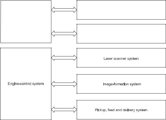
Major product systems
The product includes the following systems:
●Document feeder
●Document scanner
●Engine control system
●Laser/scanner system
●Image-formation system
●Pickup-and-feed system
Figure 1-1 Product systems
Document feeder
Formatter
Document scanner
2 Chapter 1 Theory of operation |
ENWW |

Sequence of operation
Table 1-1 Sequence of operation
Period |
Duration |
Purpose |
Remarks |
WAIT |
From the time the power is |
|
turned on or the door is closed |
|
until the drum-phase |
|
adjustment is complete |
Clears the potential from the drum surface, adjusts the drum phase, and cleans the intermediate transfer belt (ITB)
Detects the toner level, cartridge presence, and environment; completes any required calibration (color registration control and image stability)
STBY (Standby period) |
From end of the WAIT or LSTR |
Maintains the product in |
The product enters STBY mode |
|
period until either the print |
readiness for a print command |
when the formatter sends a |
|
command is received from the |
|
sleep command; the product |
|
formatter or the power is |
|
performs color registration and |
|
turned off |
|
the image stability control |
|
|
|
when the formatter sends |
|
|
|
those commands |
|
|
|
|
INTR (Initial rotation) |
From the time the print |
Prepares the photosensitive |
|
|
command is received until the |
drum for printing |
|
|
paper is picked up |
|
|
|
|
|
|
From the end of INTR period |
Forms the images on the |
Performs image stabilization at |
|
|
until the fuser paper sensor |
photosensitive drum and |
a specified print interval or at |
|
detects the trailing edge of |
transfers the toner image to |
specified times |
|
paper |
the paper |
|
|
|
|
|
LSTR (Last rotation) |
From the end of the PRINT |
Moves the printed sheet out of |
The product enters the INTR |
|
period until the motor stops |
the product |
period as soon as the formatter |
|
rotating |
|
sends another print command |
|
|
|
|
ENWW |
Basic operation 3 |
Formatter-control system
The formatter is responsible for the following procedures:
●Controlling Sleep mode
●Receiving and processing print data from the various product interfaces
●Monitoring control-panel functions and relaying product-status information (through the control panel and the network or bidirectional interface)
●Developing and coordinating data placement and timing with the DC controller PCA
●Storing font information
●Communicating with the host computer through the network or the bidirectional interface
The formatter receives a print job from the network or bidirectional interface and separates it into image information and instructions that control the printing process. The DC controller PCA synchronizes the imageformation system with the paper-input and -output systems, and then signals the formatter to send the print-image data.
Sleep mode
After a user-specified time, the Sleep mode feature automatically conserves electricity by substantially reducing power consumption when the product is not printing. After a user-specified time, the product automatically reduces its power consumption (Sleep mode). The product returns to the ready state when a button is pressed, a print job is received, or a door is opened. When the product is in Sleep mode, all of the control-panel LEDs and the power button backlight LED are off.
Input/output
The product receives print data primarily from the following:
●Hi-Speed USB 2.0 port
●10/100/1000 Ethernet LAN connection
●802.11b/g/n wireless networking
CPU
The formatter incorporates a 600 MHz Arm processor.
Memory
The random access memory (RAM) on the formatter PCA contains the page, I/O buffers, and the font storage area. RAM stores printing and font information received from the host system, and can also serve to temporarily store a full page of print-image data before the data is sent to the print engine.
NAND Flash memory
The Smart Install CD image (ISO) is stored in the NAND Flash non-volatile memory. This memory can be reprogrammed through the firmware.
4 Chapter 1 Theory of operation |
ENWW |
Firmware
The product has 128 MB of DDR-2 SDRAM, which is used for run-time firmware imaging and print, scan and copy job information during printing.
Memory use
The product has a 16 KB EEPROM and 16 MB of SPI NOR Flash Memory, which is used for product configuration information and print driver firmware.
PJL overview
The print job language (PJL) is an integral part of configuration, in addition to the standard print command language (PCL). With standard cabling, the product can use PJL to perform a variety of functions such as these:
●Two-way communication with the host computer through a network connection or a USB connection. The product can inform the host about such things as the control-panel settings, and the control-panel settings can be changed from the host.
●Dynamic I/O switching. The product uses this switching to be configured with a host on each I/O. The product can receive data from more than one I/O simultaneously, until the I/O buffer is full. This can occur even when the product is offline.
●Context-sensitive switching. The product can automatically recognize the personality (PS or PCL) of each job and configure itself to serve that personality.
●Isolation of print environment settings from one print job to the next. For example, if a print job is sent to the product in landscape mode, the subsequent print jobs print in landscape mode only if they are formatted for landscape printing.
LEDM overview
The low-end data model (LEDM) provides one consistent data representation method and defines the dynamic and capabilities tickets shared between clients and devices, as well as the access protocol, event, security, and discovery methods.
Control panel
The formatter sends and receives product status and command data to and from the control-panel PCA.
ENWW |
Formatter-control system 5 |

Engine-control system
The engine control system coordinates all product functions and drives the other three systems.
The engine control system contains the DC controller, low-voltage power supply PCA, high-voltage power supply PCA, and fuser control PCA.
Figure 1-2 Engine control system components
6 Chapter 1 Theory of operation |
ENWW |
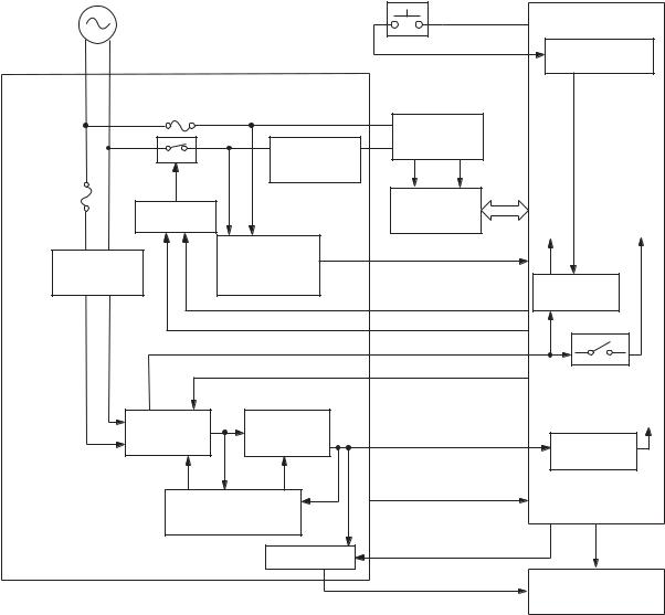
DC controller
The DC controller controls the operational sequences of the product.
Figure 1-3 DC controller circuit diagram
Engine controller
Connector PCA
Low-voltage |
Motor |
|
power supply |
||
|
Fuser
Solenoid
ITB ass’y
Photointerruptor
T2 roller |
High-voltage |
DC controller |
|
|
|||
power supply |
Sensor |
||
|
|||
Cartridge |
|
Switch |
|
|
|
Control panel |
|
|
Formatter |
|
|
||
|
|
|
|
Laser scanner ass’y
LED
ENWW |
Engine-control system 7 |
Low-voltage power supply
The low-voltage power supply converts AC power from the wall receptacle into DC voltage power.
Figure 1-4 Low-voltage power supply
|
|
|
DC controller |
AC power |
Power switch |
+24V |
|
SW7001 |
|
|
|
|
Low-voltage power supply |
PWSW |
Remote switch |
|
|
control circuit |
|
Fuse |
|
|
|
|
|
FU101 |
|
|
|
|
|
|
|
Connector |
|
|
|
|
Fuser control |
PCA |
|
|
|
|
|
|
|
|
|
Relay |
circuit |
|
|
|
Fuse |
|
|
|
|
|
RL401 |
|
|
|
|
|
FU102 |
Relay control |
|
Fuser |
|
|
|
|
|
|
||
|
circuit |
|
|
+24V |
+24B |
|
|
|
|
||
|
|
Frequency |
FREQSNS |
|
|
Rectifying |
detection circuit |
|
|
||
|
|
|
|||
|
circuit |
200V model only |
|
Switching |
|
|
|
RLD+ |
|
||
|
|
|
circuit |
|
|
|
|
|
RLD- |
|
|
|
|
|
+24R |
|
|
|
|
|
PWSV |
Interlock switch |
|
|
|
|
|
||
|
|
|
|
SW501 |
|
|
+24V |
+3.3V |
|
|
+3.3T |
|
generation |
generation |
+3.3R |
Switching |
|
|
circuit |
circuit |
|
||
|
|
|
|||
|
|
|
|
circuit |
|
|
|
|
LVT100V |
|
|
|
Protection circuit |
|
|
|
|
|
|
Switch |
/REM3V_V |
+24V |
|
|
|
|
|
|
|
|
|
|
+3.3V |
Formatter |
|
|
|
|
|
|
|
8 Chapter 1 Theory of operation |
ENWW |

High-voltage power supply
Figure 1-5 High-voltage power supply
 brush
brush
ENWW |
Engine-control system 9 |
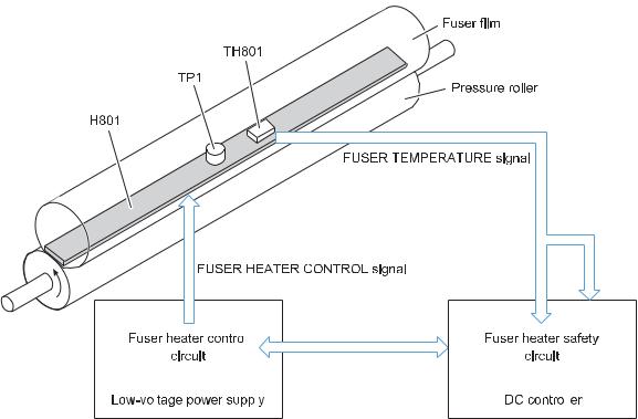
Fuser control
|
|
|
|
|
|
|
|
|
|
|
|
|
|
|
|
|
|
|
|
|
|
|
|
|
|
|
|
|
|
|
|
|
|
|
|
|
|
|
|
10 Chapter 1 Theory of operation |
|
|
|
ENWW |
|||
Image-formation system
The DC controller controls the image-formation system according to commands from the formatter.
The DC controller controls the internal components of the image scanner system to form the toner image on the photosensitive drum surface. The toner image is transferred to the paper and fused.
The following are the main components of the image-formation system.
●Imaging drum
●Laser scanner assembly
●Carousel
●Four toner cartridges
●ITB
●ITB drive roller
●T1 pad
●ITB cleaning brush
●ITB cleaning roller
●T2 roller
●Fuser film assembly
●Pressure roller
●High-voltage power supply
ENWW |
Image-formation system 11 |
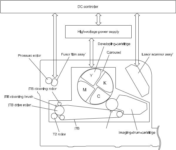
The following image shows the components of the image-formation system.
Figure 1-6 Image-formation system
 brush
brush
Image-formation process
The DC controller rotates the following motors to drive each component.
Main motor
●ITB drive roller
●ITB (follows the ITB drive roller)
●T2 roller (follows the ITB)
●Imaging drum
●Primary charging roller (part of the imaging drum)
●Developing roller (part of the toner cartridge)
12 Chapter 1 Theory of operation |
ENWW |
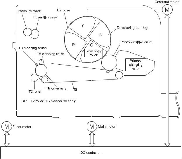
Carousel motor
●Carousel
●Engagement/Disengagement of the developing-cartridge (follows the carousel)
Fuser motor
●Pressure roller
●Fuser film (follows the pressure roller)
●Engagement/Disengagement of the T2 roller, ITB cleaning roller and ITB cleaning brush
Figure 1-7 Image-formation process
|
|
|
|
|
|
|
|
|
|
|
|
|
|
|
|
|
|
|
|
|
|
|
|
|
|
|
|
|
|
|
|
|
|
|
|
|
|
|
|
|
|
|
|
|
|
|
|
|
|
|
|
|
|
|
|
|
|
|
|
|
|
|
|
|
|
|
|
|
|
|
|
|
|
|
|
|
|
|
|
|
|
|
|
|
|
|
|
|
|
|
|
|
|
|
|
|
|
|
|
|
|
|
|
|
|
|
|
|
|
|
|
|
|
|
|
|
|
|
|
|
|
|
|
|
|
|
|
|
|
|
|
|
|
|
|
|
|
|
|
|
|
|
|
|
|
|
|
|
|
|
|
|
|
|
|
|
|
|
|
|
|
|
|
|
|
|
|
|
|
|
|
|
|
|
|
|
|
|
|
|
|
|
|
|
|
|
|
|
|
|
|
|
|
|
|
|
|
|
|
|
|
|
|
|
|
|
|
|
|
|
|
|
|
|
|
|
|
|
|
|
|
|
|
|
|
|
|
|
|
|
|
|
|
|
|
|
|
|
|
|
|
|
|
|
|
|
|
|
|
|
|
|
|
|
|
|
|
|
|
|
|
|
|
|
|
|
|
|
|
|
|
|
|
|
|
|
|
|
|
|
|
|
|
|
|
|
|
|
|
|
|
|
|
|
|
|
|
|
|
|
|
|
|
|
|
|
|
|
|
|
|
|
|
|
|
|
|
|
|
|
|
|
|
|
|
|
|
|
|
|
|
|
|
|
|
|
|
|
|
|
|
|
|
|
|
|
|
|
|
|
|
|
|
|
|
|
|
|
|
|
|
|
|
|
|
|
|
|
|
|
|
|
|
|
|
|
|
|
|
|
|
|
|
|
|
|
|
|
|
|
|
|
|
|
|
|
|
|
|
|
|
|
|
|
|
|
|
|
|
|
|
|
|
|
|
|
|
|
|
|
|
|
|
|
|
|
|
|
|
|
|
|
|
|
|
|
|
|
|
|
|
|
|
|
|
|
|
|
|
|
|
|
|
|
|
|
|
|
|
|
|
|
|
|
|
|
|
|
|
|
|
|
|
|
|
|
|
|
|
|
|
|
|
|
|
|
|
|
|
|
|
|
|
|
|
|
|
|
|
|
|
|
|
|
|
|
|
|
|
|
|
|
|
|
|
|
|
|
|
|
|
|
|
|
|
|
|
|
|
|
|
|
|
|
|
|
|
|
|
|
|
|
|
|
|
|
|
|
|
|
|
|
|
|
|
|
|
|
|
|
|
|
|
|
|
|
|
|
|
|
|
|
|
|
|
|
|
|
|
|
|
|
|
|
|
|
|
|
|
|
|
|
|
|
|
|
|
|
|
|
|
|
|
|
|
|
|
|
|
|
|
|
|
|
|
|
|
|
|
|
|
|
|
|
|
|
|
|
|
|
|
|
|
|
|
|
|
|
|
|
|
|
|
|
|
|
|
|
|
|
|
|
|
|
|
|
|
|
|
|
|
|
|
|
|
|
|
|
|
|
|
|
|
|
|
|
|
|
|
|
|
|
|
|
|
|
|
|
|
|
|
|
|
|
|
|
|
|
|
|
|
|
|
|
|
|
|
|
|
|
|
|
|
|
|
|
|
|
|
|
|
|
|
|
|
|
|
|
|
|
|
|
|
|
|
|
|
|
|
|
|
|
|
|
|
|
|
|
|
|
|
|
|
|
|
|
|
|
|
|
|
|
|
|
|
|
|
|
|
|
|
|
|
|
|
|
|
|
|
|
|
|
|
|
|
|
|
|
|
|
|
|
|
|
|
|
|
|
|
|
|
|
|
|
|
|
|
|
|
|
|
|
|
|
|
|
|
|
|
|
|
|
|
|
|
|
|
|
|
|
|
|
|
|
|
|
|
|
|
|
|
|
|
|
|
|
|
|
|
|
|
|
|
|
|
|
|
|
|
|
|
|
|
|
|
|
|
|
|
|
|
|
|
|
|
|
|
|
|
|
|
|
|
|
|
|
|
|
|
|
|
|
|
|
|
|
|
|
|
|
|
|
|
|
|
|
|
|
|
|
|
|
|
|
|
|
|
|
|
|
|
|
|
|
|
|
|
|
|
|
|
|
|
|
|
|
|
|
|
|
|
|
|
|
|
|
|
|
|
|
|
|
|
|
|
|
|
|
|
|
|
|
|
|
|
|
|
|
|
|
|
|
|
|
|
|
|
|
|
|
|
|
|
|
|
|
|
|
|
|
|
|
|
|
|
|
|
|
|
|
|
|
|
|
|
|
|
|
|
|
|
|
|
|
|
|
|
|
|
|
|
|
|
|
|
|
|
|
|
|
|
|
|
|
|
|
|
|
|
|
|
|
|
|
|
|
|
|
|
|
|
|
|
|
|
ENWW |
Image-formation system 13 |
|||||||||||||||||||||||||||||||

Latent-image formation stage
During the two steps that comprise this stage, a latent image is formed by applying a negative charge to the photosensitive drum. This image is not visible on the drum.
Step 1: Primary charging
A high-voltage DC bias is applied to the primary charging roller, which is made of conductive rubber and is in contact with the drum surface. As the roller moves across the drum, it applies the negative charge to that surface.
Figure 1-8 Primary charging
Step 2: Laser-beam exposure
The laser beam scans the photosensitive drum to neutralize the negative charge on portions of the drum surface. An electrostatic latent image is formed where the negative charge was neutralized.
Figure 1-9 Laser-beam exposure
14 Chapter 1 Theory of operation |
ENWW |
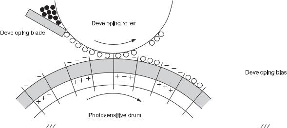
Developing stage
The developing cylinder comes in contact with the photosensitive drum and deposits toner on the electrostatic latent image.
Step 3: Development
The toner acquires a negative charge as a result of the friction from the developing cylinder rotating against the developing blade. When the negatively charged toner comes in contact with the drum, it adheres to the electrostatic latent image. When the toner is on the drum, the image becomes visible.
Figure 1-10 Development
|
|
|
|
|
|
|
|
|
|
|
|
|
|
|
|
|
|
|
|
|
|
|
|
|
|
|
|
|
|
|
|
|
|
|
|
|
|
|
|
|
|
|
|
|
|
|
|
|
|
|
|
|
|
|
|
|
|
|
|
|
|
|
|
|
|
|
|
|
|
|
|
|
|
|
|
|
|
|
|
|
|
|
|
|
|
|
|
|
|
|
|
|
|
|
|
|
|
|
|
|
|
|
|
|
|
|
|
|
|
|
|
|
|
|
|
|
|
|
|
|
|
|
|
|
|
|
|
|
|
|
|
|
|
|
|
|
|
|
|
|
|
|
|
|
|
|
|
|
|
|
|
|
|
|
|
|
|
|
|
|
|
|
|
|
|
|
|
|
|
|
|
|
|
|
|
|
|
|
|
|
|
|
|
|
|
|
|
|
|
|
|
|
|
|
|
|
|
|
|
|
|
|
|
|
|
|
|
|
|
|
|
|
|
|
|
|
|
|
|
|
|
|
|
|
|
|
|
|
|
|
|
|
|
|
|
|
|
|
|
|
|
|
|
|
|
|
|
|
|
|
|
|
|
|
|
|
|
|
|
|
|
|
|
|
|
|
|
|
|
|
|
|
|
|
|
|
|
|
|
|
|
|
|
|
|
|
|
|
|
|
|
|
|
|
|
|
|
|
|
|
|
|
|
|
|
|
|
|
|
|
|
|
|
|
|
|
|
|
|
|
|
|
|
|
|
|
|
|
|
|
|
|
|
|
|
|
|
|
|
|
|
|
|
|
|
|
|
|
|
|
|
|
|
|
|
|
|
|
|
|
|
|
|
|
|
|
|
|
|
|
|
|
|
|
|
|
|
|
|
|
|
|
|
|
|
|
|
|
|
|
|
|
|
|
|
|
|
|
|
|
|
|
|
|
|
|
|
|
|
|
|
|
|
|
|
|
|
|
|
|
|
|
|
|
|
|
|
|
|
|
|
|
|
|
|
|
|
|
|
|
|
|
|
|
|
|
|
|
|
|
|
|
|
|
|
|
|
|
|
|
|
|
|
|
|
|
|
|
|
|
|
|
|
|
|
|
|
|
|
|
|
|
|
|
|
|
|
|
|
|
|
|
|
|
|
|
|
|
|
|
|
|
|
|
|
|
|
|
|
|
|
|
|
|
|
|
|
|
|
|
|
|
|
|
|
|
|
|
|
|
|
|
|
|
|
|
|
|
|
|
|
|
|
|
|
|
|
|
|
|
|
|
|
|
|
|
|
|
|
|
|
|
|
|
|
|
|
|
|
|
|
|
|
|
|
|
|
|
|
|
|
|
|
|
|
|
|
|
|
|
|
|
|
|
|
|
|
|
|
|
|
|
|
|
|
|
|
|
|
|
|
|
|
|
|
|
|
|
|
|
|
|
|
|
|
|
|
|
|
|
|
|
|
|
|
|
|
|
|
|
|
|
|
|
|
|
|
|
|
|
|
|
|
|
|
|
|
|
|
|
|
|
|
|
|
|
|
|
|
|
|
|
|
|
|
|
|
|
|
|
|
|
|
|
|
|
|
|
|
|
|
|
|
|
|
|
|
|
|
|
|
|
|
|
|
|
|
|
|
|
|
|
|
|
|
|
|
|
|
|
|
|
|
|
|
|
|
|
|
|
|
|
|
|
|
|
|
|
|
|
|
|
|
|
|
|
|
|
|
|
|
|
|
|
|
|
|
|
|
|
|
|
|
|
|
|
|
|
|
|
|
|
|
|
|
|
|
|
|
|
|
|
|
|
|
|
|
|
|
|
|
|
|
|
|
|
|
|
|
|
|
|
|
|
|
|
|
|
|
|
|
|
|
|
|
|
|
|
|
|
|
|
|
|
|
|
|
|
|
|
|
|
|
|
|
|
|
|
|
|
|
|
|
|
|
|
|
|
|
|
|
|
|
|
|
|
|
|
|
|
|
|
|
|
|
|
|
|
|
|
|
|
|
|
|
|
|
|
|
|
|
|
|
|
|
|
|
|
|
|
|
|
|
|
|
|
|
|
|
|
|
|
|
|
|
|
|
|
|
|
|
|
|
|
|
|
|
|
|
|
|
|
|
|
|
|
|
|
|
|
|
|
|
|
|
|
|
|
|
|
|
|
|
|
|
|
|
|
|
|
|
|
|
|
|
|
|
|
|
|
|
|
|
|
|
|
|
|
|
|
|
|
|
|
|
|
|
|
|
|
|
|
|
|
|
|
|
|
|
|
|
|
|
|
|
|
|
|
|
|
|
|
|
|
|
|
|
|
|
|
|
|
|
|
|
|
|
|
|
|
|
|
|
|
|
|
|
|
|
|
|
|
|
|
|
|
|
|
|
|
|
|
|
|
|
|
|
|
|
|
|
|
|
|
|
|
|
|
|
|
|
|
|
|
|
|
|
|
|
|
|
|
|
|
|
|
|
|
|
|
|
|
|
|
|
|
|
|
|
|
|
|
|
|
|
|
|
|
|
ENWW |
|
|
|
|
|
Image-formation system 15 |
|||||||||||||||||||||||||||||||||||||||||||
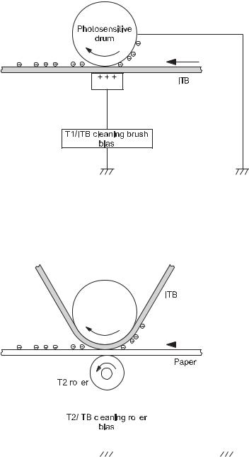
Transfer stage
Step 4: Primary transfer
The toner image on the photosensitive drum is transferred to the ITB. The DC positive bias is applied to the primary transfer pad. The negatively charged toner transfers to the ITB from the drum surface.
Figure 1-11 Primary transfer
 brush
brush
Step 5: Secondary transfer
The toner image on the ITB is transferred to the paper. The DC positive bias is applied to the secondary transfer roller. As the paper passes between the secondary transfer roller and the ITB, the toner image is transferred to the paper.
Figure 1-12 Secondary transfer
|
|
|
|
|
|
|
|
|
|
|
|
|
|
|
|
|
|
|
|
|
|
|
|
|
|
|
|
|
|
|
|
|
|
|
|
|
|
|
|
|
|
|
|
|
|
|
|
|
|
|
|
|
|
|
|
|
|
|
|
|
|
|
|
|
|
|
|
|
|
|
|
|
|
|
|
|
|
|
|
|
|
|
|
|
|
|
|
|
|
|
|
|
|
|
|
|
|
|
|
|
|
|
|
|
|
|
|
|
|
|
|
|
|
|
|
|
|
|
|
|
|
|
|
|
|
|
|
|
|
|
|
|
|
|
|
|
|
|
|
|
|
|
|
|
|
|
|
|
|
|
|
|
|
|
|
|
|
|
|
|
|
|
|
|
|
|
|
|
|
|
|
|
|
|
|
|
|
|
|
|
|
|
|
|
|
|
|
|
|
|
|
|
|
|
|
|
|
|
|
|
|
|
|
|
|
|
|
|
|
|
|
|
|
|
|
|
|
|
|
|
|
|
|
|
|
|
|
|
|
|
|
|
|
|
|
|
|
|
|
|
|
|
|
|
|
|
|
|
|
|
|
|
|
|
|
|
|
|
|
|
|
|
|
|
|
|
|
|
|
|
|
|
|
|
|
|
|
|
|
|
|
|
|
|
|
|
|
|
|
|
|
|
|
|
|
|
|
|
|
|
|
|
|
|
|
|
|
|
|
|
|
|
|
|
|
|
|
|
|
|
|
|
|
|
|
|
|
|
|
|
|
|
|
|
|
|
|
|
|
|
|
|
|
|
|
|
|
|
|
|
|
|
|
|
|
|
|
|
|
|
|
|
|
|
|
|
|
|
|
|
|
|
|
|
|
|
|
|
|
|
|
|
|
|
|
|
16 Chapter 1 Theory of operation |
|
|
|
|
|
ENWW |
||||||||||||||||||||||||||||||||||||
Loading...