


 Loading...
Maintenance and Service
Guide
HP Docking Station
HP Advanced Docking Station
Document Part Number: 381882-003
May 2007
This guide is a troubleshooting reference used for maintaining and servicing the HP Docking Station and the HP Advanced Docking Station. It provides comprehensive information on identifying docking station features, components, and spare parts; troubleshooting problems; and performing disassembly procedures.
© Copyright 2005–2007 Hewlett-Packard Development Company, L.P.
The information contained herein is subject to change without notice. The only warranties for HP products and services are set forth in the express warranty statements accompanying such products and services. Nothing herein should be construed as constituting an additional warranty. HP shall not be liable for technical or editorial errors or omissions contained herein.
Maintenance and Service Guide
HP Docking Station
HP Advanced Docking Station
Third Edition: May 2007
First Edition: January 2005
Document Part Number: 381882-003

Contents
1 Product Description
1.1 Features . . . . . . . . . . . . . . . . . . . . . . . . . . . . . . . . . . . 1–4
1.2 External Components . . . . . . . . . . . . . . . . . . . . . . . . 1–6
1.3 Design Overview. . . . . . . . . . . . . . . . . . . . . . . . . . . 1–18
2 Troubleshooting
2.1 Troubleshooting Checklist . . . . . . . . . . . . . . . . . . . . 2–2
2.2 Problems and Solutions. . . . . . . . . . . . . . . . . . . . . . . 2–2
3 Illustrated Parts Catalog
3.1 Serial Number Location . . . . . . . . . . . . . . . . . . . . . . 3–1
3.2 Major Components . . . . . . . . . . . . . . . . . . . . . . . . . . 3–2
3.3 Miscellaneous Spares Kit . . . . . . . . . . . . . . . . . . . . . 3–4
3.4 Sequential Part Number Listing . . . . . . . . . . . . . . . . 3–6
4 Removal and Replacement Preliminaries
4.1 Tools Required . . . . . . . . . . . . . . . . . . . . . . . . . . . . . 4–1
4.2 Service Considerations . . . . . . . . . . . . . . . . . . . . . . . 4–1
Plastic Parts . . . . . . . . . . . . . . . . . . . . . . . . . . . . . . . . 4–2
Cables and Connectors . . . . . . . . . . . . . . . . . . . . . . . 4–2
4.3 Preventing Electrostatic Damage . . . . . . . . . . . . . . . 4–2
4.4 Packaging and Transporting Precautions . . . . . . . . . 4–3
4.5 Workstation Precautions . . . . . . . . . . . . . . . . . . . . . . 4–4
4.6 Grounding Equipment and Methods . . . . . . . . . . . . . 4–4
Maintenance and Service Guide |
iii |

Contents
5 Removal and Replacement Procedures
5.1 Serial Number . . . . . . . . . . . . . . . . . . . . . . . . . . . . . . 5–1 5.2 Preparing the Docking Station for Disassembly . . . . 5–2 5.3 Installing the Cable Lock . . . . . . . . . . . . . . . . . . . . . 5–4
6 Specifications
AScrew Listing
BConnector Pin Assignments
CPower Cord Set Requirements Index
iv |
Maintenance and Service Guide |

1
Product Description
The HP Docking Station and HP Advanced Docking Station provide desktop convenience with full port replication capability in a space-saving design. The easy docking system provides port replication and cable management in one product. The advanced docking station also provides a MultiBay II slot and an ExpressCard slot.
Maintenance and Service Guide |
1–1 |

Product Description
HP Advanced Docking Station and HP Smart Adapter
HP Docking Station and HP Smart Adapter
1–2 |
Maintenance and Service Guide |

Product Description
The HP Docking Station and HP Advanced Docking Station are compatible with the following computer models:
■HP Compaq nc2400 Notebook PC
■HP Compaq nc4200 and nc4400 Notebook PCs
■HP Compaq tc4200 and tc4400 Tablet PCs
■HP Compaq nc6110, nc6120, and nc6140 Notebook PCs
■HP Compaq nx6110 and nx6120 Notebook PCs
■HP Compaq nc/nx6115 and nc/nx6125 Notebook PCs
■HP Compaq nc6220 and nc6230 Notebook PCs
■HP Compaq nx6320, nc6320, and nx6310 Notebook PCs
■HP Compaq nx6325 and HP Compaq nx6315 Notebook PCs
■HP Compaq nc6400 Notebook PC
■HP Compaq 6510b and 6515b Notebook PCs
■HP Compaq 6710s, 6710b, 6715s, and 6715b Notebook PCs
■HP Compaq nx7400 Notebook PC
■HP Compaq nc8200, nw8200, and nx8200 Notebook PCs
■HP Compaq nw8440, nc8430, and nx8420 Notebook PCs
■HP Compaq 8510w and 8510p Notebook PCs
■HP Compaq 8710w and 8710p Notebook PCs
■HP Compaq nw9440 and nx9420 Notebook PCs
Maintenance and Service Guide |
1–3 |

Product Description
1.1Features
■Integrated cable lock slot
■Security slot (for standard cable lock)
■HP Smart Adapter external AC adapter (charges docked PC)
■Lights (power, docking)
■Integrated MultiBay II (advanced docking station only)
■MultiBay II activity light (advanced docking station only)
■ExpressCard slot (advanced docking station only)
■Dual-link DVI support for following computer models:
HP Compaq 8510p and 8510w Notebook PC
HP Compaq 8710p and 8710w Notebook PC
1–4 |
Maintenance and Service Guide |

Product Description
Connectors:
Monitor stand port
External monitor port
Serial port
Parallel port
Keyboard connector
Mouse connector
Audio-out (headphone) jack
Audio-in (microphone) jack
Digital video (DVI) port
Composite video jack
RJ-45/Ethernet (network) jack
RJ-11 (modem) jack
Universal Serial Bus (USB) 2.0 ports
Docking station—3 USB 2.0 ports
Advanced docking station—5 USB 2.0 ports
Powered USB port
S-Video-out jack
Power connector
Maintenance and Service Guide |
1–5 |
Product Description
1.2 External Components
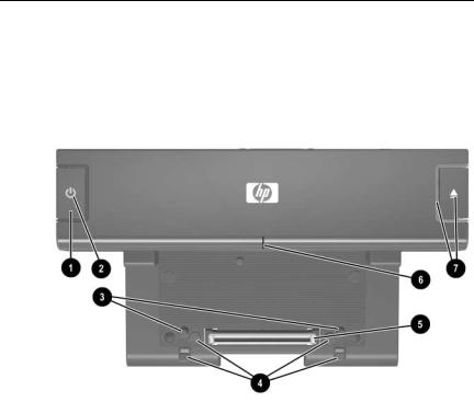
The external components on the top of the docking station are shown in the following illustration and described in Table 1-1.
Top Components, Docking Station
1–6 |
Maintenance and Service Guide |
Product Description
Table 1-1
Top Components, Docking Station
Item |
Component |
Description |
|
|
|
1 |
Power button |
Turns on power to the computer. |
|
|
|
2 |
Power light |
Indicates the state of the computer and is |
|
|
turned on when the computer is turned on. |
|
|
|
3 |
Docking posts (2) |
Align and secure the computer for proper |
|
|
connection to the docking station. |
|
|
|
4 |
Computer eject |
Disconnect the computer from the docking |
|
mechanisms (4) |
station when you press the eject button. |
|
|
|
5 |
Docking connector |
Connects the computer to the |
|
|
docking station. |
|
|
|
6 |
Visual alignment |
Helps you correctly align the computer |
|
indicator |
when connecting it to the docking station. |
|
|
|
7 |
Computer eject button |
Ejects the computer from the docking |
|
and docking light |
station. The docking light is turned on when |
|
|
the computer is properly aligned. |
|
|
|
Maintenance and Service Guide |
1–7 |

Product Description
The external components on the top of the advanced docking station are shown in the following illustration and described in Table 1-2.
Top Components, Advanced Docking Station
1–8 |
Maintenance and Service Guide |

Product Description
Table 1-2
Top Components, Advanced Docking Station
Item |
Component |
Description |
|
|
|
1 |
Power button |
Turns on power to the computer. |
|
|
|
2 |
Power light |
Indicates the state of the computer and is |
|
|
turned on when the computer is turned on. |
|
|
|
3 |
Docking posts (2) |
Align and secure the computer for |
|
|
proper connection to the docking station. |
|
|
|
4 |
Computer eject |
Disconnect the computer from the docking |
|
mechanisms (4) |
station when you press the eject button. |
|
|
|
5 |
Docking connector |
Connects the computer to the docking |
|
|
station. |
|
|
|
6 |
Visual alignment |
Helps you correctly align the computer |
|
indicator |
when connecting it to the docking station. |
|
|
|
7 |
Computer eject button |
Ejects the computer from the docking |
|
and docking light |
station. The docking light is turned on |
|
|
when the computer is properly aligned. |
|
|
|
Maintenance and Service Guide |
1–9 |
Product Description
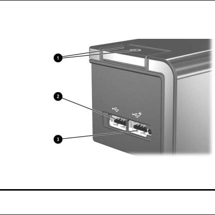
The external components on the left side of the docking station are shown in the following illustration and described in Table 1-3.
Left-Side Components, Docking Station
Table 1-3
Left-Side Components, Docking Station
Item |
Component |
Description |
|
|
|
1 |
Power button and |
Turns on power to the computer. The light |
|
power light |
indicates the state of the computer, and is |
|
|
turned on when the computer is turned on. |
|
|
|
2 |
USB port |
Allows you to connect USB devices. |
|
|
|
3 |
Powered USB port |
Allows you to connect to select USB |
|
|
devices. |
|
|
|
1–10 |
Maintenance and Service Guide |

Product Description
The external components on the left side of the advanced docking station are shown in the following illustration and described in Table 1-4.
Left-Side Components, Advanced Docking Station
Table 1-4
Left-Side Components, Advanced Docking Station
Item |
Component |
Description |
|
|
|
1 |
MultiBay II light |
Lights to indicate MultiBay II drive activity. |
|
|
|
2 |
MultiBay II |
Supports 9.5-mm MultiBay II drives |
|
|
such as hard drives and optical drives. |
|
|
|
3 |
USB ports (3) |
Allow you to connect USB devices. |
|
|
|
4 |
Powered USB port |
Allows you to connect to select USB |
|
|
devices. |
|
|
|
5 |
ExpressCard slot |
Allows you to connect ExpressCard |
|
|
devices to the docking station. |
|
|
|
6 |
Power button and |
Turns on power to the computer. The light is |
|
power light |
turned on when the computer is turned on. |
|
|
|
Maintenance and Service Guide |
1–11 |

Product Description
The external components on the right side of the docking station are shown in the following illustration and described in Table 1-5.
Right-Side Components, Docking Station
Table 1-5
Right-Side Components, Docking Station
Item |
Component |
Description |
|
|
|
1 |
Computer eject button |
Ejects the computer from the docking |
|
and dock light |
station. The dock light is turned on |
|
|
when the computer is properly aligned. |
|
|
|
2 |
Integrated cable lock slot |
Supports the cable lock, which secures |
|
|
the docking station and a connected |
|
|
computer. |
|
|
|
1–12 |
Maintenance and Service Guide |

Product Description
The external components on the right side of the advanced docking station are in the following illustration below and described in Table 1-6.
Right-Side Components, Advanced Docking Station
Table 1-6
Right-Side Components, Advanced Docking Station
Item |
Component |
Description |
|
|
|
1 |
Computer eject button |
Ejects the computer from the docking |
|
and docking light |
station. The docking light is turned on when |
|
|
the computer is properly aligned. |
|
|
|
2 |
Integrated cable lock slot |
Supports the cable lock, which secures the |
|
|
docking station, connected computer, and |
|
|
MultiBay II drive. |
|
|
|
Maintenance and Service Guide |
1–13 |
Product Description
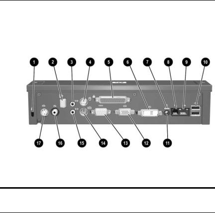
The external components on the rear of the docking station are shown in the following illustration and described in Table 1-7.
Rear Components, Docking Station
Table 1-7
Rear Components, Docking Station
Item |
Component |
Description |
|
|
|
1 |
Security cable slot |
Connects an optional security |
|
|
cable lock. |
|
|
|
2 |
Monitor stand port |
Connects an optional HP Monitor Stand |
|
|
to the docking station. |
|
|
|
3 |
Audio-out (headphone) jack |
Connects an audio output device such |
|
|
as headphones or speakers. |
|
|
|
4 |
Mouse connector |
Connects a PS/2 mouse. |
|
|
|
5 |
Parallel port |
Connects a parallel device such as |
|
|
a printer. |
|
|
|
6 |
Digital video (DVI) jack |
Connects a DVI device such as a flat |
|
|
panel monitor. |
|
|
|
1–14 |
Maintenance and Service Guide |

Product Description
Table 1-7
Rear Components, Docking Station (Continued)
Item |
Component |
Description |
|
|
|
7 |
Power light |
Is turned on when the docking station |
|
|
is connected to AC power. |
|
|
|
8 |
RJ-11 (modem) jack |
Connects a telephone cable. |
|
|
|
9 |
RJ-45 (network) jack |
Connects a network cable. |
|
|
|
10 |
USB ports (2) |
Connect USB devices. |
|
|
|
11 |
Smart Adapter power |
Connects the docking station to the |
|
connector |
HP Smart Adapter AC adapter. |
|
|
|
12 |
External monitor port |
Connects a VGA monitor. |
|
|
|
13 |
Serial port |
Connects a serial device such as |
|
|
a mouse. |
|
|
|
14 |
Keyboard connector |
Connects a PS/2 keyboard. |
|
|
|
15 |
Audio-in (microphone) jack |
Connects home audio equipment |
|
|
such as CD and MP3 players. |
|
|
|
16 |
Composite video jack |
Connects a composite video device |
|
|
such as a TV. |
|
|
|
17 |
S-Video-out jack |
Connects an S-Video device such |
|
|
as a TV, VCR, or camcorder. |
|
|
|
Maintenance and Service Guide |
1–15 |
 Laptop Docking Station User Manual")
Product Description
The external components on the rear of the advanced docking station are shown in the following illustration and described in Table 1-8.
Rear Components, Advanced Docking Station
Table 1-8
Rear Components, Advanced Docking Station
Item |
Component |
Description |
|
|
|
1 |
Security cable slot |
Connects an optional security cable lock. |
|
|
|
2 |
Audio-out (headphone) |
Connects an audio output device such as |
|
jack |
headphones or speakers. |
|
|
|
3 |
Mouse connector |
Connects a PS/2 mouse. |
|
|
|
4 |
Monitor stand port |
Connects an optional HP Monitor Stand to |
|
|
the docking station. |
|
|
|
1–16 |
Maintenance and Service Guide |
Product Description
Table 1-8
Rear Components, Advanced Docking Station (Continued)
Item |
Component |
Description |
|
|
|
5 |
Parallel port |
Connects a parallel device such as |
|
|
a printer. |
|
|
|
6 |
S-Video-out jack |
Connects an S-Video device such as a TV, |
|
|
VCR, or camcorder. |
|
|
|
7 |
Composite video jack |
Connects a composite video device such |
|
|
as a TV. |
|
|
|
8 |
Digital video (DVI) jack |
Connects a DVI device such as a flat panel |
|
|
monitor. |
|
|
|
9 |
Power light |
Is turned on when the docking station |
|
|
is connected to AC power. |
|
|
|
10 |
RJ-11 (modem) jack |
Connects a telephone cable. |
|
|
|
11 |
RJ-45 (network) jack |
Connects a network cable. |
|
|
|
12 |
USB ports (2) |
Connect USB devices. |
|
|
|
13 |
Smart Adapter power |
Connects the docking station to the |
|
connector |
HP Smart Adapter AC adapter. |
|
|
|
14 |
External monitor port |
Connects a VGA monitor. |
|
|
|
15 |
Serial port |
Connects a serial device such as a mouse. |
|
|
|
16 |
Keyboard connector |
Connects a PS/2 keyboard. |
|
|
|
17 |
Audio-in (microphone) |
Connects home audio equipment such as |
|
jack |
CD and MP3 players. |
|
|
|
Maintenance and Service Guide |
1–17 |
Loading...