


L200-002NFE2
Hitachi L200-002NFE2, L200-004NFE2, L200-002NFEF2, L200-002NFU2, L200-004NFEF2 Quick Reference Manual
...
• Single-phase Input 200V Class
• Three-phase Input 200V Class
• Three-phase Input 400V Class
Manual No. NB6751X • Sept. 2006
Hitachi Industrial Equipment Systems Co., Ltd.
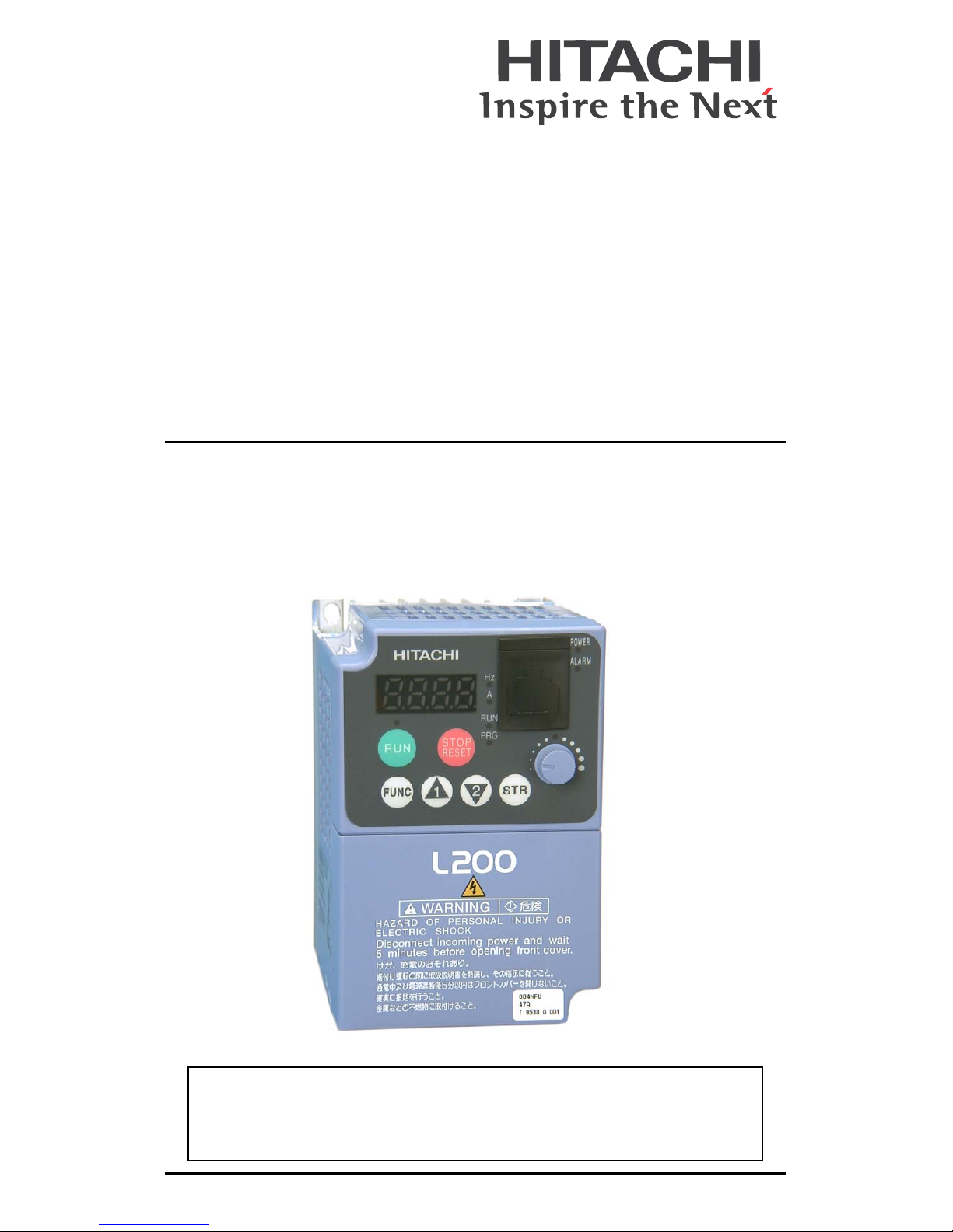
L2002 Series Inverter
Quick Reference Guide


1
Caution: Be sure to read the L2002 Inverter Manual and follow
its Cautions and Warnings for the initial product installation.
This Quick Reference Guide is intended for reference use by
experienced users in servicing existing installations.
UL® Cautions, Warnings, and Instructions
Wiring Warnings for Electrical Practices and Wire Sizes
The Cautions, Warnings, and instructions in this section summarize the
procedures necessary to ensure an inverter installation complies with
Underwriters Laboratories
®
guidelines.
Warnin g : “Use 60/75°C Cu wire only” or equivalent.
Warnin g : “Open Type Equipment.”
Warnin g : “Suitable for use on a circuit capable of delivering
not more than 100,000 rms symmetrical amperes, 240 V
maximum.” For models with suffix N or L.
Warnin g : “Suitable for use on a circuit capable of delivering
not more than 100,000 rms symmetrical amperes, 480 V
maximum.” For models with suffix H.
Warnin g : “Hot surface—risk of burn.”
Warnin g : “Install device in pollution degree 2 environment.”
Warnin g : “Maximum Surrounding Air Temperature 50°C.”
Warnin g : “Risk of electric shock—capacitor discharge time is at
least 5 minutes.”
Warnin g : “Solid state motor overload protection is provided in
each model.”
Warnin g : “Tightening torque and wire range for field wiring
terminals are marked adjacent to the terminal or on the wiring
diagram.”

2
Terminal Tightening Torque and Wire Size
The wire size range and tightening torque for field wiring terminals are
presented in the tables below.
200V Models
Motor output
Inverter Model
Wire Size
(AWG)
Torque
kW HP ft-lbs (N-m)
0.2 1/4 –002NFE(F)2/NFU2
16 0.6 0.80.4 1/2 –004NFE(F)2/NFU2
0.55 3/4 –005NFE(F)2
0.75 1 –007NFE(F)2/NFU2
14
0.9 1.2
1.1 1 1/2 –011NFE(F)2
1.5 2 –015NFE(F)2/NFU2 12
2.2 3 –022NFE(F)2/NFU2 10
3.7 5 –037LFU2 12
5.5 7 1/2 –055LFU2 10
1.5 2.0
7.5 10 –075LFU2 8
400V Models
Motor output
Inverter Model
Wire Size
(AWG)
Torque
kW HP ft-lbs (N-m)
0.4 1/2 –004HFE(F)2/HFU2
16
0.9 1.2
0.75 1 –007HFE(F)2/HFU2
1.5 2 –015HFE(F)2/HFU2
2.2 3 –022HFE(F)2/HFU2
3.0 4 –030HFE(F)2 14
4.0 5 –040HFE(F)2/HFU2
5.5 7 1/2 –055HFE(F)2/HFU2 12 1.5 2.0
7.5 10 –075HFE(F)2/HFU2

3
Wire Connectors
Warnin g : Field wiring connections
must be made by a UL Listed and CSA
Certified ring lug terminal connector
sized for the wire gauge being used.
The connector must be fixed using the
crimping tool specified by the connector manufacturer.
Fuse and Circuit Breaker Sizes
The inverter’s input power wiring must include UL Listed, dual-element,
600V fuses, or UL Listed, inverse-time, 600V circuit breakers.
Terminal Connector
Wire Size
Range
(AWG)
Torque Range
ft-lbs (N-m)
Logic/Analog connector 30—16 0.16—0.19 0.22—0.25
Relay connector 30—14 0.37—0.44 0.5—0.6
200V Models
Motor output
Inverter Model
Ampere Rating for
Fuse or Breaker
kW HP
0.2 1/4 –002NFE(F)2/NFU2 10
0.4 1/2 –004NFE(F)2/NFU2 10
0.55 3/4 –005NFE(F)2 10
0.75 1 –007NFE(F)2/NFU2 15
1.1 1 1/2 –011NFE(F)2 15
1.5 2 –015NFE(F)2/NFU2 20 (single ph.)
15 (three ph.)
2.2 3 –022NFE(F)2/NFU2 30 (single ph.)
20 (three ph.)
3.7 5 –037LFU2 30
5.5 7 1/2 –055LFU2 40
7.5 10 –075LFU2 50
Terminal (ring lug)
Cable support
Cable
4
Motor Overload Protection
Hitachi L2002 inverters provide solid state motor overload protection,
which depends on the proper setting of the following parameters:
• B012 “electronic overload protection”
• B212 “electronic overload protection, 2nd motor”
Set the rated current [Amperes] of the motor(s) with the above parameters. The setting range is 0.2 * rated current to 1.2 * rated current.
Warning : When two or more motors are connected to the
inverter, they cannot be protected by the electronic overload protection. Install an external thermal relay on each motor.
400V Models
Motor output
Inverter Model
Ampere Rating for
Fuse or Breaker
kW HP
0.4 1/2 –004HFE(F)2/HFU2 3
0.75 1 –007HFE(F)2/HFU2 6
1.5 2 –015HFE(F)2/HFU2 10
2.2 3 –022HFE(F)2/HFU2 10
3.0 4 –030HFE(F)2 15
4.0 5 –040HFE(F)2/HFU2 15
5.5 7 1/2 –055HFE(F)2/HFU2 20
7.5 10 –075HFE(F)2/HFU2 25

5
Power Circuit Terminals
Inverter models L200–002NFE(F)2/NFU2, –004NFE(F)2/
NFU2, –005NFE(F)2
Jumper
+1
+ –
U/T1
V/T2
W/T3
Chassis
Ground
Inverter models L200–007NFE(F)2/NFU2 to –022NFE(F)2/
NFU2, –037LFU2, –004HFE(F)2/HFU2 to –040HFE(F)2/
HFU2
Inverter models L200–055LFU2,, –055HFE2/HFU2,
–075LFU2, –075HFE2/HFU2
L1 L2 N/L3
Jumper
+ –
U/T1 V/T2 W/T3
Chassis
Ground
+1
L1 L2 N/L3
R/L1 S/L2 T/L3
NFE(F)2,
NFU2
LFU2,
HFE(F)2,
HFU2
U/T1 V/T2 W/T3
Jumper
P/+ N/–
PD/+1
Chassis
Ground
U/T1R/L1 S/L2 T/L3 V/T2 W/T3

6
Control Circuit Terminals
Ter mina l
Name
Description Ratings and Notes
PCS +24V for logic inputs 24VDC supply, 30 mA max.
(Notes: Do not use for network
power
Do not short to terminal L)
1, 2, 3, 4, 5Intelligent (program-
mable) discrete logic
inputs
27VDC max. (use P24 or an
external supply referenced to
terminal L), 4.7kΩ input
impedance
Inverter models L200–HFEF2, –075HFEF2
Jumper
+ –
+1
Chassis
Ground
U/T1 V/T2 W/T3L1 L2 L3
H O OI
PCS
L
Analog
inputs
Analog
output
Alarm relay
Logic
outputs
Logic inputs
L 5 4 3 2 1
CM2
12 11
AL2 AL1 AL0
AM

7
L (right) GND for logic inputs Sum of input 1 to 5 currents
(Note: Do not ground)
11, 12 Discrete logic outputs 50 mA max. ON current,
27 VDC max. OFF voltage
CM2 GND for logic outputs 100 mA max for sum of
terminals 11 and 12 currents
AM Analog voltage output 0 to 10VDC, 1 mA max., 50%
duty cycle
L (left) GND for analog signals Sum of OI, O, H, and AM
currents (return)
OI Analog input, current 4 to 19.6 mA range, 20 mA
nominal
O Analog input, voltage 0 to 9.6 VDC range, 10VDC
nominal, 12VDC max., input
impedance 10 kΩ
H +10V analog reference 10VDC nominal, 10 mA max.
AL0 Relay common contact
Contact rating
Max resistive load = 250VAC,
2.5A; 30VDC 3A;
Max inductive load = 250VAC,
0.2A; 30VDC 0.7A
Minimum load = 5VDC 100mA,
100VAC 10mA
AL1 Relay contact, normally
closed during RUN
AL2 Relay contact, normally
open during RUN
Terminal
Name
Description Ratings and Notes

8
Basic Wiring Diagram
The following wiring diagram shows the power and motor connections
for basic operation. The optional signal input wiring supports external
Fwd and Rev Run command, and a speed potentiometer.
(L1)
R
(L2)
S
(N/L3)
T
(T2)
V
(T3)
W
(T1)
U
Motor
Forward
L
O
H
Reverse
Relay contacts,
1 Form C
Run signal
Frequency
arrival signal
Open collector
outputs:
External
speed
reference
pot.
L200
From 3-phase
power input
source (See
specifications
label on inverter
for details)
Load
Load
Analog reference
PCS
2
1
CM2
12
11
AL0
AL1
AL2
Inputs:
L
GND for logic inputs
GND for logic
outputs
GND for analog signals
9
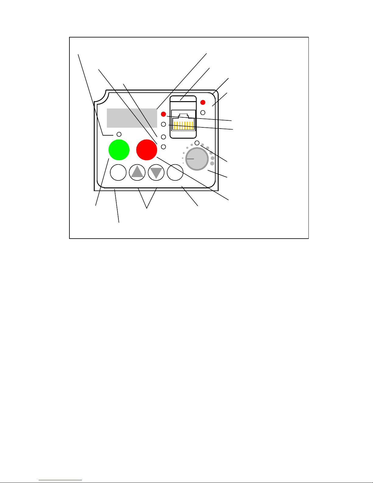
Inverter Keypad Operation
• Run/Stop LED – ON when the inverter output is ON and the motor is
developing torque, and OFF when the inverter output is OFF (Stop
Mode).
• Program/Monitor LED – ON when the inverter is ready for parame-
ter editing (Program Mode). It is OFF when the parameter display is
monitoring data (Monitor Mode).
• Run Key Enable LED – ON when the inverter is ready to respond to
the Run key, OFF when the Run key is disabled.
• Run Key – Press this key to run the motor (the Run Enable LED must
be ON first). Parameter F004, Keypad Run Key Routing, determines
whether the Run key generates a Run FWD or Run REV command.
• Stop/Reset Key – Press this key to stop the motor when it is running
(uses the programmed deceleration rate). This key will also reset an
alarm which has tripped.
• Potentiometer – Allows an operator to directly set the motor speed
when the potentiometer is enabled for output frequency control.
• Potentiometer Enable LED – ON when the potentiometer is enabled
for value entry.
(continued, next page...)
1
2
50.0
Parameter Display
Run/Stop LED
Program/Monitor LED
Run Key Enable LED
Run Key
Power LED
Display Units LEDs
Hertz
Amperes
Potentiometer
Enable LED
Potentiometer
Stop/Reset Key
Function Key
Up/Down Keys
Store Key
Alarm LED
Serial Port
RUN
STOP
RESET
FUNC.
STR
HITACHI
POWER
ALARM
RUN
A
Hz
PRG
 Loading...