


Planer
Hobel
Rabot
Pialletto
Schaafmachine
Cepillo
P 20SA2
Read through carefully and understand these instructions before use.
Diese Anleitung vor Benutzung des Werkzeugs sorgfältig durchlesen und verstehen. Lire soigneusement et bien assimiler ces instructions avant usage.
Prima dell’uso leggere attentamente e comprendere queste istruzioni. Deze gebruiksaanwijzing s.v.p. voor gebruik zorgvuldig doorlezen. Leer cuidadosamente y comprender estas instrucciones antes del uso.
Handling instructions
Bedienungsanleitung
Mode d’emploi
Istruzioni per l’uso
Gebruiksaanwijzing
Instrucciones de manejo

1 |
1 |
2 |
2 |
3 |
3 |
|
|
|
82mm (Max) |
11mm (Max) |
25mm (Max) |
|
||
|
|
|
|
11mm (Max) |
|
4 |
4 |
5 |
|
|
5
25mm (Max) |
6 |
|
6
8
 0
0
7
7 8 9 B
9 |
A |
= |
|
||
|
|
10 |
11 |
12 |
B
D
1
13 |
|
14 |
|
|
15 |
|
|
0 |
|
|
|
|
|
C |
|
|
|
|
|
|
|
|
E |
|
A |
|
|
D |
|
16 |
|
17 |
|
|
18 |
D |
B |
N |
|
J |
|
G |
|
|
|
||
|
H |
|
|
||
F |
|
|
G |
|
|
|
|
|
|
|
|
|
I |
|
|
|
K |
19 |
A |
20 |
G |
L |
21 |
|
1mm L |
1mm |
C |
K |
M |
|
22 |
A |
23 |
|
|
24 |
|
|
|
|
L |
|
|
|
|
G |
N |
H |
|
|
|
|
||
|
|
F |
|
|
|
|
|
|
|
|
|
|
C |
|
|
I |
L |
|
|
|
|
2

25 |
26 |
|
|
|
|
|
|
|
|
|
|
O |
|
|
|
|
|
|
|
|
|
|
|
|
21 |
|
|
|
|
|
|
|
|
|
|
|
|
5 mm |
|
||
|
|
|
12 mm |
|
||
|
|
|
|
|
P |
|
|
|
|
|
|
|
|
|
English |
|
|
|
Deutsch |
Français |
|
|
|
|
|
||
1 |
Planing |
|
Hobeln |
Rabotage |
||
2 |
Beveling |
|
Abkanten |
Biseautage |
||
3 |
Rabbeting |
|
Falzen |
Formation de feuillure |
||
4 |
Tapering |
|
Abschrägen |
Formation de biais |
||
5 |
Knob |
|
Knopf |
Bouton |
||
6 |
Scale |
|
Skala |
Échelle |
||
7 |
Mark |
|
Markierung |
Marque |
||
8 |
Beginning of cutting operation |
|
Beginn des Hobelns |
Début de l’opération de coupe |
||
9 |
End of cutting operation |
|
Ende des Hobelns |
Fin de l’opération de coupe |
||
; |
Box wrench |
|
Steckschlüssel |
Clef à béquille |
||
A |
Blade holder |
|
Hobeleisenhalter |
Support de lame |
||
|
Carbide blade |
|
Hobeleisen mit |
Lame au carbure |
||
B |
|
Hartmetallschneide |
||||
|
(Double edged blade type) |
|
(Beidseitigen Klingentyp) |
(Lames à deux tranchants) |
||
|
|
|
|
|||
C |
Bolt |
|
Schraube |
Boulon |
||
D |
Set plate (B) |
|
Einstellplatte (B) |
Plaque de fixation (B) |
||
E |
Machine screw |
|
Maschinenschraube |
Vis machine |
||
F |
Turned surface |
|
Gebogene Oberfläche |
Surface tournée |
||
G |
Set plate (A) |
|
Einstellplatte (A) |
Plaque de fixation (A) |
||
H |
Set gauge |
|
Einstell-Lehre |
Jauge de fixation |
||
I |
Wall surface b |
|
Wandoberfläche b |
Surface du mur b |
||
J |
Flat portion of the cutter block |
|
Flacher Teil des Schneidblocks |
Section plate du bloc de lame |
||
K |
Groove |
|
Nut |
Encoche |
||
L |
Blade (Resharpenable blade type) |
|
Hobeleisen |
Lame (lame de type réaffûtable) |
||
|
(schärfbarer Klingentyp) |
|||||
|
|
|
|
|||
M |
Cutter block |
|
Schneidblock |
Bloc de coupe |
||
N |
Wall surface a |
|
Wandoberfläche a |
Surface du mur a |
||
O |
Wear limit |
|
Verschleißgrenze |
Limite d’usure |
||
P |
No. of carbon brush |
|
Nr. der Kohlebürste |
N˚ du balai en carbone |
||
|
|
|
|
|
|
|
3
|
Italiano |
Nederlands |
Español |
|
|
|
|
|
|
1 |
Piallatura |
Schaven |
Cepillar |
|
|
|
|
|
|
2 |
Smussatura |
Afbramen |
Biselar |
|
3 |
Scanalatura |
Groeven |
Ensamblar |
|
4 |
Rastrematura |
Afschuinen |
Renatar |
|
5 |
Manopola |
Knop |
Botón |
|
6 |
Scala graduata |
Schaal |
Escala |
|
7 |
Segno |
Merkteken |
Marca |
|
8 |
Inizio dell’operazione di piallatura |
Begin van het schaven |
Principio de la operación de |
|
corte |
||||
|
|
|
||
9 |
Termine dell’operazione di |
Einde van het schaven |
Fin de la operación de corte |
|
|
piallatura |
|
|
|
; |
Chiave fissa a collare |
Steeksleutel |
Llave anular |
|
A |
Porta-lama |
Schaafijzerhouder |
Sujetador de cuchilla |
|
B |
Lama in carburo |
Koolstofmetaalmes |
Cuchilla de carburo |
|
|
(tipo lama a doppio filo) |
(Mes met dubbele rand) |
(Tipo de cuchilla de doble borde) |
|
C |
Bulloni |
Schroef |
Perno |
|
|
|
|
|
|
D |
Piastra di impostazione (B) |
Gemonteerde plaat (B) |
Placa de ajuste (B) |
|
|
|
|
|
|
E |
Vite |
Machineschroef |
Tornillo de máquina |
|
|
|
|
|
|
F |
Superficie curva |
Gedraaid oppervlak |
Superficie girada |
|
|
|
|
|
|
G |
Piastra di impostazione (A) |
Gemonteerde plaat (A) |
Placa de ajuste (A) |
|
H |
Calibro di impostazione |
Gemonteerd meetinstrument |
Manómetro de ajuste |
|
I |
Superficie parete b |
Muuroppervlak b |
Superficie de pared b |
|
J |
Parte piatta del blocco taglierina |
Vlakke gedeelte van freeszwart |
Parte plana del bloque del |
|
cortador |
||||
|
|
|
||
K |
Scanalatura |
Groef |
Ranura |
|
|
|
|
|
|
L |
Lama (tipo lama riaffilabile) |
Mes (Slijpbaar mes) |
Cuchilla (Tipo de cuchilla afilable) |
|
|
|
|
|
|
M |
Blocco della pialla |
Snijkop |
Bloque del cortador |
|
|
|
|
|
|
N |
Superficia parete a |
Muuroppervlak a |
Superficie de pared a |
|
|
|
|
|
|
O |
Limite di usura |
Slijtagegrens |
Límite de uso |
|
|
|
|
|
|
P |
N. della spazzola di carbone |
Nr. van de koolborstel |
N° de carbón de contacto |
|
|
|
|
|
4

English
GENERAL SAFETY RULES
WARNING!
Read all instructions
Failure to follow all instructions listed below may result in electric shock, fire and/or serious injury.
The term “power tool” in all of the warnings listed below refers to your mains operated (corded) power tool or battery operated (cordless) power tool.
SAVE THESE INSTRUCTIONS
1)Work area
a)Keep work area clean and well lit.
Cluttered and dark areas invite accidents.
b)Do not operate power tools in explosive atmospheres, such as in the presence of flammable liquids, gases or dust.
Power tools create sparks which may ignite the dust of fumes.
c)Keep children and bystanders away while operating a power tool.
Distractions can cause you to lose control.
2)Electrical safety
a)Power tool plugs must match the outlet. Never modify the plug in any way.
Do not use any adapter plugs with earthed (grounded) power tools.
Unmodified plugs and matching outlets will reduce risk of electric shock.
b)Avoid body contact with earthed or grounded surfaces such as pipes, radiators, ranges and refrigerators.
There is an increased risk of electric shock if your body is earthed or grounded.
c)Do not expose power tools to rain or wet conditions.
Water entering a power tool will increase the risk of electric shock.
d)Do not abuse the cord. Never use the cord for carrying, pulling or unplugging the power tool. Keep cord away from heat, oil, sharp edges or moving parts.
Damaged or entangled cords increase the risk of electric shock.
e)When operating a power tool outdoors, use an extension cord suitable for outdoor use.
Use of a cord suitable for outdoor use reduces the risk of electric shock
3)Personal safety
a)Stay alert, watch what you are doing and use common sense when operating a power tool. Do not use a power tool while you are tired or under the influence of drugs, alcohol or medication.
A moment of inattention while operating power tools may result in serious personal injury.
b)Use safety equipment. Always wear eye protection.
Safety equipment such as dust mask, non-skid safety shoes, hard hat, or hearing protection used for appropriate conditions will reduce personal injuries.
c)Avoid accidental starting. Ensure the switch is in the off position before plugging in.
Carrying power tools with your finger on the switch or plugging in power tools that have the switch on invites accidents.
d)Remove any adjusting key or wrench before turning the power tool on.
A wrench or a key left attached to a rotating part of the power tool may result in personal injury.
e)Do not overreach. Keep proper footing and balance at all times.
This enables better control of the power tool in unexpected situations.
f)Dress properly. Do not wear loose clothing or jewellery. Keep your hair, clothing and gloves away from moving parts.
Loose clothes, jewellery or long hair can be caught in moving parts.
g)If devices are provided for the connection of dust extraction and collection facilities, ensure these are connected and properly used.
Use of these devices can reduce dust related hazards.
4)Power tool use and care
a)Do not force the power tool. Use the correct power tool for your application.
The correct power tool will do the job better and safer at the rate for which it was designed.
b)Do not use the power tool if the switch does not turn it on and off.
Any power tool that cannot be controlled with the switch is dangerous and must be repaired.
c)Disconnect the plug from the power source before making any adjustments, changing accessories, or storing power tools.
Such preventive safety measures reduce the risk of starting the power tool accidentally.
d)Store idle power tools out of the reach of children and do not allow persons unfamiliar with the power tool or these instructions to operate the power tool.
Power tools are dangerous in the hands of untrained users.
e)Maintain power tools. Check for misalignment or binding of moving parts, breakage of parts and any other condition that may affect the power tools operation.
If damaged, have the power tool repaired before use.
Many accidents are caused by poorly maintained power tools.
f)Keep cutting tools sharp and clean.
Properly maintained cutting tools with sharp cutting edges are less likely to bind and are easier to control.
g)Use the power tool, accessories and tool bits etc., in accordance with these instructions and in the manner intended for the particular type of power tool, taking into account the working conditions and the work to be performed.
Use of the power tool for operations different from intended could result in a hazardous situation.
5)Service
a)Have your power tool serviced by a qualified repair person using only identical replacement parts.
This will ensure that the safety of the power tool is maintained.
PRECAUTION
Keep children and infirm persons away.
When not in use, tools should be stored out of reach of children and infirm persons.
5

English
Planer Safety Rules
Wait for the cutter to stop before setting the tool down.
An exposed cutter may engage the surface leading to possible loss of control and serious injury.
PRECAUTIONS ON USING PLANER
Do not use the Planer with the blades facing upward (as stationary type planer).
SPECIFICATIONS
Use dust collection adapter if need to reduce dust related hazards.
(1)Unscrew the Chip guide (Item no. 17 show in assembly drawing) on housing.
(2)Mount dust collection adapter on housing with screws instead of the Chip guide.
Dust collection adapter (Code no. 317279)
(3)Connect the dust extraction and collection facilities with the tube of dust collection adapter firmly.
Voltage (by areas)* |
(110V, 115V, 120V, 127V, 220V, 230V, 240V) |
Power Input |
720W* |
Cutting Width |
82mm |
Max. Cutting Depth |
3mm |
Weight (without cord and guide) |
3.0kg |
No-Load Speed |
14000/min |
|
|
* Be sure to check the nameplate on product as it is subject to change by areas.
STANDARD ACCESSORIES |
|
|
1. |
Box Wrench (for securing cutter blade) ............. |
1 |
2. |
Set Gauge (for adjusting cutter height) .............. |
1 |
3. |
Guide (with set screw) ........................................... |
1 |
4. |
Depth Guide .............................................................. |
1 |
5. |
Blade Sharpening Ass'y |
|
|
(for Resharpenable Blade Type) .......................... |
1 |
Standard accessories are subject to change without notice. |
||
OPTIONAL ACCESSORIES (sold separately)
1. Dust collection adapter (Code no. 317279) Optional accessories are subject to change without notice.
APPLICATIONS
Planing various wooden planks and panels. (See Fig. 1-4)
PRIOR TO OPERATION
1.Power source
Ensure that the power source to be utilized conforms to the power requirements specified on the product nameplate.
2.Power switch
Ensure that the power switch is in the OFF position. If the plug is connected to a receptacle while the power switch is in the ON position, the power tool will start operating immediately, which could cause a serious accident.
3.Extension cord
When the work area is removed from the power source, use an extension cord of sufficient thickness and rated capacity. The extension cord should be kept as short as practicable.
4.Prepare a stable wooden workbench suitable for planing operation. As a poorly balanced workbench
creates a hazard, ensure it is securely positioned on firm, level ground.
PLANING PROCEDURES
1. Adjusting the cutter depth:
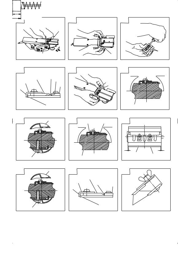
(1)Turn the knob in the direction indicated by the arrow in Fig. 5 (clockwise), until the triangular mark is aligned with the desired cutting depth on the scale. The scale unit is graduated in millimeters.
(2)The cutting depth can be adjusted within a range of 0-3mm.
2.Surface cutting:
Rough cutting should be accomplished at large cutting depths and at a suitable speed so that shavings are smoothly ejected from the machine. To ensure a smoothly finished surface, finish cutting should be accomplished at small cutting depths and at low feeding speed.
3.Beginning and ending the cutting operation:
As shown in Fig. 6, place the front base of the planer on the material and support the planer horizontally. Turn ON the power switch, and slowly operate the planer toward the leading edge of the material. Firmly depress the front half of the planer at the first stage of cutting, as shown in Fig. 7, depress the rear half of the planer at the end of the cutting operation. The planer must always be kept flat throughout the entire cutting operation.
4.Precaution after finishing the planing operation:
When the planer is suspended with one hand after finishing the planing operation, ensure that the cutting blades (base) of the planer do not contact or come too near your body. Failure to do so could result in serious injury.
6

English
CARBIDE BLADE ASSEMBLY AND DISASSEMBLY AND ADJUSTMENT OF CUTTER BLADE HEIGHT (FOR DOUBLE EDGED BLADE TYPE)
1. Carbide blade disassembly:
(1)As shown in Fig. 8, loosen the blade holder with the attached box wrench.
(2)As shown in Fig. 9, remove the carbide blade by sliding it with the attached box wrench.
CAUTION
Be careful not to injure your hands.
2.Carbide blade assembly:
CAUTION
Prior to assembly, thoroughly wipe off all swarf accumulated on the carbide blade.
(1)As shown in Fig. 10, lift set plate (B) and insert the new carbide blade between cutter block and set plate (B).
(2)As shown in Fig. 11, mount the new carbide blade by sliding it on the set plate (B) so that the blade tip projects by 1mm from the end of the cutter block.
(3)As shown in Fig. 12, fix the bolts at the blade holder after blade replacement has been completed.
(4)Turn the cutter block over, and set the other side in the same manner.
3. Adjustment of carbide blade height: CAUTION
If the carbide blade’s heights are inaccurate after above procedures have been completed, carry out the procedures described below.
(1)As shown in Fig. 13, use the box wrench to loosen the three bolts used to retain the carbide blade, and remove the blade holder.
(2)As shown in Fig. 14, after removing the carbide blade, slide set plate (B) in the direction indicated by the arrow to disassemble set plate (B).
(3)Loosen the 2 screws holding on the carbide blade and set plate (A), set plate (B).
(4)As shown in Fig. 15, 16, press the turned surface of set plate (A) to the wall surface b while adjusting the carbide blade edge to the wall surface a of the set gauge. Then, tighten them with the 2 screws.
(5)As shown in Fig. 17, 18, insert a turned portion of set plate (A) attached to set plate (B) into a groove on the flat portion of the cutter block.
(6)As shown in Fig. 19, place the blade holder on the completed assembly and fasten it with the three bolts. Ensure that the bolts are securely tightened. Follow the same procedures for the opposite side carbide blade.
BLADE ASSEMBLY AND DISASSEMBLY AND ADJUSTMENT OF BLADE HEIGHT (FOR RESHARPENABLE BLADE TYPE)
1. Blade disassembly:
(1)As shown in Fig. 13, use the accessory box wrench to loosen the three bolts used to retain the blade, and remove the blade holder.
(2)As shown in Fig. 14, slide the blade in the direction indicated by the arrow to disassemble the blade.
CAUTION
Be careful not to injure your hands.
2. Blade assembly: CAUTION
Prior to assembly, thoroughly wipe off all swarf accumulated on the blade.
(1)Insert a turned portion of set plate (A) attached to the blade into a groove on the flat portion of the cutter block. (Fig. 17, 20)
Set the blade so that both sides of the blade protrude from the width of the cutter block by about 1 mm (Fig. 21)
(2)Place the blade holder on the completed assembly, as shown in Fig. 22, and fasten it with the three bolts. Ensure that the bolts are securely tightened.
(3)Turn the cutter block over, and set the opposite side in the same manner.
3. Adjustment of blade height:
(1)Loosen the 2 screws holding on the blade and set plate (A).
(2)Press the turned surface of set plate (A) to the wall surface b while adjusting the blade edge to the wall surface a of the set gauge. Then, tighten them with the 2 screws. (Fig. 15, 23)
SHARPENING THE RESHARPENABLE BLADES
Use of the accessory Blade Sharpening Ass'y is recommended for convenience.
1.Use of Blade Sharpening Ass'y
As shown in Fig. 24, two blades can be mounted on the blade sharpening ass'y to ensure that the blade tips are ground at uniform angles. During grinding, adjust the position of the blades so that their edges simultaneously contact the dressing stone as shown in Fig. 25.
2.Blade sharpening intervals
Blade sharpening intervals depend on the type of wood being cut and the cutting depth. However, sharpening should generally be effected after each 500 meters of cutting operation.
3.Dressing Stone
When a water dressing stone is available, use it after dipping it sufficiently in water since such a dressing stone may be worn during grinding works, flatten the upper surface of the dressing stone as often as necessary.
MAINTENANCE AND INSPECTION
1.Inspecting the blades:
Continued use of dull or damaged blades will result in reduced cutting efficiency and may cause overloading of the motor. Sharpen or replace the blades as often as necessary.
2.Handling:
CAUTION
The front base, rear base, and cutting depth control knob are precisely machined to obtain specifically high precision. If these parts are roughly handled or subjected to heavy mechanical impact, it may cause deteriorated precision and reduced cutting performance. These parts must be handled with particular care.
7

English
3.Inspecting the mounting screws:
Regularly inspect all mounting screws and ensure that they are properly tightened. Should any of the screws be loose, retighten them immediately. Failure to do so could result in serious hazard.
4.Inspecting the carbon brushes: (Fig. 26)
The motor employs carbon brushes which are consumable parts. Since an excessively worn carbon brush can result in motor trouble, replace the carbon brushes with new ones having the same carbon brush No. shown in the figure when it becomes worn to or near the “wear limit”. In addition, always keep carbon brushes clean and ensure that they slide freely within the brush holders.
5.Replacing carbon brushes:
After removing the chip cover, use a slotted screwdriver to disassemble the brush caps. The carbon brushes can then be easily removed with the spring.
6.Maintenance of the motor:
The motor unit winding is the very “heart” of the power tool.
Exercise due care to ensure the winding does not become damaged and/or wet with oil or water.
NOTE
Due to HITACHI’s continuing program of research and development, the specifications herein are subject to change without prior notice.
IMPORTANT
Correct connection of the plug
The wires of the main lead are coloured in accordance with the following code:
Blue: -- Neutral Brown: -- Live
As the colours of the wires in the main lead of this tool may not correspond with the coloured markings identifying the terminals in your plug proceed as follows: The wire coloured blue must be connected to the terminal marked with the letter N or coloured black.
The wire coloured brown must be connected to the terminal marked with the letter L or coloured red. Neither core must be connected to the earth terminal.
NOTE
This requirement is provided according to BRITISH STANDARD 2769: 1984.
Therefore, the letter code and colour code may not be applicable to other markets except The United Kingdom.
Information concerning airborne noise and vibration
The measured values were determined according to
EN 60745 and declared in accordance with ISO 4871.
Measured A-weighted sound power level: 100 dB (A)
Measured A-weighted sound pressure level: 89 dB (A)
Uncertainty KpA: 3 dB (A)
Wear ear protection.
The typical weighted root mean square acceleration value does not exceed 2.5 m/s2.
8

Deutsch
ALLGEMEINE SICHERHEITSMASSNAHMEN
WARNUNG!
Lesen Sie sämtliche Hinweise durch
Wenn nicht sämtliche nachstehenden Anweisungen befolgt werden, kann es zu Stromschlag, Brand und/oder ernsthaften Verletzungen kommen.
Der Begriff „Elektrowerkzeug“ bezieht sich in den folgenden Warnhinweisen auf Elektrowerkzeuge mit Netz- (schnurgebunden) oder Akkubetrieb (schnurlos).
BEWAHREN SIE DIESE ANWEISUNGEN AUF
1)Arbeitsbereich
a)Sorgen Sie für einen sauberen und gut ausgeleuchteten Arbeitsbereich.
Zugestellte und dunkle Bereiche ziehen Unfälle förmlich an.
b)Verwenden Sie Elektrowerkzeuge niemals an Orten, an denen Explosionsgefahr besteht – zum Beispiel in der Nähe von leicht entflammbaren Flüssigkeiten, Gasen oder Stäuben.
Bei der Arbeit mit Elektrowerkzeugen kann es zu Funkenbildung kommen, wodurch sich Stäube oder Dämpfe entzünden können.
c)Sorgen Sie bei der Arbeit mit Elektrowerkzeugen dafür, dass sich keine Zuschauer (insbesondere Kinder) in der Nähe befinden.
Wenn Sie abgelenkt werden, können Sie die Kontrolle über das Werkzeug verlieren.
2)Elektrische Sicherheit
a)Elektrowerkzeuge müssen mit passender Stromversorgung betrieben werden.
Nehmen Sie niemals irgendwelche Änderungen am Anschlussstecker vor.
Verwenden Sie bei Elektrowerkzeugen mit Schutzkontakt (geerdet) niemals Adapterstecker.
Stecker im Originalzustand und passende Steckdosen reduzieren das Stromschlagrisiko.
b)Vermeiden Sie Körperkontakt mit geerdeten Gegenständen wie Rohrleitungen, Heizungen, Herden oder Kühlschränken.
Bei Körperkontakt mit geerdeten Gegenständen besteht ein erhöhtes Stromschlagrisiko.
c)Setzen Sie Elektrowerkzeuge niemals Regen oder sonstiger Feuchtigkeit aus.
Wenn Flüssigkeiten in ein Elektrowerkzeug eindringen, erhöht sich das Stromschlagrisiko.
d)Verwenden Sie die Anschlussschnur nicht missbräuchlich. Tragen Sie das Elektrowerkzeug niemals an der Anschlussschnur, ziehen Sie es nicht damit heran und ziehen Sie den Stecker nicht an der Anschlussschnur aus der Steckdose. Halten Sie die Anschlussschnur von Hitzequellen, Öl, scharfen Kanten und beweglichen Teilen fern.
Beschädigte oder verdrehte Anschlussschnüre erhöhen das Stromschlagrisiko.
e)Wenn Sie ein Elektrowerkzeug im Freien benutzen, verwenden Sie ein für den Außeneinsatz geeignetes Verlängerungskabel.
Ein für den Außeneinsatz geeignetes Kabel vermindert das Stromschlagrisiko.
3)Persönliche Sicherheit
a)Bleiben Sie wachsam, achten Sie auf das, was Sie tun, und setzen Sie Ihren Verstand ein, wenn Sie mit Elektrowerkzeugen arbeiten.
Benutzen Sie keine Elektrowerkzeuge, wenn Sie müde sind oder unter Einfluss von Drogen, Alkohol oder Medikamenten stehen.
Bei der Arbeit mit Elektrowerkzeugen können bereits kurze Phasen der Unaufmerksamkeit zu schweren Verletzungen führen.
b)Benutzen Sie Schutzausrüstung. Tragen Sie immer einen Augenschutz.
Schutzausrüstung wie Staubmaske, rutschsichere Sicherheitsschuhe, Schutzhelm und Gehörschutz senken das Verletzungsrisiko bei angemessenem Einsatz.
c)Vermeiden Sie unbeabsichtigten Anlauf. Achten Sie darauf, dass sich der Schalter in der Aus- (Off-) Position befindet, ehe Sie den Stecker einstecken.
Das Herumtragen von Elektrowerkzeugen mit dem Finger am Schalter und das Einstecken des Steckers bei betätigtem Schalter zieht Unfälle regelrecht an.
d)Entfernen Sie sämtliche Einstellwerkzeuge (Einstellschlüssel), ehe Sie das Elektrowerkzeug einschalten.
Ein an einem beweglichen Teil des Elektrowerkzeugs angebrachter Schlüssel kann zu Verletzungen führen.
e)Sorgen Sie für einen festen Stand. Achten Sie jederzeit darauf, sicher zu stehen und das Gleichgewicht zu bewahren.
Dadurch haben Sie das Elektrowerkzeug in unerwarteten Situationen besser im Griff.
f)Kleiden Sie sich richtig. Tragen Sie keine lose Kleidung oder Schmuck. Halten Sie Haar, Kleidung und Handschuhe von beweglichen Teilen fern.
Lose Kleidung, Schmuck oder langes Haar kann von beweglichen Teilen erfasst werden.
g)Wenn Anschlüsse für Staubabsaugund - sammelvorrichtungen vorhanden sind, sorgen Sie dafür, dass diese richtig angeschlossen und eingesetzt werden.
Die Verwendung solcher Vorrichtungen kann Staub-bezogene Gefahren mindern.
4)Einsatz und Pflege von Elektrowerkzeugen
a)Überanspruchen Sie Elektrowerkzeuge nicht. Benutzen Sie das richtige Elektrowerkzeug für Ihren Einsatzzweck.
Das richtige Elektrowerkzeug erledigt seine Arbeit bei bestimmungsgemäßem Einsatz besser und sicherer.
b)Benutzen Sie das Elektrowerkzeug nicht, wenn es sich nicht am Schalter einund ausschalten lässt.
Jedes Elektrowerkzeug, das nicht mit dem Schalter betätigt werden kann, stellt eine Gefahr dar und muss repariert werden.
c)Ziehen Sie den Netzstecker, ehe Sie Einstellarbeiten vornehmen, Zubehörteile tauschen oder das Elektrowerkzeug verstauen.
Solche präventiven Sicherheitsmaßnahmen verhindern den unbeabsichtigten Anlauf des Elektrowerkzeugs und die damit verbundenen Gefahren.
9
Deutsch
d)Lagern Sie nicht benutzte Elektrowerkzeuge außerhalb der Reichweite von Kindern, lassen Sie nicht zu, dass Personen das Elektrowerkzeug bedienen, die nicht mit dem Werkzeug selbst und/oder diesen Anweisungen vertraut sind.
Elektrowerkzeuge in ungeschulten Händen sind gefährlich.
e)Halten Sie Elektrowerkzeuge in Stand. Prüfen Sie auf Fehlausrichtungen, sicheren Halt und Leichtgängigkeit beweglicher Teile, Beschädigungen von Teilen und auf jegliche andere Zustände, die sich auf den Betrieb des Elektrowerkzeugs auswirken können.
Bei Beschädigungen lassen Sie das Elektrowerkzeug reparieren, ehe Sie es benutzen.
Viele Unfälle mit Elektrowerkzeugen sind auf schlechte Wartung zurückzuführen.
f)Halten Sie Schneidwerkzeuge scharf und sauber.
Richtig gewartete Schneidwerkzeuge mit scharfen Schneidkanten bleiben weniger häufig hängen und sind einfacher zu beherrschen.
g)Benutzen Sie Elektrowerkzeuge, Zubehör, Werkzeugspitzen und Ähnliches in Übereinstimmung mit diesen Anweisungen und auf die für das jeweilige Elektrowerkzeug bestimmungsgemäße Weise – beachten Sie dabei die jeweiligen Arbeitsbedingungen und die Art und Weise der auszuführenden Arbeiten.
Der bestimmungswidrige Einsatz von Elektrowerkzeugen kann zu gefährlichen Situationen führen.
5)Service
a)Lassen Sie Elektrowerkzeuge durch qualifizierte Fachkräfte und unter Einsatz passender, zugelassener Originalteile warten.
TECHNISCHE DATEN
Dies sorgt dafür, dass die Sicherheit des Elektrowerkzeugs nicht beeinträchtigt wird.
VORSICHT
Von Kindern und gebrechlichen Personen fernhalten. Werkzeuge sollten bei Nichtgebrauch außerhalb der Reichweite von Kindern und gebrechlichen Personen aufbewahrt werden.
Sicherheitshinweise für Hobel
Warten Sie, bis das Schneidwerkzeug vollständig zum Stillstand gekommen ist, bevor Sie das Werkzeug ablegen.
Ein freiliegendes Schneidwerkzeug kann sich in die Oberfläche graben und zu Kontrollverlust über das Werkzeug und ernsthaften Verletzungen führen.
VORSICHTSMASSNAHMEN BEI DER BENUTZUNG DES HOBELS
Die Hobelmaschine nicht mit dem Messer nach oben verwenden (als stationäre Hobelmaschine maschine zu verwenden).
Verwenden Sie einen Staubfangadapter, falls anfallende Stäube zu Gefahren führen können.
(1)Schrauben Sie die Spanführung (Position 17 in der Übersichtszeichnung) vom Gehäuse ab.
(2)Montieren Sie den Staubfangadapter mit Hilfe von Schrauben statt der Spanführung am Gehäuse.
Staubfangadapter (Artikelnummer 317279)
(3)Verbinden Sie die Staubabsaugund Staubsammelgeräte per Schlauch fest und sicher mit dem Staubfangadapter.
Spannung (je nach Gebiet)* |
(110V, 115V, 120V, 127V, 220V, 230V, 240V) |
Leistungsaufnahme |
720W* |
Hobelbreite |
82mm |
Max. Spantiefe |
3mm |
Gewicht (ohne Kabel und Führung) |
3,0kg |
Leerlaufgeschwindigkeit |
14000 U/min |
|
|
* Vergessen Sie nicht, die Produktangaben auf |
dem Typenschild zu überprüfen, da sich diese |
||
je nach Verkaufsgebiet ändern. |
|
|
|
|
|
|
|
STANDARDZUBEHÖR |
|
SONDERZUBEHÖR (separat zu beziehen) |
|
|
|
|
|
|
|
|
|

Deutsch
VOR INBETRIEBNAHME
1.Netzspannung
Prüfen, ob die zu verwendende Netzspannung der Angabe auf dem Typenschild entspricht.
2.Netzschalter
Prüfen, ob der Netzschalter auf “AUS” steht. Wenn der Stecker an das Netz angeschlossen wird, während der Schalter auf “EIN” steht, beginnt das Werkzeug sofort zu laufen, was gefährlich wäre.
3.Verlängerungskabel
Wenn der Arbeitsbereich nicht in der Nähe des Netzanschlusses liegt, ist ein Verlängerungskabel ausreichenden Querschnitts und ausreichender Nennleistung zu verwende. Das Verlängerungskabel sollte so kurz wie möglich gehalten werden.
4.Es ist eine stabile hölzerne Arbeitsunterlage anzufertigen, die für Hobelarbeiten geeignet ist. Eine schlecht ausbalancierte Arbeitsunterlage bildet eine Gefahrenquelle. Es ist darauf zu achten, daß sie auf einem festen, ebenen Untergrund sicher aufgestellt ist.
HOBELARBEITEN
1. Einstellen der Spantiefe:
(1)Der Knopf wird in der durch den Pfeil in Abb. 5 (im Uhrzeigersinn) angedeuteten Richtung gedreht, bis das dreieckige Zeichen auf der Skala auf die gewünschte Spantiefe zeigt. Die Skala ist in mm abgestuft.
(2)Die Spantiefe in einem Bereich von 0-3mm, ingestellt werden.
2.Flächenhobeln:
Das Grobhobeln sollte mit großer Spantiefe und in einer geeigneten Geschwindigkeit durchgeführt werden, so daß die Hobelspäne gleichmäßig aus der Maschine ausgeworfen werden. Zur Erzielung einer glatten Oberfläche sollte das abschließende Hobeln mit geringer Spantiefe und niedriger Geschwindigkeit durchgeführt werden.
3.Beginn und Ende der Spanarbeiten:
Wie in Abb. 6 gezeigt, wird der vordere Teil des Hobels auf das Werkstück gesetzt und horizontal abgestützt. Der Motor wird eingeschaltet und der Hobel langsam zur Kante des Werkstücks vorgeschoben. Der vordere Teil des Hobels wird zu Beginn des Spanens, wie in Abb. 7 gezeigt, fest aufgedrückt, während zum Ende der Spanarbeit die hintere Hälfte des Hobels fest aufgedrückt wird. Der Hobel muß während der gesamten Hobelarbeit flach gehalten werden.
4.Vorsichtsmaßnahmen nach Beendigung der Hobelarbeiten:
Wenn der Hobel nach Beendigung der Hobelarbeit mit einer Hand abgenommen wird, ist darauf zu achten, daß das Hobeleisen (Unterseite) des Hobels nicht mit dem Körper in Berührung kommt. Sonst können ernsthafte Verletzungen entstehen.
EINUND AUSBAU DES HOBELEISENS UND EINSTELLEN DER SCHNEIDTIEFE (FÜR BEIDSEITIGEN KLINGENTYP)
1. Ausbau des Hobeleisens:
(1)Den Hobeleisenhalter mit Hartmetallshneide dem Steckschlüssel des Zubehörs wie in Abb. 8 gezeigt lösen.
(2)Das Hobeleisen wie in Abb. 9 gezeigt durch Schieben mit dem Steckschlüssel des Zubehörs entfernen.
ACHTUNG
Es ist darauf zu achten, daß man sich die Hände nicht verletzt.
2.Einbau des Hobeleisens mit Hartmetallschneide: ACHTUNG
Vor dem Einbau sorgfältig alle feinen Späne usw. vom Hobeleisen mit Hartmetallschneide
abwischen.
(1)Wie in Abb. 10 gezeigt, Einstellplatte (B) anheben und das neue Hobeleisen mit Hartmetallschneide zwischen Schneidblock und Einstellplatte (B) einschieben.
(2)Das neue Hobeleisen mit Hartmetallschneide wie in Abb. 11 gezeigt durch Verschieben auf der Einstellplatte (B) so anbringen, daß die Klingenspitze 1 mm über das Ende des Schneidblocks hervorsteht.
(3)Die Schrauben am Hobeleisenhalter wie in Abb. 12 gezeigt anziehen, nachdem das Hobeleisen ausgewechselt worden ist.
(4)Der Messerkopf wird umgedreht und die andere Seite auf die gleiche Weise befestigt.
3.Einstellen der Höhe des Hobeleisens mit Hartmetallschneide:
ACHTUNG
Wenn die Höhe der Hartmetallschneide nach Beendigung der obigen Verfahren nicht genau ist, die nachfolgend beschriebenen Verfahren durchführen.
(1)Den Steckschlüssel wie in Abb. 13 gezeigt verwenden, um die drei Schrauben zu lösen, die das Hobeleisen mit Hartmetallschneide halten, und dann den Hobeleisenhalter entfernen.
(2)Nach Entfernen des Hobeleisens mit Hartmetallschneide die Einstellplatte (B) wie in Abb. 14 gezeigt in Pfeilrichtung schieben, um die Einstellplatte (B) auszubauen.
(3)Die zwei Schrauben Lösen, die das Hobeleisen mit Hartmetallschneide auf der Einstellplatte (A) und der Einstellplatte (B) halten.
(4)Die gebogene Oberfläche der Einstellplatte (A) wie in Abb. 15 und 16 gezeigt zur Wandoberfläche b drücken, während die Kante des Hobeleisens mit Hartmetallschneide auf die Wandoberfläche a der Einstell-Lehre ausgerichtet wird. Dann mit den beiden Schrauben anziehen.
(5)Den gebogenen Teil der an der Einstellpaltte (B) angebrachten Einstellplatte (A) wie in Abb. 17 und 18 gezeigt am flachen Teil des Schneidblocks einschieben.
(6)Den Hobeleisenhalter wie in Abb. 19 gezeigt auf die fertige Montage setzen und ihn mit den drei Schrauben befestigen. Sicherstellen, daß die Schrauben fest angezogen sind. Die gleichen Verfahren für das Hobeleisen mit Hartmetallschneide auf der gegenüberliegenden Seite ausführen.
11
 Loading...