


L37X01U

USER'S MANUAL
Colour LCD Television
Model Name
L37X01U
L37X01E
USER'S MANUAL
MANUEL UTILISATEUR
BEDIENUNGSANLEITUNG
MANUAL DEL USUARIO
MANUALE D'USO
BRUKSANVISNING
BRUKERHÅNDBOK
BRUGERVEJLEDNING
KÄYTTÖOPAS
ǼīȋǼǿȇǿǻǿȅ ȋȇǾȈȉǾ
GEBRUIKSAANWIJZING
This is the image of the model L37X01U.
READ THE INSTRUCTIONS INSIDE CAREFULLY.
KEEP THIS USER'S MANUAL FOR FUTURE REFERENCE
For future reference, record the serial number of your television.
SERIAL NO.
This serial number is located on the rear of the television.
Ver. 1
Downloaded From TV-Manual.com Manuals

USER'S MANUAL
ENGLISH
Downloaded From TV-Manual.com Manuals
Thank you for purchasing the Hitachi LCD Television.
Please read this user’s manual carefully before operating
this product.
To ensure proper operation, please read and follow ALL
the instructions, especially the “IMPORTANT SAFETY
INSTRUCTIONS” and “SAFETY PRECAUTIONS”.
Please keep this user's manual for future reference.
Ver. 1

CONTENTS
IMPORTANT SAFETY INSTRUCTIONS .........2
INTRODUCTION ...........................................3
About This Manual ................................................ 3
Trademark Credits ................................................. 3
About Software ...................................................... 3
Information for users applicable in
European Union countries ................................ 3
SAFETY PRECAUTIONS ............................... 4
Important for United Kingdom ............................... 4
About the Symbols ................................................ 4
Cleaning and Maintenance .................................... 7
ABOUT LCD PANEL ...................................... 8
Common Phenomena of LCD Panel ..................... 8
OVERVIEW ....................................................9
SUPPLIED ACCESSORIES ............................ 9
COMPONENT NAMES ................................. 10
Main Unit ............................................................. 10
Remote Control ................................................... 11
PREPARATION ............................................ 12
Remote Control Batteries Installation .................. 12
Handling the Remote Control .............................. 12
Caution When Moving Main Unit ......................... 12
Safety Precaution on Main Unit Installation ......... 13
Anti-Tumble Measures ........................................ 13
CONNECTION ............................................ 14
Terminal Positions ............................................... 14
Connecting Procedure ......................................... 15
BASIC OPERATION ..................................... 23
Power On/Off ....................................................... 23
Easy Setup .......................................................... 24
Channel Selections ............................................. 25
Volume Up/Down ................................................. 26
Mute .................................................................... 26
Input Switching to DTT/TV/AV1~5/HDMI1~3/
RGB ............................................................... 27
Input Signal Screen Display ................................ 28
MENU OPERATION ..................................... 29
How to use On-Screen Display (OSD) system .... 29
MAIN MENU OPERATION ........................... 30
Initial Setup Menu ................................................ 30
Channel Manager Menu (TV mode) .................... 32
Channel Manager Menu (DTT mode) ................. 33
Confi guration Menu ............................................. 34
Picture Menu (TV/AV mode) ................................ 36
Picture Menu (RGB mode) .................................. 39
Picture Menu (Photo mode) ................................ 40
Audio Menu ......................................................... 42
FUNCTION MENU OPERATION ..................44
Basic Mode .......................................................... 44
Guide Mode* ....................................................... 46
Programme Search Mode* .................................. 47
Photo Input Mode ................................................ 48
FEATURES .................................................. 49
Channel List (TV mode) ...................................... 49
Channel List (DTT mode) .................................... 50
Electronic Programme Guide (EPG)* .................. 52
Programme Timers .............................................. 53
Setting Favourite Mode ....................................... 55
Information Banner* ............................................ 55
Audio Language* ................................................. 56
DVB Subtitle and DVB Subtitle Language* ......... 56
Analogue/Digital Teletext ..................................... 57
MHEG Digital Teletext* ........................................ 58
Size Switching ..................................................... 59
Multi Picture Mode ............................................... 62
Picture Freezing .................................................. 64
Photo Input Function ........................................... 65
Power Swivel ....................................................... 70
Audio Switching ................................................... 71
Power Save Mode ............................................... 72
DVD Player / STB Selection ................................ 73
TROUBLESHOOTING ..................................74
When Following Messages Appear
on Screen ....................................................... 74
Symptom and Check List .................................... 74
PRODUCT SPECIFICATIONS ...................... 77
Signal Input ......................................................... 78
Recommended Signal List .................................. 79
LICENSE AGREEMENTS ............................. 80
End User License Agreements for Operating
System Software ................................................. 80
IMPORTANT SAFETY INSTRUCTIONS
Read this instruction thoroughly.
Retain this instruction for future reference.
Heed all warnings and cautions to prevent possible danger.
Follow all instructions. Improper handling could cause personal injury and/or serious damage to the unit that may
shorten its service time.
Do not block any ventilation openings.
Install the product in accordance with the manufacturer’s instructions.
Before calling for the technical support or service technician, read “TROUBLESHOOTING” (
the symptoms when problems occur during installation or operation of the product.
If serious problems happen (such as smoke or an abnormal odour from the unit), turn off the Main Power, unplug
the Power Cord, and then, contact your local dealer immediately.
2
Downloaded From TV-Manual.com Manuals
* The items indicated by * are only for DTT mode.
74
~ 76) to determine

INTRODUCTION
Thank you for purchasing the Hitachi LCD Television. We hope that you will enjoy the great performance of this
product.
This LCD Television has been designed to meet the international standards. However, it could cause personal
injuries and property damage if improperly handled. In order to prevent potential danger and obtain maximum
benefi t from your set, please observe the following instructions when installing, operating, and cleaning the product.
Please keep this manual for future reference, and record the serial number of your set in the space provided on the
front cover page of this manual.
About This Manual
The information in this manual is subject to change without notice.
This manual has been created with extra care. In case that you have any comments or questions regarding this
manual, please contact your local dealer or our Customer Service Centre.
Before operating this set, please fully understand the prerequisite such as specifi cations or constraints of the
hardware and software. We are not responsible and have no liability for any loss, damage or injury as a result of
misuse.
Reproduction, copying, use, modifi cation, and/or transmission in whole or in part of this manual are prohibited
without any prior written permission.
All other products and company names used in this manual are trademarks or registered trademarks of their
respective owners.
ENGLISH
Trademark Credits
VGA and XGA are trademarks of International Business Machines Corporation.
APPLE and Macintosh are registered trademarks of Apple Computer Inc.
VESA is a registered trademark of the Video Electronics Standard Association.
Licensed by BBE Sound, Inc. under USP5510752 and 5736897.
BBE and BBE symbol are registered trademarks of BBE Sound, Inc.
Manufactured under license from BBE Sound, Inc.
WOW, SRS and (z) symbol are trademarks of SRS Labs, Inc.
WOW technology is incorporated under license from SRS Labs, Inc.
SD Logo is a trademark.
HDMI, the HDMI logo and High-Defi nition Multimedia Interface are trademarks or registered trademarks of HDMI
Licensing LLC.
DVB is a registered trademark of the DVB Project. This logo indicates that the product is compliant with European
Digital Broadcasting.
FREEVIEW and the FREEVIEW logo are trade marks of DTV Services Ltd and are used under license. FREEVIEW
Logo © DTV Services Ltd 2002. This logo indicates that the product is set up to view digital terrestrial TV.
The “HD ready” logo is a trademark of EICTA.
Manufactured under license from Dolby Laboratories. “Dolby” and the double-D symbol are trademarks of Dolby
Laboratories.
Even if no special notation has been made of company or product trademarks, these trademarks have been fully
respected.
About Software
You may not alter, decompile, disassemble, decrypt, or otherwise reverse- engineer the Software installed in this
product, which are prohibited by law.
Information for users applicable in European Union countries
This symbol on the product or on its packaging means that your electrical and electronic equipment
should be disposed at the end of life separately from your household wastes. There are separate
collection systems for recycling in EU.
For more information, please contact the local authority or the dealer where you purchased the product.
Downloaded From TV-Manual.com Manuals
3

SAFETY PRECAUTIONS
For your safety, please read the following precautions carefully before using this product. Improper use would cause
serious personal injuries and/or damage to your property or this product.
Important for United Kingdom
IMPORTANT FOR UNITED KINGDOM
WORDING FOR CLASS I EQUIPMENT INSTRUCTION BOOKS AND LABELS
The mains lead on this equipment is supplied with a molded plug incorporating a fuse, the value of which is indicated on the pin face of the plug.
Should the fuse need to be replaced, an ASTA or BSI approved BS 1362 fuse must be used of the same rating. If the fuse cover is detachable
never use the plug with the cover omitted. If a replacement fuse cover is required, ensure it is of the same colour as that visible on the pin face of
the plug. Fuse covers are available from your dealer.
DO NOT cut off the mains plug from this equipment. If the plug fi tted is not suitable for the power points in your home or the cable is too short to
reach a power point, then obtain an appropriate safety approved extension lead or consult your dealer.
Should it be necessary to change the mains plugs, this must be carried out by a competent person, preferably a qualifi ed electrician.
If there is no alternative to cutting off the mains plug, ensure that you dispose of it immediately, having fi rst removed the fuse, to avoid a possible
shock hazard by inadvertent connection to the mains supply.
WARNING: THIS EQUIPMENT MUST BE EARTHED
IMPORTANT
The wires in the mains lead are coloured in accordance with the following code :
Green and Yellow = Earth, Blue = Neutral, Brown = Live.
As these colours may not correspond with the coloured markings identifying the terminals in your plug, proceed
as follows:
The wire which is coloured GREEN and YELLOW must be connected to the terminal in the plug which is marked
with the letter E or by the earth symbol
The wire coloured BLUE must be connected to the terminal marked with the letter N or coloured BLUE or
BLACK. The wire coloured BROWN must be connected to the terminal marked with the letter L or coloured
BROWN or RED.
or coloured GREEN or GREEN and YELLOW.
Green & Yellow
to Earth
Brown to Live
Fuse
Cord Clamp
Blue to Neutral
About the Symbols
The following are the symbols used in this manual and affi xed on the unit itself. Please fully understand the meanings of the symbols before
reading the instructions in this section.
WARNING
CAUTION
The triangle with illustration is intended to alert the users that there are possibilities of fi re, explosion, or high
temperature if the product is handled improperly.
Each illustration within the triangle specifi es the contents in detail. (The fi gure on the left is an example.)
Never ignore the instruction. There are risks of serious injuries or possible death to the user.
Do not ignore the instruction. There are possibilities of personal injuries and/or property damage.
Other Symbols
The circle with diagonal line and illustration indicates a prohibited action (the symbol to the left indicates that
disassembly is prohibited.)
This symbol indicates a compulsory action.
The contents will be clearly indicated in an illustration or nearby (the symbol to the left indicates that the power plug
should be disconnected from the power outlet).
There is a risk of fi re, electric shock, or serious injury.
ʄ
Unplug the power cord immediately when serious problems occur.
Serious problems such as
Smoke, abnormal odor or noise is emitted from the product.
No picture, no sound or distorted picture on the display.
Foreign objects (such as water, metals etc.) get inside the unit.
Do not continue using the product under these abnormal conditions.
Turn off the Main Power, unplug the Power Cord, and contact your dealer immediately.
For your safety, never try to repair the product by yourself.
4
Downloaded From TV-Manual.com Manuals
WARNING
Disconnect the
plug from the
power outlet.

SAFETY PRECAUTIONS (continued)
WARNING
There is a risk of fi re, electric shock, or serious injury.
ʄ
Do not insert liquids or any foreign objects (such as metals or fl ammable items) inside the unit.
In case it happens, turn off the main power, unplug the Power Cord, and contact your dealer immediately.
Use special caution when younger children are around the unit.
ʄ
Do not remove cover, or modify the product.
High-voltage components are installed inside of the unit. Removing covers can expose you to high
voltage, electrical shock, and other dangerous conditions.
Contact your local dealer to perform servicing such as inspection, adjustment, or repair work.
ʄ
Install the unit in a sensible place where it does not expose anyone to danger or injury.
Impact with the edge of the unit could cause injury.
ʄ
Do not place any objects on top of the unit.
Objects such as
Liquid containers (vase, fi sh tank, fl owerpot, cosmetics or liquid medicine).
If water or any liquid spill onto the unit, it may cause short-circuit and result in fi re or electrical shock.
In case that it happens, turn off the Main Power, unplug the Power Cord, and contact your dealer immediately.
Do not place anything heavy on top of the unit.
Do not climb on or hang from the unit.
Do not let your pets get on top of the unit.
ʄ
Do not install the unit in an unsuitable place.
It could cause a malfunction or in extreme cases danger of electric shock. Places where high moisture
is likely such as bathrooms or shower rooms, close to windows, or outside where rain, snow or other
inclement conditions could occur should be avoided. Please also avoid installing the unit in a position
where fumes from a Hot Spring could come into contact with it.
ENGLISH
Do not
disassemble
ʄ
Unplug this unit during lightning storm.
To reduce the risk of electrical shock, do not touch the product when starts lightning.
ʄ
Do not do anything that may damage the Power Cord.
Do not damage, modify, twist, forcibly bend, heat, or pull excessively the Power Cord.
Do not place heavy objects (including the unit itself) on top of the Power Cord.
If the Power Cord is damaged, contact your dealer for repairs or exchange.
ʄ
Use only with designated power supply voltage.
To prevent the risk of fi re and electrical shock, operate this product only with the power supply voltage indicated on the
unit.
ʄ
Beware not to drop or have any impact on the unit.
Take extra care whilst moving the unit.
There is no protection glass on the surface of the LCD panel. Thus, do not press the panel surface with your fi ngers or
hands. Or do not hit anything against the unit. These actions would damage the LCD cells or the panel surface and
could cause the failure or personal injuries.
In case that you drop the unit or the cabinet is damaged, turn off the Main Power, unplug the Power Cord and contact
your local dealer immediately.
Continuing use of the product with above conditions may cause fi re or electrical shock.
ʄ
Clean dust or metals on or around the blade of the power plug regularly.
Continuing use of the product with above condition may cause fi re or electrical shock.
Always unplug the Power Cord fi rst, and clean the blades with a dry cloth.
ʄ
Do not place the unit on an unstable surface.
Unstable places such as
Tilted surface or shaky rack, table, stand or trolly.
If the unit falls down, it could cause personal injury.
Downloaded From TV-Manual.com Manuals
Disconnect the
plug from the
power outlet.
5

SAFETY PRECAUTIONS (continued)
CAUTION
ʄ
Do not place the unit at a dusty place.
It could cause malfunction.
ʄ
Do not cover or block any ventilation holes on the product.
The unit would overheat, and it could cause fi re or damage the product which may shorten its service life.
Install the product in accordance with the instructions in this manual.
Do not place the unit with ventilation side down.
Do not install the unit on the carpet or bedclothes.
Do not cover the unit with table cloth etc.
ʄ
Be sure to ground the earth cable correctly.
Especially when you use Power Cord adapter, be sure to connect the earth cable to the ground terminal. Incorrect
connection would cause fi re or electrical shock.
For your safety, always make sure to unplug the Power Cord before connect or disconnect the earth cable.
ʄ
Connection to a Cable Distribution System is to be provided through a galvanic isolator.
Failure to do so may cause a fi re.
ʄ
Follow the Anti-tumble measures in this manual.
If the unit tumbles over, there is a risk of personal injury and possible death. Also, it would damage the product
seriously.
Supply connect
the ground wire.
ʄ
Do not install this product near the medical devices.
To prevent malfunction of the medical devices, do not use this product and medical devices in the same room.
ʄ
Do not place a CRT-based television near the speakers of the LCD Television.
It could cause the partial discolouration or blurring of the image on a CRT-based television.
Please install it away from the speakers of the unit.
ʄ
Disconnect all of the external connection cables and detach the anti-tumble measures before
moving the unit.
It may cause fi re, electrical shock, or personal injuries.
ʄ
Connect the power plug securely.
Improper connection will cause overheating and may result in fi re.
Do not touch the blades of the plug whilst connecting it to the wall socket. It could cause electrical shock.
If the plug is not fi tted for the wall socket, contact your dealer for replacement.
ʄ
Do not handle the Power Cord with wet hands.
It could result in electrical shock.
ʄ
Do not pull the cord when you unplug the Power Cord.
It may damage the cord and could result in fi re or electrical shock.
Hold the plug when disconnecting it.
ʄ
Unplug the Power Cord when you do not intend to use the product for long periods of time.
ʄ
Handle the batteries properly.
Improper or incorrect use of the batteries may cause corrosion or battery leakage, which could cause fi re, personal
injury or damage to property.
Use only the types of the batteries which are indicated in this manual.
Do not install new batteries with used ones.
Install the batteries correctly by following the polarity (+ and -) indications on the battery compartment.
Do not dispose of the used batteries as domestic waste. Dispose of them in accordance with the local regulations.
6
Downloaded From TV-Manual.com Manuals
SAFETY PRECAUTIONS (continued)
CAUTION
ʄ
Adjust the headphone volume properly.
Excessive sound pressure from headphones might cause hearing loss.
ʄ
Wipe the front bezel with the soft cloth.
As the glossy part of the front bezel might be easily damaged, be sure to use the soft cloth.
PRECAUTIONS
ʄ
Do not install areas where it will be subjected to high temperatures.
It could damage the cabinet or parts of the product.
Do not install near any heat sources such as radiators, heat registers, stoves, or other apparatus that produce heat.
Keep the unit out of direct sunlight. It could increase the temperature of the unit and cause malfunction.
ʄ
Viewing Advice
The lighting of the environment in which the product is used should be appropriate. Too bright or dark environments are not good for
your eyes.
Take time to relax your eyes occasionally.
When you use this product, view from a distance equal to 3 to 7 times the height of the screen. This is the best viewing distance in
order to protect your eyes against eyestrain.
Adjust the volume to an appropriate level, especially during the night.
ENGLISH
ʄ
When transporting this product:
When the product needs to be transported due to moving or repair, use the carton box and buffer material that came with
this product.
Always transport the product upright, otherwise it could damage the panel glass or degrade the phosphors of the panel.
ʄ
Keep radio away from this unit whilst in use.
This unit is designed to meet the international EMI standards due to prevent radio interference. However,
the unit may generate noise in the radio.
If the noise is heard on radio, please try the following actions.
Adjust the direction of the radio antenna in order not to receive the interference from the unit.
Keep the radio away from the unit.
Use coaxial cable for the antenna.
ʄ
About infrared communication devices:
The infrared communication devices such as cordless microphones or cordless headphones may not operate properly around the unit.
It is because of communication failure. Please note that this is not malfunction.
ʄ
When you dispose of this product at the end of its life, follow the regulations in your residential area.
For more information, contact the local authority or the dealer where you purchased the product.
Cleaning and Maintenance
Please make sure to unplug the power cord before cleaning the unit.
ʄ
How to clean the LCD panel of the unit.
Wipe the panel with a soft cloth in order to prevent damage to the panel surface.
Do not use a chemical cloth or cleaner. Depending on the ingredients, it may cause discoloration and damage the panel surface.
Do not wipe with a hard cloth or rub hard. It may hurt the panel surface.
In case of the greasy dirt such as fi ngerprint, wipe with a lint-free cloth moistened by a diluted neutral detergent solution, and then
wipe with a soft and dry cloth.
Do not use a spray cleaner. It could cause malfunction.
Downloaded From TV-Manual.com Manuals
7

ABOUT LCD PANEL
Common Phenomena of LCD Panel
The following are the common phenomena when operating LCD Panel due to its structural reason.
Please note that they are not malfunctions.
Defective Spots on Panel
The LCD panel is manufactured with high-precision technology. However, there might be some spots that are not
emitted, brighter than the others, or in different colours, etc.
Surface on Panel
The LCD panel displays images by blinking the fl uorescent lamps internally. This could raise the temperature of the
display surface.
In addition, do not impact strongly on the surface of the panel because LCD panel is made with fi ne processing
glass.
The Usage under the Low Temperature Environment
Because of the structural characteristics of the LCD panel, the response speed of the LCD panel becomes slower
when the ambient temperature around the monitor becomes too low. In some cases, it may cause the residual
image.
The residual image will disappear on its own as the temperature goes up and back to normal.
8
Downloaded From TV-Manual.com Manuals

OVERVIEW
Large-screen and Full HD LCD panel (1920X1080).
Improved Digital signal processor.
High quality sound with deeper, richer and dynamic bass tones.
Various functions as Digital Terrestrial Television (More TV channels, EPG, etc).
3 Scart terminals installed.
Accept more digital input devices with 3 HDMI terminals located on side and rear.
Great diversity of connecting terminals to cover wide range of audio-visual equipments.
Enjoy the image from PC with large, high-defi nition LCD screen.
Photo Input function with Slide Show.
SD Card Slot installed.
Optical Audio Out installed.
Easy-to-use On-Screen Display system operating with Remote control.
Low power consumption with Power Saving feature.
Motorized Power Swivel feature.
Provided 2000 pages for Teletext.
SUPPLIED ACCESSORIES
Check the supplied accessories before installation.
In case of missing or damaged, please contact the dealer immediately.
ENGLISH
User’s Manual
Quick Guide
Remote Control AA size battery
X2
Power Cord
UK only
* The type of power plug provided is different depending
on the model
Except UK
Downloaded From TV-Manual.com Manuals
9

COMPONENT NAMES
Main Unit
Front Panel
7
1
2
3
1 Cabinet
2 Panel
3 Remote control receiver
4 Indicating Lamp
5 Desktop Stand
6 Main Power Switch (on the bottom surface)
7 Speaker
6
5
Rear Panel
3
1
Control Panel (including side input)
2
1
2
4
3
5
6
7
4
1 Terminal board (External Device Connection)
2 Power Cord Socket
3 Handgrips
Please refer to
for the connections.
1 Sub Power button
2 Channel Down/źbutton
3 Channel Up/Ÿbutton
4 Volume Down/Żbutton
5 Volume Up/Źbutton
6 Input Select/OK button
7 Menu/Return button
8 Side Input
14 ~22
for the detailed information
10
Downloaded From TV-Manual.com Manuals
8

COMPONENT NAMES (Continued)
Remote Control
NOTE
The function indicated by [ ] are only for Teletext
mode. Refer to
57,58
.
1 Sub Power
2 Device Select (TV/DTT, DVD, SAT)27,
23
73
Press these buttons to select device mode. The selected
button blinks once. Normally, select “TV/DTT”.
Programme Select/Input Mode [Page Select] 25,27,
3
57,58
Press these buttons to select a TV programme directly.
You can also use these buttons when changing the Input
mode.
4 Freeze/Multi Mode [Hold]
57,62 ~64
Press this button to change the picture to freeze mode.
Press it again to return to normal picture. In addition,
during multi-picture mode, this changes the type of
2-Picture mode.
(Also, it holds the page in teletext mode.)
56
71
5 CHI/II
,
This is exclusively for TV audio A2/NICAM mode. Also,
press this button to select Audio Language in DTT mode.
6 Volume Up/Down
7 Colour [Colour]57,
26
58
These coloured buttons are for teletext and other
functions as detailed later in this book.
8 TV/Text [TVÙText]
57,58
This switches between the TV mode and the Teletext
mode.
9 Time [Cancel]
57
Pressing this button can indicate the time by On-screen
display when receiving an analogue TV programme on
the screen.
0 Menu
29~43
Press this button to select Main Menu.
! Cursor [Item Select]
@ OK
# Function Menu
58
29,44 ~48
Press this button to select Function Menu.
$ DVD Control
t
You can use these buttons whilst operating the selected
73
brand of DVD player.
% Audio Mode
42
Audio mode can be changed each time pressed in the
following sequence. MovieĺMusicĺSpeechĺFavourite
^ Recall
y
Press this button to show the input signal status.
& Picture Mode
28
36
Picture mode can be changed each time pressed in the
following sequence. DynamicĺNaturalĺCinema
* Swivel (with Desktop Stand)
70
This function is to rotate TV. Select the degree of rotation
with cursor key.
( Input Select
u
You can use this to change the input mode.
) Multi Picture [TextÙTV+Text]
i
Press this button to change the picture to multi-picture mode.
27
57,62
Press it again to return to normal picture.
56
57
~
58
q Channel Up/Down [Page Select]25,
w Mute
e [Reveal]
26
57
r DVB Subtitle (Language) [Subtitle]
Press this button to set On DVB subtitle and select the
language in DTT mode.
57
52
t Guide [Index]
,
It displays EPG screen in DTT mode.
y Return
You can use this to return to the previous menu.
u Photo Input
This button is to display and control the pictures from digital still
65 ~69
camera, USB card reader, or SD (MMC) card.
i Zoom59,
60
Press this button to change picture size.
ENGLISH
Downloaded From TV-Manual.com Manuals
11
PREPARATION
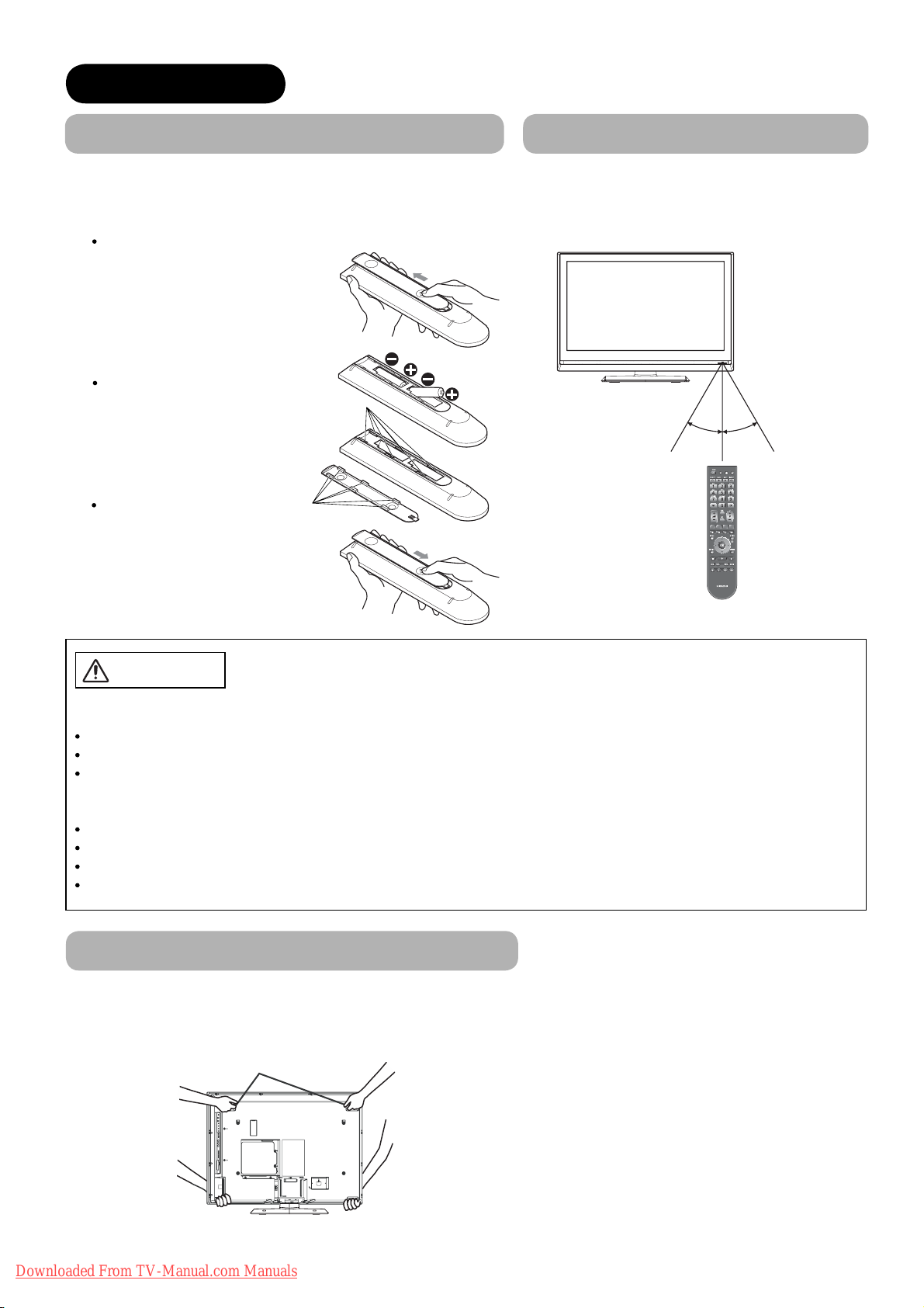
Remote Control Batteries Installation
This remote control operates on 2 “AA” batteries.
1.
Open the battery compartment cover
Slide open the battery compartment
cover on the backside in the
direction of an arrow, and remove
the cover.
2. Install the batteries
Install 2 “AA” batteries (included)
making sure the polarities match
the indication inside the
compartment.
3. Close the battery
compartment cover
Make sure of the positions
to fi t the projecting parts in
the holes, and slide the
compartment cover in the
direction of an arrow till it
clicks shut.
Holes
Projecting
parts
Handling the Remote Control
Use the remote control within about 5m from
front of the unit’s remote-control sensor and
within 30 degrees on both sides.
Within 30
degrees
About 3m About 3m
Within 30
degrees
Within
about 5m
CAUTION
It could cause corrosion or battery leakage and may result in physical injury
and/or property damage including fi re.
Never mix used and new batteries in the device.
Replace all the batteries in a device at the same time.
Remove the batteries if the remote control is not going to be used for an extended period of time.
To avoid possible failure, read the following instructions and handle the
remote control properly.
Do not drop or cause impact to the remote control.
Do not spill water or any liquid on the remote control.
Do not place the remote control on a wet object.
Do not place the remote control under the direct sunlight or near sources of excessive heat.
Caution When Moving the Main Unit
As this product is heavy, whenever it is moved, two people are required to transport it safely.
When transferring the unit, hold the unit by using the handgrips at the backside of the panel. (See the fi gure below for details.)
Handgrips
12
Downloaded From TV-Manual.com Manuals
PREPARATION (continued)
Safety Precaution on Main Unit Installation
Read SAFETY PRECAUTIONS (
4
to
7
) carefully besides this page.
*The Desktop Stand has been used for the illustration in this manual.
When installing the main unit, be sure to use the specifi ed mount units in order to obtain maximum performance
and maintain the safety.
We assume no responsibility or liability for personal injuries or property damages caused by use of other mount
units or improper installation.
As for the installation instruction, please read each user’s manual of the mount units: for Wall Mounting and
Ceiling Mounting.
In case of Wall or Ceiling Mounting, please ask your local dealer to arrange professional installation. Never
attempt to install it by yourself. It could cause injuries or damages.
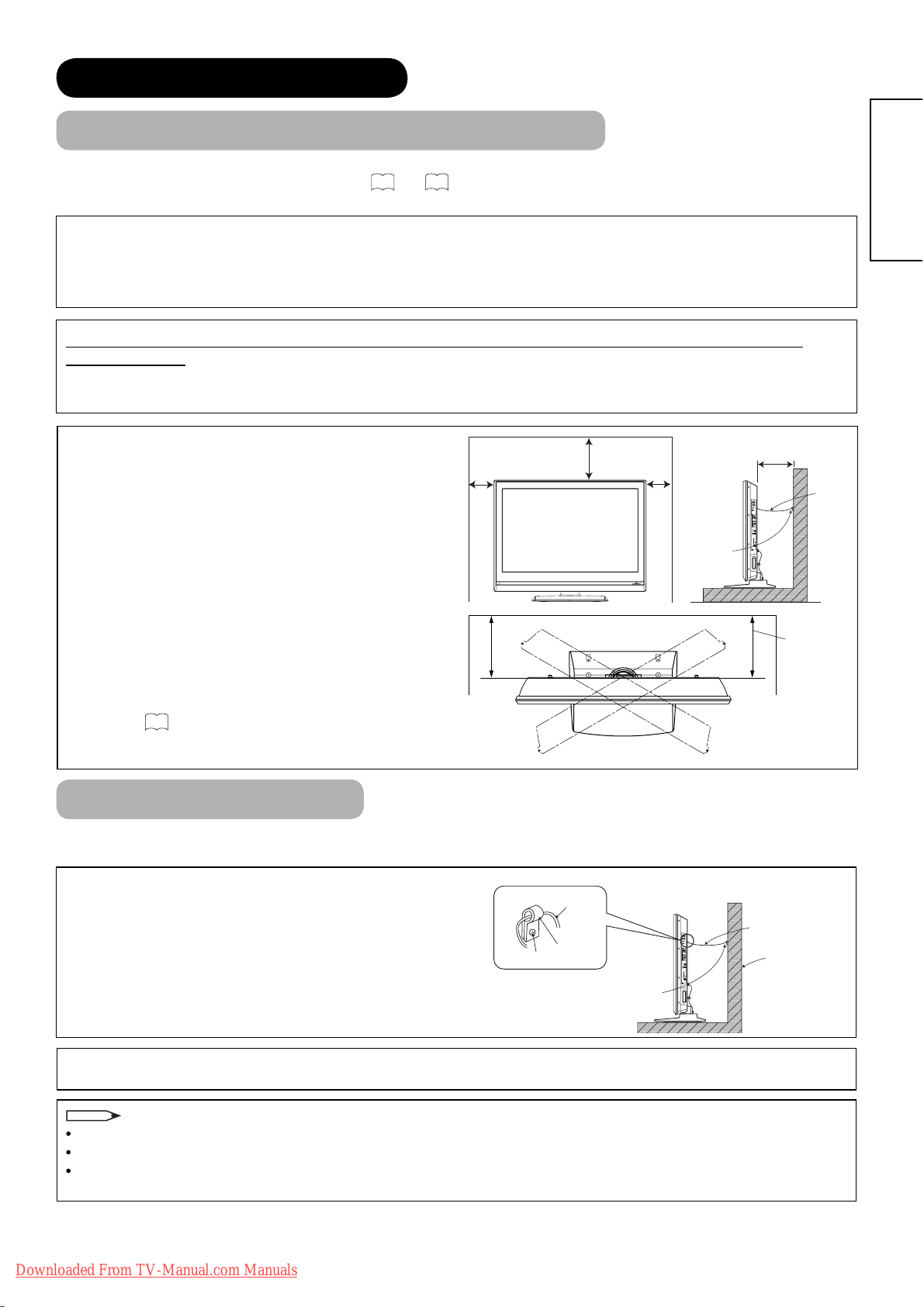
Please leave adequate space around this unit in order to
avoid increasing the internal temperature and keep safety
whilst using swivel function (if your TV has Swivel
10 cm
or more
30 cm or
more
10 cm
or more
10 cm or more*
function).
Make sure not to block any ventilation holes.
Do not install the unit in small space such as inside a
cabinet or the box.
Clamp
Leave more than 10cm of clearance from each side of
unit and 30cm from the top of unit to wall.
*1 Without Swivel function: Leave at least 10cm of
clearance behind rear unit.
*2 With Swivel function: Leave at least 25cm of clearance
25 cm or
more*
to obtain the maximum performance of Swivel
Function.
70
Refer to
for Swivel Function.
ENGLISH
1
Cord or
Chain
2
Anti-Tumble Measures
Install in a stable place and implement safety measure against overturning.
Securing to a wall or pillar
Using a commercially available cord, chain, and clamp,
secure the set to a wall or pillar.
Securing to ceiling
Using a commercially available cord, chain, and clamp, secure the set to a ceiling.
NOTE
For more information regarding the mounting of the unit, please contact your dealer.
Loosen a cord or chain enough whilst operating power swivel to avoid physical injury.
Please install the unit in a sensible location where it does not expose anyone to the danger of knocking into the
unit, causing injury to themselves or the LCD TV.
Cord or Chain
Hook
Screw
Cord or Chain
Wall or Pillar
Clamp
Downloaded From TV-Manual.com Manuals
13
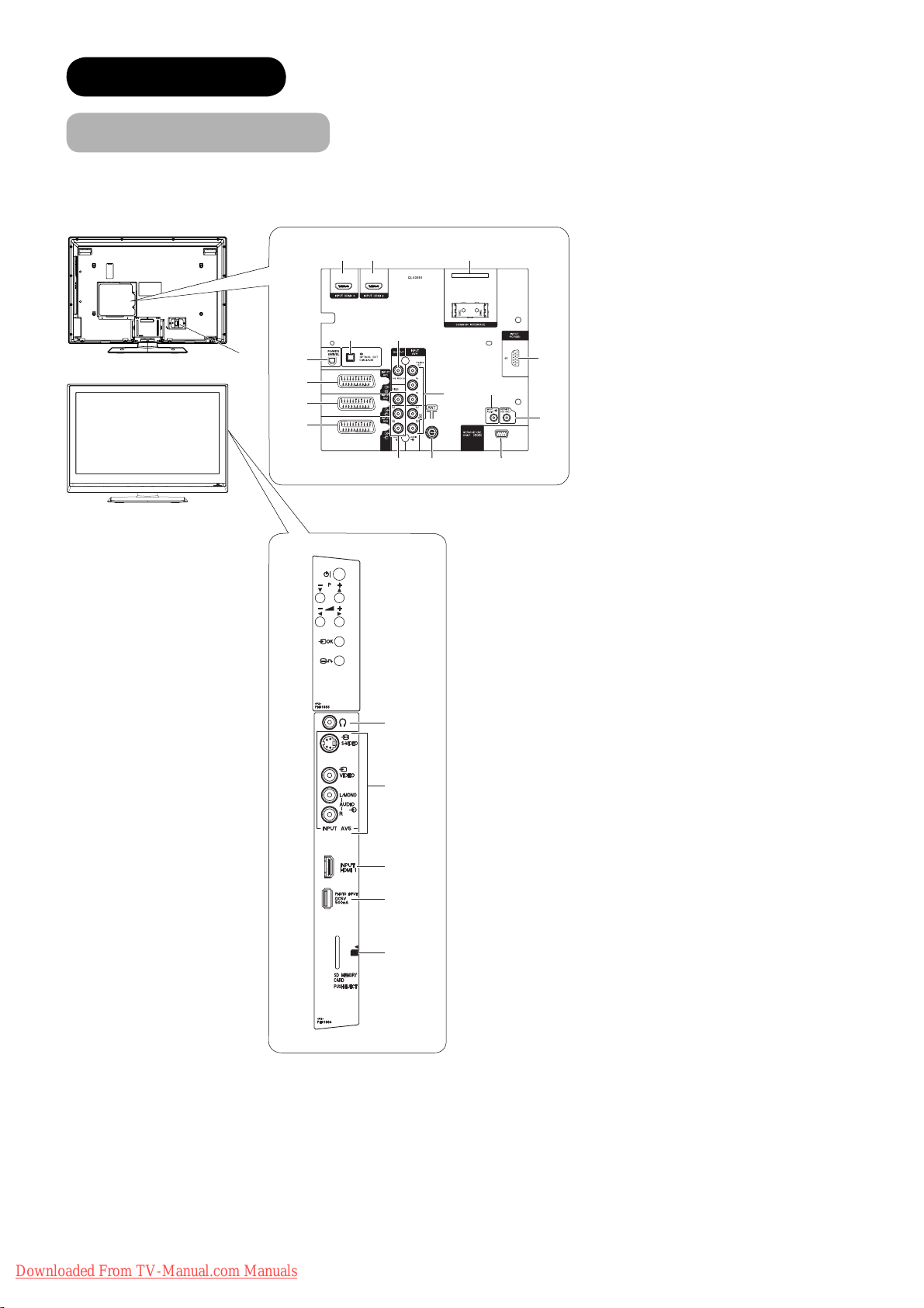
CONNECTION
827
Terminal Positions
1
0
3
4
5
#
@ $
! &
6
^
%
9
1 Power Cord Socket
2 Aerial Socket
3 AV1
4 AV2
5 AV3
6 AV4
7 Monitor Out
8 Service Use only
9 Service Use only
0 Power Swivel Terminal
! Optical Out (Digital Audio)
@ HDMI 2
# HDMI 3
$ Common interface slot
% PC Terminal
^ Mini stereo for Audio
& Sub Woofer
*
(
)
q
w
* Headphone terminal
( AV5
) HDMI 1
q Photo Input Terminal
w SD Memory Card slot
14
Downloaded From TV-Manual.com Manuals
CONNECTION (continued)
Connecting Procedure
This unit is ready for various kinds of connections. Make a connection in the following steps. Be sure to turn off the
Main Power fi rst when connecting external equipments.
1. Connect Power Cord to the rear panel.
2. Connect Aerial Lead.
3. Connect your external equipments to the unit if any.
4. Connect the Power Plug to the Wall Socket.
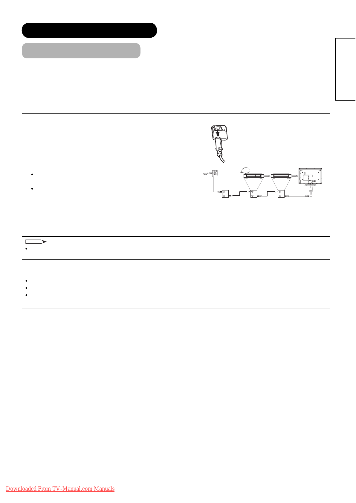
1. Connecting Power Cord to the Rear Panel
Connect Power Cord to the unit.
*Make sure not to connect the Power Plug to the Wall Socket
until all connections are completed.
2. Connecting Aerial Lead.
There are two ways to connect Aerial Lead.
When you do not have any other external equipment:
Connect the Aerial Lead directly into the Socket at rear panel.
When you have one or more external devices to connect:
1.
Use RF cable to connect between each equipment and aerial.
2. Connect the Aerial Lead to the Aerial Input socket of an
external device such as a VCR.
3. Connect the RF cable from the equipment ‘Out’ to the other equipment ‘In.’
4. Then, connect from the equipment ‘Out’ to “ANT” on the LCD screen Socket.
IN
OUT
STB VCR
IN
OUT
IN
OUT
[Example: Connecting aerial
through STB and VCR]
ENGLISH
NOTE
If analogue and digital broadcast signals are provided from separate aerials, please use a mixer and RF cable to
connect aerial socket in order to receive both signals.
Precautions when connecting the aerial
Please use a coaxial cable which is free from interference to connect the aerial.
Avoid using indoor aerial as this may be affected by interference. Please use outdoor aerial.
If noise appears in the picture, please use a double-shielded cable (not provided) for RF LEADS to reduce the
noise.
Downloaded From TV-Manual.com Manuals
15
CONNECTION (continued)
Connecting Procedure (continued)
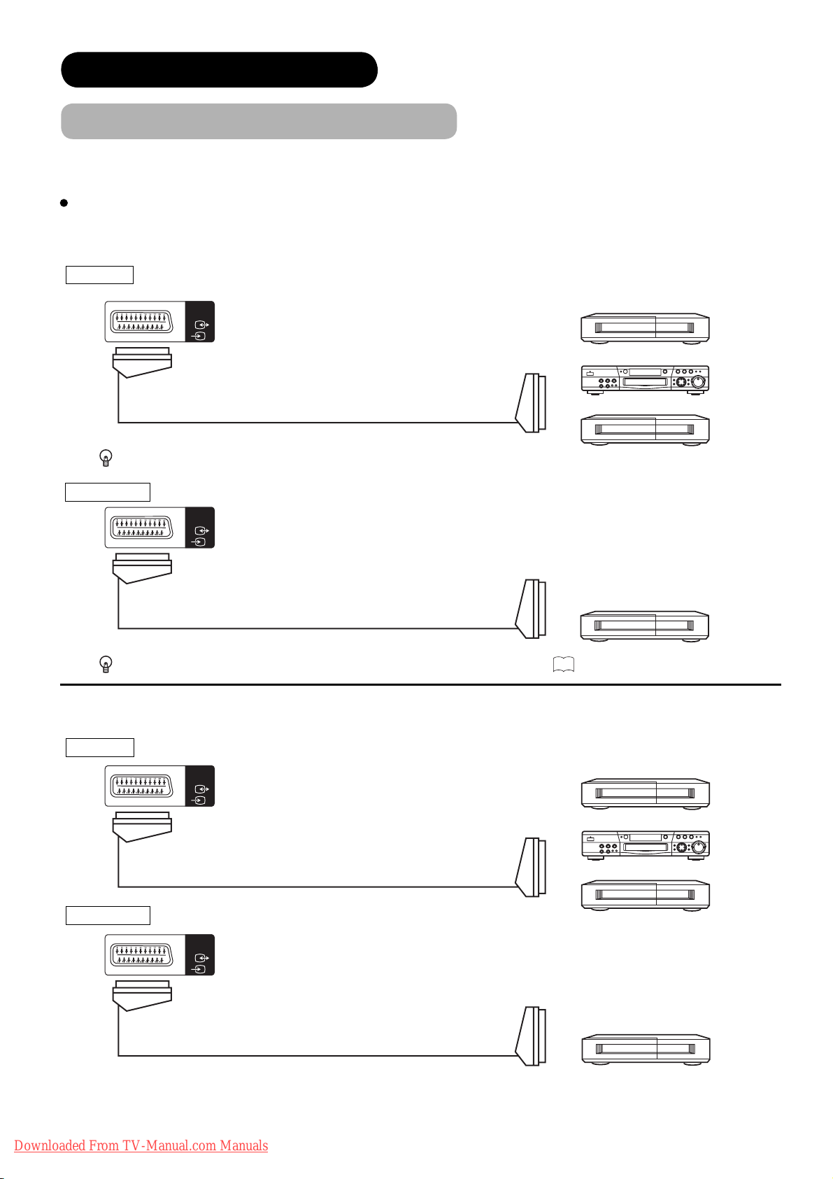
3. Connecting to External Equipment
Terminals on Rear
AV1 can be connected to the equipment with Composite/S-Video/Audio output, and Composite/Audio input.
The output signal
INPUT Composite/S-Video/Audio
can support not only Analogue but also Digital Terrestrial TV signals.
INPUT
AV1
[Example]
VCR
DVD player/recorder
IN OUT
Set-Top Box
If STB is connected to AV1 in France, it descrambles some of the Pay TV images by resending the signal again (In/Out).
OUTPUT Composite/Audio
INPUT
AV1
[Example]
VCR
(Recording Device)
OUT
IN
While View Timer is on, the active programme is output from AV1. See 53 for View Timer.
AV2 and 3 can be connected to the equipment with Composite/RGB/Audio output, and Composite/Audio input.
INPUT Composite/RGB/Audio
INPUT
AV2
[Example]
VCR
IN OUT
OUTPUT Composite/Audio
INPUT
AV2
OUT
16
Downloaded From TV-Manual.com Manuals
IN
DVD player/recorder
Set-Top Box
[Example]
VCR
(Recording Device)
CONNECTION (continued)
Connecting Procedure (continued)
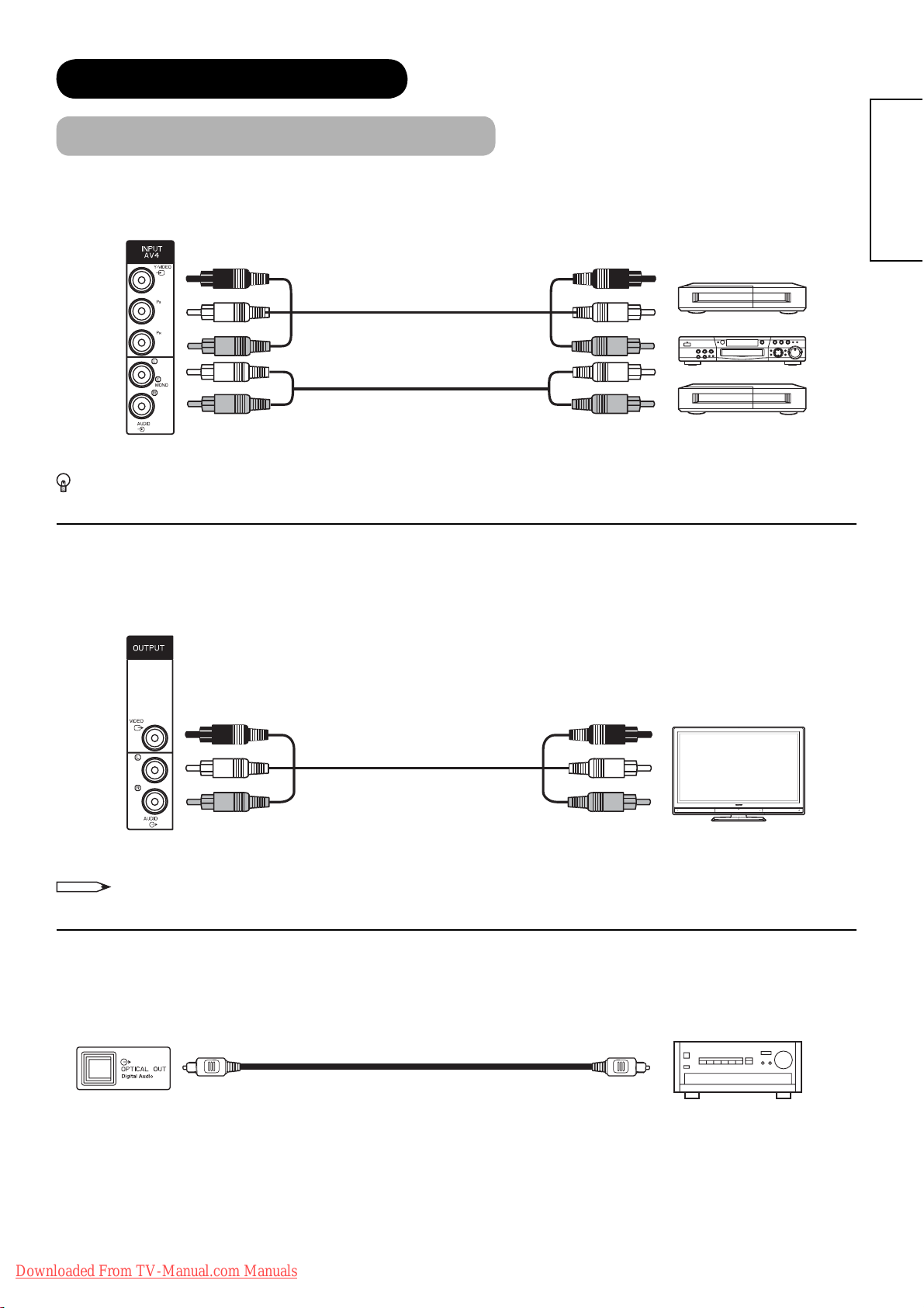
AV4 can be connected to the equipment with either Component or Composite output. When using as Composite, do
not insert the jacks into P
If your external device has a Component terminal, COMPONENT connection is recommended for higher quality
picture
.
or PR.
B
IN
OUT
[Example]
VCR
DVD player/recorder
Set-Top Box
ENGLISH
Monitor Out can be used to display same image as main unit on another monitor.
When this output terminal is connected to an external monitor with a 75 Ohm terminal, the same image from
composite (AV1~5), or RF signal can be displayed to the external monitor.
[Example]
Monitor
NOTE
OUT
IN
• Video output is not available from component or HDMI/RGB input.
®
Optical Out (Digital Audio) This provides Digital Audio Output for your audio device that is Dolby
Digital and PCM
compatible, such as an audio amplifi er.
OUT IN
Downloaded From TV-Manual.com Manuals
[Example]
Stereo System Amplifi er
17
CONNECTION (continued)
Connecting Procedure (continued)
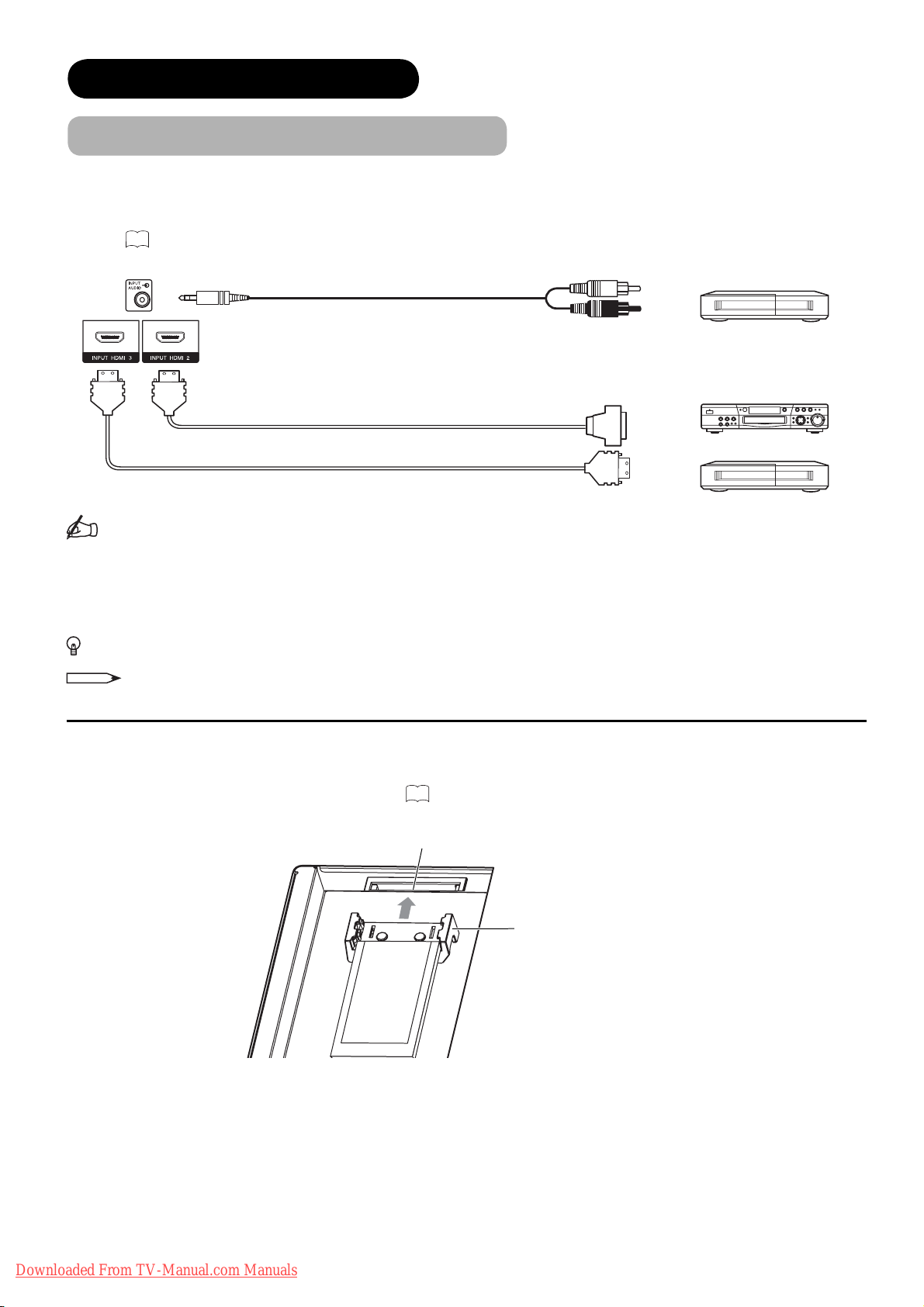
HDMI 2 and 3
terminal can be connected to the devices with HDMI output. If the external device has DVI output, this can
be available with HDMI-DVI cable. In case of using the HDMI-DVI cable, connect to audio terminal besides HDMI input
terminal.
Refer to 20 about HDMI1 terminal on side.
[Example]
VCR
DVD player/recorder
Set-Top Box
(HDMI)
IN
(Mini Stereo plug)
(HDMI)
or
OUT
(DVI)
(HDMI)
Information
HDMI (High Defi nition Multimedia Interface) is next-generation multimedia I/O interface. Only one cable is used to
transmit all video/audio/control signals, which creates easy connection.
Moreover, those digital signals can produce high quality data without any degradation.
You are provided with three HDMI terminals on side and rear.
If your external device has a HDMI terminal, HDMI connection is recommended for higher quality picture and sound.
NOTE
When the signal format is 1080p, use a cable of less than 5 metres.
Common Interface Slot
allows you to receive Pay TV service with detachable modules.
Before inserting the module, make sure to turn off the main power. And then insert the module through the clamp all the way
into the slot. Make sure to insert it correctly. Refer to
Common Interface Slot
Common Interface Module
45
for the details.
Clamp
18
Downloaded From TV-Manual.com Manuals
CONNECTION (continued)
Connecting Procedure (continued)
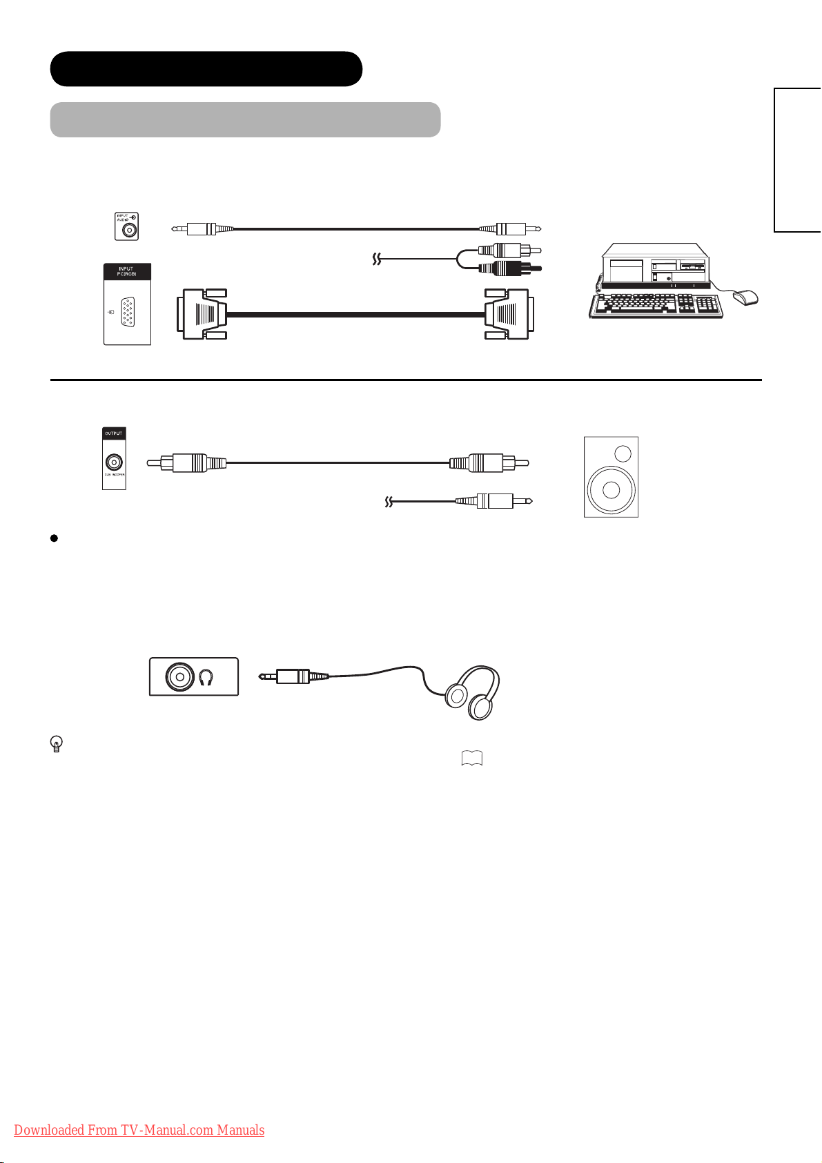
PC terminal (D-sub 15 pin) is connected to PC, which allows Analogue RGB signal. Connect to also audio terminal
on the rear besides PC (RGB) terminal.
IN OUT
[Example]
(Mini Stereo plug)
Sub Woofer terminal can bring the deep bass sound from the external speaker equipped with a built-in amplifi er.
or
ENGLISH
OUT
IN
or
[Example]
Terminals on Side
Since the following terminals are located on the side, it is very convenient to connect an extra device on a temporary
basis after completing the connections on the rear panel.
Headphone
(Mini Stereo plug)
In case of setting “Headphone Select” in Audio Menu to “H.Phone only”, the audio from the speaker will be
muted when connecting the headphone to this terminal. Refer to
42
.
Downloaded From TV-Manual.com Manuals
19
CONNECTION (continued)
Connecting Procedure (continued)
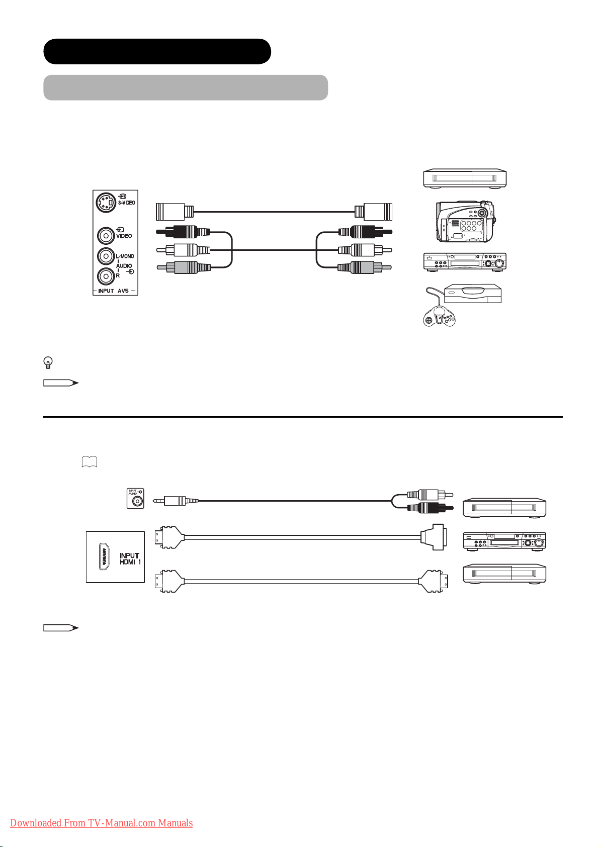
AV5 can be connected to the equipment with S-video output and composite output.
[Example]
VCR
IN
OUT
Camcorder
DVD player/recorder
Home video game system
If your external device has S-video terminal, S-VIDEO connection is recommended for higher quality picture.
NOTE
If both S-video and video input terminals of AV5 are connected at the same time, S-video will have its priority.
HDMI 1
with HDMI-DVI cable. In case of using the HDMI-DVI cable, connect to audio terminal on the rear besides HDM
Refer to
terminal can be connected to the devices with HDMI output. If the external device has DVI output, this can be available
I
18
for details about HDMI2 and HDMI3 terminal on the rear.
IN OUT
input terminal.
[Example]
VCR
(Mini Stereo plug)
(HDMI)
(HDMI)
NOTE
or
When the signal format is 1080p, use a cable of less than 5 metres.
(DVI)
(HDMI)
DVD player/recorder
Set-Top Box
20
Downloaded From TV-Manual.com Manuals
CONNECTION (continued)
Connecting Procedure (continued)
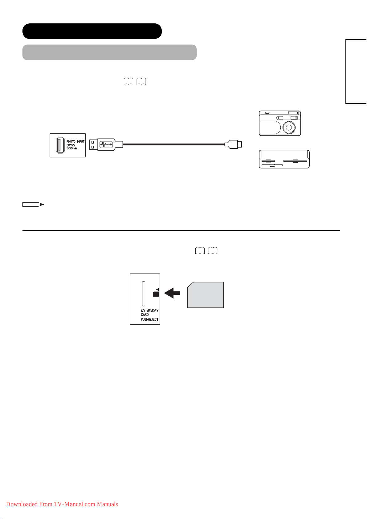
Photo Input terminal can be connected to a digital still camera or USB card reader with USB cable. For details, refer
to the Photo Input function shown on
IN
NOTE
65~69
This photo input terminal does not support general USB devices such as USB memory.
Please do not connect with those devices.
.
[Example]
Digital Camera
USB Card reader
OUT
ENGLISH
SD Memory Card slot can be used for the Photo Input function with the SD (or MMC) card memory containing
pictures. For details, refer to the Photo Input function shown on
65~69
SD Card / MMC
.
Downloaded From TV-Manual.com Manuals
21
CONNECTION (continued)
Connecting Procedure (continued)
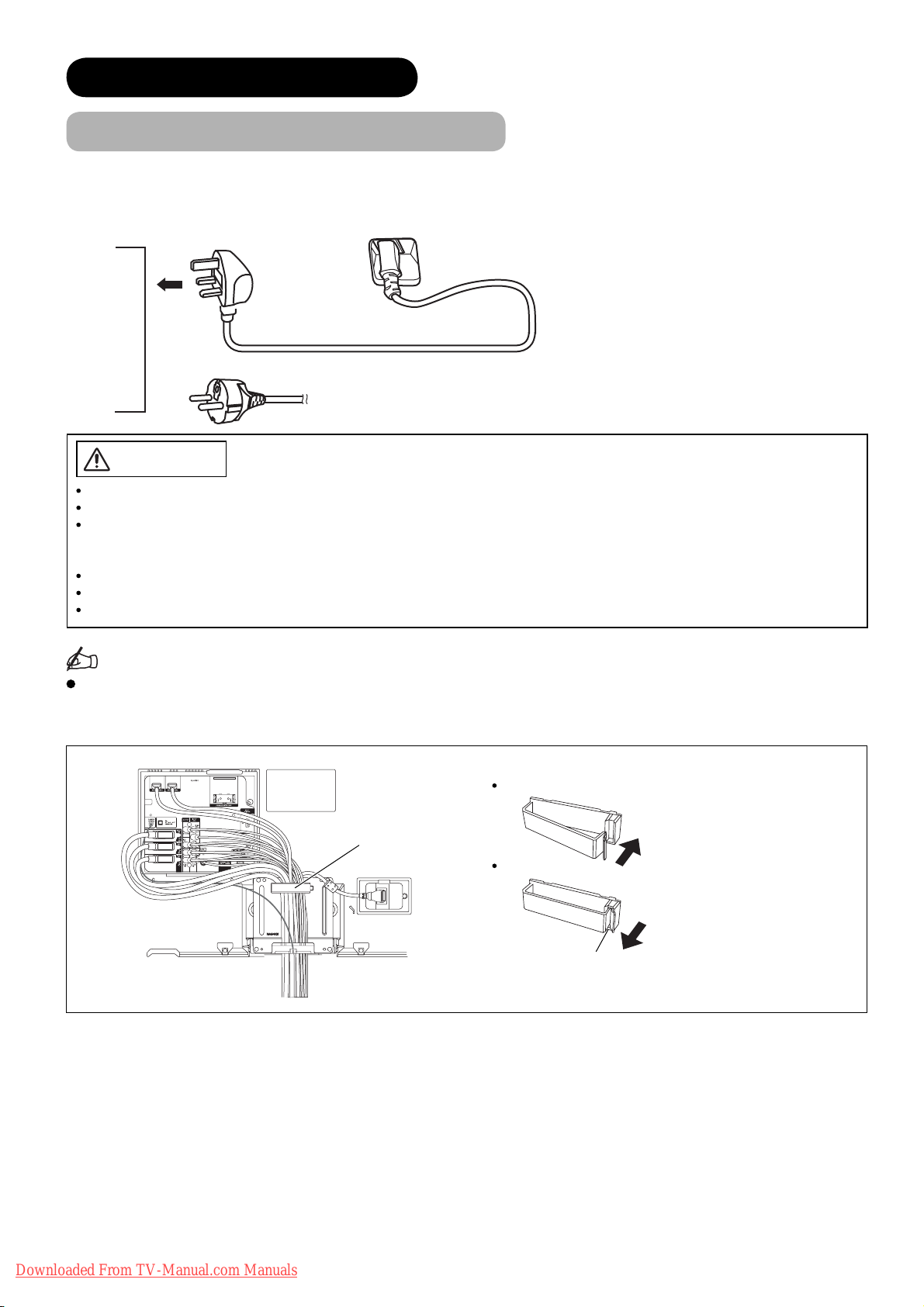
4. Connecting the plug into the wall socket
Connect the Power Cord after completing all other connections.
(The type of plug is different from this drawing for some countries.)
UK only
Except UK
CAUTION
Use only the Power Cord provided.
Do not use a power supply voltage other than that indicated (AC220-240V, 50Hz). It may cause fi re or electric shock.
For the LCD television, a three-core power cord with a ground terminal is used for effi ciency protection. Always be sure
to connect the
source converter plug, use an outlet with a ground terminal and screw down the ground line.
Connection to a Cable Distribution System is to be provided through a galvanic isolator.
Ensure that both ends of power cord are easily accessible.
If you have to change the power cord, please use the certifi ed power cord that meets your region’s safety standard.
Power Cord
to a grounded outlet and make sure that the cord is properly grounded. If you use a power
Information
How to secure the cables.
After connecting all of the cables to the terminals, secure them with the clamps.
When you secure the cables, please be careful not to tighten too much.
How to secure the clamp:
To set
Clamp
To unfasten
Knob
Push the clump in the
direction of the arrow until
it clicks.
Whilst pushing the knob,
pull it in the direction of the
arrow.
22
Downloaded From TV-Manual.com Manuals

BASIC OPERATION
Power On/Off
Now, turn On the main power to the unit. Make sure that the power cord is
plugged into the wall socket.
To turn On the power of the unit:
1. Press the Main Power switch on the unit.
The Indicating Lamp will illuminates in Red (Standby mode).
2. Press Sub Power button either on the control panel or on the remote control.
• The colour of the Indicating Lamp turns into Blue, and the image will be
displayed on the screen.
To turn Off the power of the unit:
1. Press Sub Power button either on the control panel or on the remote control.
• The image disappears from the screen and the Indicating Lamp turns into
Red (Standby mode).
Main Power switch
ENGLISH
(located on the bottom
surface)
Sub Power
button
2. Press Main Power switch to completely turn Off the power of the unit.
Sub Power button
The Indicating Lamp Status Check
Indicating Lamp
Status
Off Off Main power ĺ Off —
Red Standby mode
*1
Blue
Pulsing Blue Power Save mode
Orange
*3
Green ——
*1 After turning on, the indicating lamp pulses for an instant and then starts lighting. Also, the indicating lamp blinks
whilst using remote control.
In case you do not want it to pulse/blink, select “Off” in “LED Mode” from Confi guration menu. Refer to
the details.
*2 About Power Save mode, see “Power Save Mode” and “When Following Messages Appear on the Screen” on
and74 for details.
*3 The indicating lamp blinks in orange if the View Timer setting does not have time information.
Power Status Power Switch Status View Timer Status
Main power ĺ On
Sub power ĺ Off
On
*2
Main power ĺ On
Sub power ĺ On
Main power ĺ On
Sub power ĺ On
——
Whilst TV has View Timer
set up.
—
—
—
Whilst operating a
programme which has set
up View Timer.
34
for
72
NOTE
• If the image does not appear on the screen at all, or have any problem, see TROUBLESHOOTING on74 ~76.
It may help you to solve the problems.
• After turning On, it takes several tens of seconds until TV starts up. If selecting “On” in “Quick Start Options” from
Confi guration menu, you can shorten the processing time. Refer to
34
.
• You can turn On the power only by pressing the Sub Power button during Standby mode.
• Do not switch the power On/Off repeatedly in a short period of time. It could cause malfunction.
• If the power outage occurs whilst using the unit, turn Off the Main Power switch before you leave to avoid sudden
power surges when power comes back.
Downloaded From TV-Manual.com Manuals
23
BASIC OPERATION (continued)
Easy Setup
When you turn ON the TV for the fi rst time, your TV automatically leads
to the settings of “Language,” “Target,” and “Country (TV and DTT).”
(Also, refer to the attached Quick Guide.)
The integrated DVB-T tuner will only receive MPEG2 compressed
signals. Thus, it will not work with MPEG4 signals.
Hitachi can't guarantee the functionality of the integrated DVB-T
tuner in case of a change of the DVB-T standard.
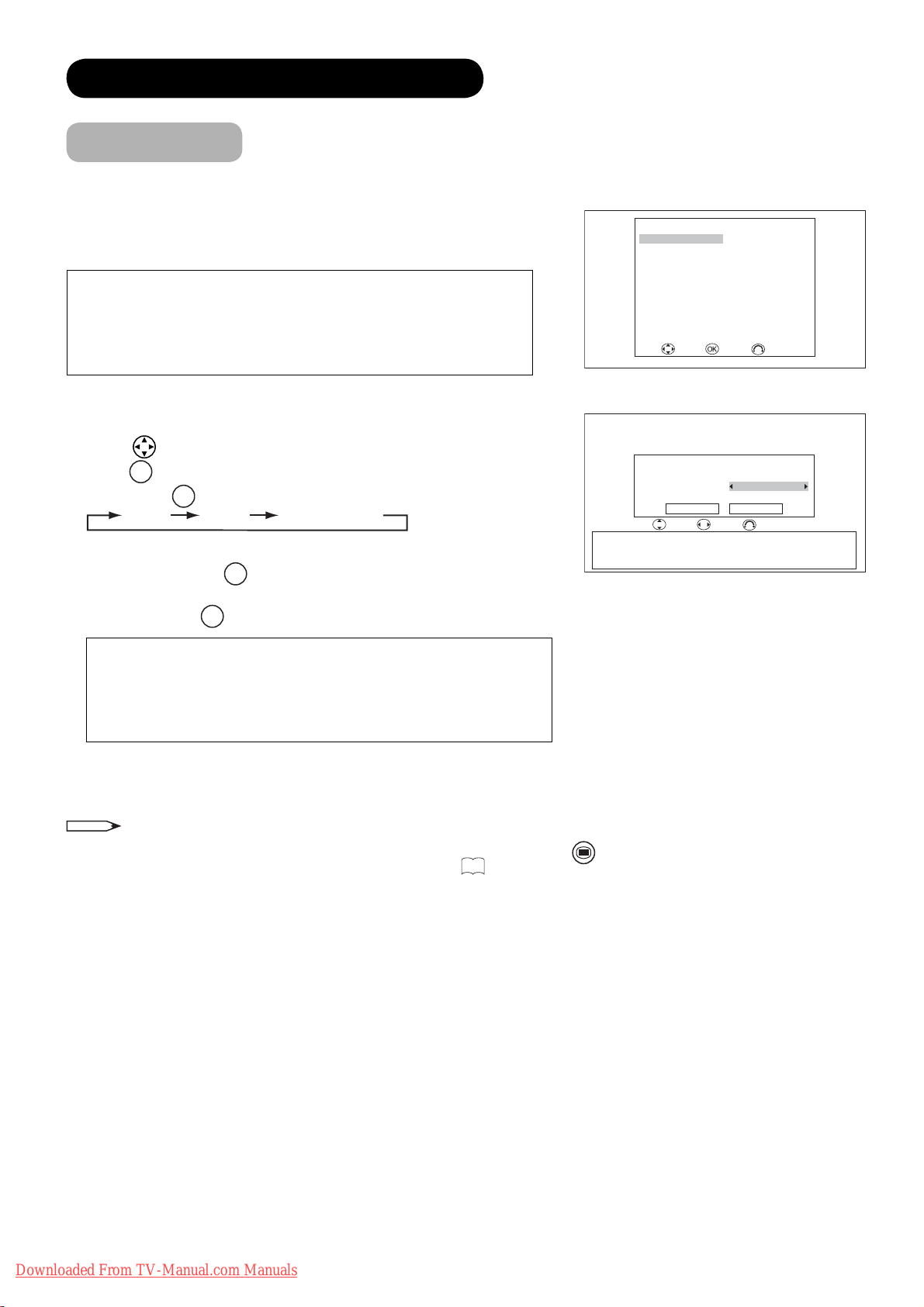
1.
The fi rst screen appeared will ask you to choose the language of your
TV’s
display.
2. Using
press
3. Then, using
4. If you choose “TV” or “TV&DTT” in “Target,” select the country for
analogue scan with
5. If you choose “DTT” or “TV&DTT” in “Target,” select the country for
digital scan with
button, select language you preferred from the list and
OK
button.
◄►
button, select the target for auto scan.
TV DTT TV&DTT
◄►
button.
◄►
button.
English Svenska
Français Norsk
Deutsch Suomi
Italiano Dansk
Español
Nederlands
Ελληνικά
Türkçe Slovensko
Português Hrvatski
Română
Target TV&DTT
TV Country United Kingdom
DTT Country United Kingdom
Austria / Belgium / Croatia / Czech Republic / Denmark / Finland / France
Germany / Greece / Hungary / Iceland / Ireland / Italy / Luxembourg
Netherlands / Norway / Poland / Portugal / San Marino / Slovakia / Slovenia
Spain / Sweden / Switzerland / Turkey / United Kingdom / Ukraine
Easy Setup
Magyar
Select Enter Cancel
Continue Cancel
Select Adjust Cancel
Česky
polski
Easy Setup
<Example: L37X01U>
For L37X01U model:
Please note that the country of digital scan is automatically set as
“United Kingdom,” which is shown as grey (unavailable to select
the other countries).
6. The auto tuning screen appears, and your TV will now search
channels through the frequencies storing them in order.
NOTE
• If you want to change the setting after completing this easy setup, press
“Initial Setup” menu in order to set up individually. (See
31
.)
MENU
button and select “Easy Setup” from
24
Downloaded From TV-Manual.com Manuals
BASIC OPERATION (continued)
Channel Selections
There are 4 ways to select the channels: stepping through the channel, selecting by number, selecting from the
on-screen channel list, and using the Electronic Programme Guide (EPG).
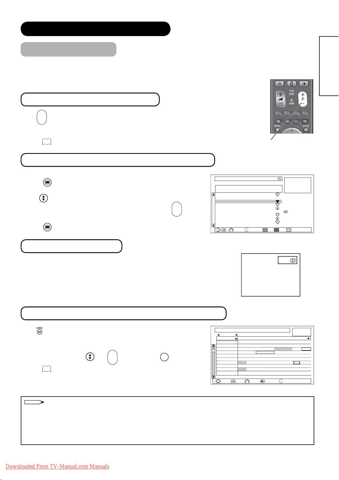
Stepping through the Channel
+
P
-
Press
button on the remote control or Channel Up/Down button on the
control panel to switch the next or previous channel on the list. Information
banner is displayed every time channel is switched.
55
Refer to
about the information banner.
Channel Up/Down button
Selecting from the On-screen Channel List
ENGLISH
MENU
1. Press
Select “Channel Manager” from Main Menu to show channel list.
2.
button on the remote control.
3. Use button to move through the list. A picture of the selected
+
P
channel is displayed in the upper right of the screen. Use
to move to the next or the previous page.
4. Press
MENU
button again to watch the channel selected latest in 3.
button
-
Channel Manager Wed 30 Jan 2008
TV
FRANCE
# Ch Name Status
1 048MHz Music
2 055MHz BG010
3 175MHz ATVCh
4 211MHz GTTCh
5 C21 VVCh3
6 511MHz HitTV
7 543MHz uTV2
8 623MHz News2
9 C22 News3
10 C23 Sport
<Example: L37X01E in TV mode>
Selecting by Number
Enter the number based on its channel list by the numeric buttons on the remote
control. Skip channels can be selected, too. A small box appears in the upper right
corner of the screen to show entered number. Channel is switched along with the
information banner. If the entered number is not valid for one of the setup
channels, it automatically selects the closest channel.
Using the Electronic Programme Guide (EPG)
Press button or select “Guide” in Function menu to access EPG screen.
The EPG screen displays a list of the stored channels (10 channels per
page) along with the description of the programme being broadcast.
+
P
To change channels, use
Refer to
52
regarding Electronic Programme Guide for details.
and
button and then OK button.
-
Guide Wed 30 Jan 2008 9:00
Sat 02 Feb Category: All Channels
Channel 9:00 9:30 10:00 10:30
801 DTT-1 Natural Life Creative Live
802 DTT-ch10
3 DTT-ch03 Breakfast Time News+30 min news Cool 01 G12
116 DTT-ch06 Cool 00 Cool 01 One hour Morning Show
208 DTT-ch03 Sunrize Information A. B Smith Car Detector
10 Cinema Normal T Morning Movie Sea
20 Super20 Reset Morning Song Ball ABCDEF
30 Trains30 Trafic Information Headine News Shopping 00
40 News360 Headine News 15++ Big Game
50 Sports-5 15min Info. Yesterday Game Wide Electronics
Sat 02 Feb 8:00 - 8:30 1003 DTT-ch03 30min News
Select Enter Function
+
Return
P
Page
–
Del. Skip Sort
123
<Example: DTT mode>
[DTT mode only]
Morning News
Morning News+ Small Town
+
P
Return
Page
–
<Example: Matrix View>
Hide
Fine Tuning
Single Scan
Full Scan
Scan Setting
Morning News
+
NOTE
Please note that DTT menu and image from MHEG Digital Teletext (without picture) cannot be supported at the
same time. (Audio and picture are available.)
The followings are the examples.
•
If the quarter images on EPG or Channel List screen is from MHEG Digital Teletext, those images cannot be displayed.
• If you try to display the menu whilst displaying MHEG Digital Teletext (without picture), the teletext screen
becomes unavailable.
Downloaded From TV-Manual.com Manuals
25
BASIC OPERATION (continued)
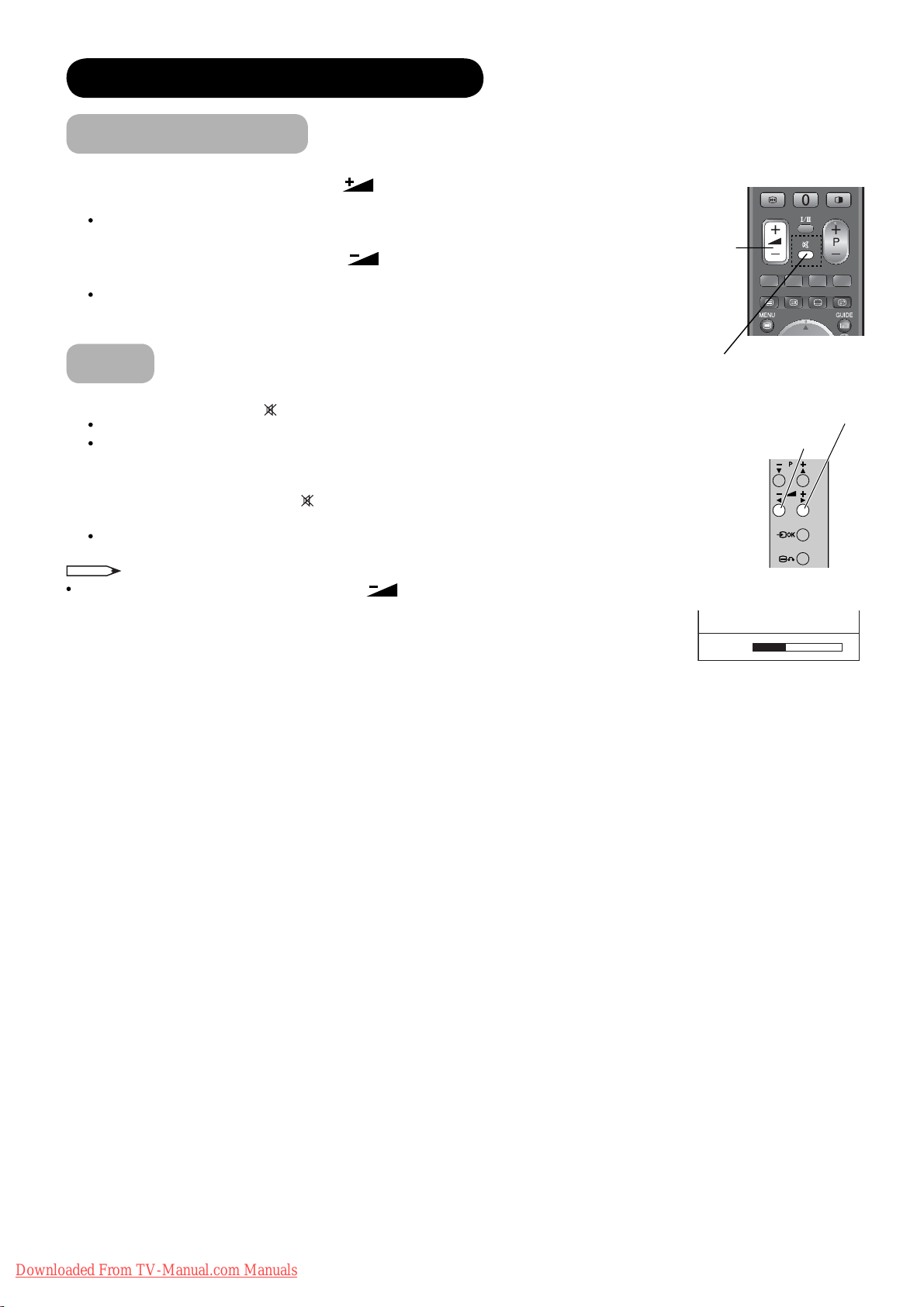
Volume Up/Down
1. To increase the sound volume, press button on the remote control,
or Volume Up button on the control panel.
The Volume Indicator value on the screen will shift right.
2. To decrease the sound volume, press
remote control or Volume Down button on the control panel.
The Volume Indicator value on the screen will shift left.
button on the
Volume Up/Down
button
Mute
1. To mute the sound, press button on the remote control.
The sound of the unit is temporarily turned Off.
The colour of the Volume Indicator will turn into grey
whilst muting the volume.
2. To bring the sound back, press
either remote control or the control panel.
The colour of the Volume Indicator will turn back to white.
NOTE
You can decrease the volume by pressing button
whilst the sound is muted.
button again, or Volume Up button on
Mute button
Volume Up button
Volume Down button
Volume 13
Volume Indicator
26
Downloaded From TV-Manual.com Manuals

BASIC OPERATION (continued)
Input Switching to DTT/TV/AV1~5/HDMI1~3/RGB
There are several ways to change the input mode as mentioned below.
Please select your preferred way.
z You can select DTT and TV mode directly.
Press button on the remote control. Each time the button is pressed,
the mode is switched between DTT and TV mode.
z Display Input Switching Banner to select the input mode.
1. Press
button on the remote control or Input Select button on
the control panel to display Input Switching Banner.
2. Select the input mode.
Each time button on the remote control or Input Select button
on the control panel is pressed, the screen displays the
corresponding mode by following order.
DTT
RGB
Also, you can change the input mode back and forth by using
AV1 AV2 AV3TV
HDMI 2HDMI 3
HDMI 1 AV5
AV4
◄►
button on the remote control or Volume Up/Down button on the
control panel.
z Input Mode buttons (AV1~AV5, HDMI 1~3 and RGB mode)
After pressing
button, press the desired Input Mode button on the
remote control.
Input
AV
AV1
Composite
AV1
Input Select button
Input Mode
button
ENGLISH
Volume Down button
Volume Up button
Input Select button
Downloaded From TV-Manual.com Manuals
27
BASIC OPERATION (continued)
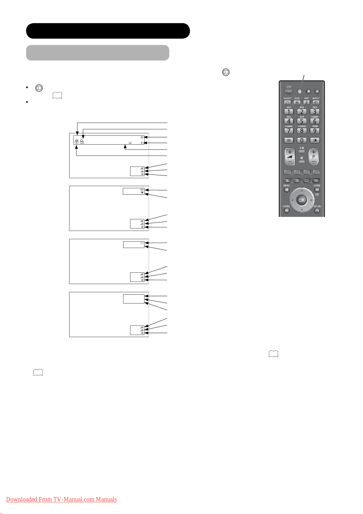
Input Signal Screen Display
The input signal status can be displayed on the screen by pressing the
the remote control.
+
button is pressed again in DTT mode, it can show the information banner.
If
Refer to
55
about the information banner.
The display will go out in approximately 6 seconds.
Channel name
Rating age (if broadcasted)
DTT
ABTV
12
10
English Spanish
Channel number
Audio language
*1
Subtitle language (DVB)
Channel lock (if selected)
Off-timer
On-timer
Current time
*2
Channel name and TV position
TV
30min.
01h 59m
17:45
ABTV 1
Audio A2/NICAM mode
Off-timer
VIDEO
30min.
01h 59m
17:45
AV1
Component
AV
On-timer
Current time
Input mode
*2
Signal mode
+
button
*1
of
Recall button
Off-timer
On-timer
Current time
*2
Input mode
Input horizontal frequency
RGB
30min.
01h 59m
17:45
H: 48.4kHz
V: 60.1 Hz
RGB
Input vertical frequency
Off-timer
30min.
01h 59m
17:45
On-timer
Current time
*2
*1 If the programme provides special audio/subtitle (DVB) service, icons may appear. See55 for details.
*2 If time signal is received from DTT broadcasting or the time is set in “Timers”, the current time is displayed. See
44
for details.
28
Downloaded From TV-Manual.com Manuals
 Loading...