


|
|
|
|
|
|
|
|
|
|
|
|
|
|
Model |
|
P 13F |
|
Planer |
||
Modele |
|
|
Raboteuse |
|||
Modelo |
|
|
|
Cepilladora |
||
|
|
|
|
|
|
|
|
|
|
|
|
|
|
INSTRUCTION MANUAL AND SAFETY INSTRUCTIONS
 WARNING
Improper and unsafe use of this power tool can result in death or serious bodily injury!
This manual contains important information about product safety. Please read and understand this manual before operating the power tool. Please keep this manual available for others before they use the power tool.
MODE D'EMPLOI ET INSTRUCTIONS DE SECURITE
 AVERTISSEMENT
Une utilisation incorrecte et dangereuse de cet outil motorisé peut entraîner la mort ou de sérieuses blessures corporelles!
Ce mode d’emploi contient d’importantes informations à propos de la sécurité de ce produit. Prière de lire et d’assimiler ce mode d’emploi avant d’utiliser l’outil motorisé. Garder ce mode d’emploi à la disponibilité des autres utilisateurs avant qu’ils utilisent I'outil motorisé.
MANUAL DE INSTRUCCIONES E INSTRUCCIONES DE SEGURIDAD
 ADVERTENCIA
¡La utilización inapropiada e insegura de esta herramienta eléctrica puede resultar en lesiones serias o en la muerte!
Este manual contiene información importante sobre la seguridad del producto. Lea y comprenda este manual antes de utiIizar la herramienta eléctrica. Guarde este manual para que puedan leerlo otras personas antes de que utilicen la herramienta eléctrica.

TABLE OF CONTENTS
English
SECTION |
PAGE |
SECTION |
PAGE |
Technical Data ......................................................................... |
3 |
General safety rules ................................................................ |
4 |
Specific Safety instructions for the planer ............................ |
5 |
Electrical information ............................................................. |
7 |
Know your planer .................................................................... |
8 |
Assembly and adjustments ................................................... |
9 |
Operations ............................................................................. |
13 |
Maintenance .......................................................................... |
16 |
Troubleshooting guide ......................................................... |
17 |
Parts list ................................................................................. |
48 |
HITACHI AUTHORIZED SERVICE CENTERS
Service under this warranty is available from Hitachi Koki U.S.A., Ltd. at :
IN THE U.S.A. |
IN CANADA |
3950 Steve Reynolds Blvd. Norcross, GA 30093
9409 Owensmouth Ave. Chatsworth, CA 91311
OR CALL: (800) 546-1666 for a service center nearest you.
6395 Kestrel Road Mississauga, ON L5T 1Z5
OR CALL: (800) 970-2299 for a service center nearest you.
TABLE DE MATIERES
Français
SECTION |
PAGE |
SECTION |
PAGE |
Spécifications techniques ..................................................... |
18 |
Consignes de sécurité ........................................................... |
19 |
Consignes de sécurité spécifiques à la raboteuse ............. |
20 |
Informations relatives à l'électricité .................................... |
22 |
Connaître votre raboteuse .................................................... |
23 |
Montage et réglages ............................................................. |
24 |
Opération ............................................................................... |
28 |
Entretien ................................................................................. |
31 |
Guide de dépannage ............................................................. |
32 |
Liste des pièces ..................................................................... |
48 |
CENTRES TECHNIQUES HITACHI AGREES
La réparation est réalisée dans le cadre de cette garantie par Hitachi Koki U.S.A., Ltd. :
AUX ETATS-UNIS
3950 Steve Reynolds Blvd. Norcross, GA 30093
9409 Owensmouth Ave. Chatsworth, CA 91311
OU APPELEZ LE : (800) 546-1666 pour connaître le centre technique le plus proche de chez vous.
AU CANADA
6395 Kestrel Road Mississauga, ON L5T 1Z5
OU APPELEZ LE : (800) 970-2299 pour connaître le centre technique le plus proche de chez vous.
ÍNDICE
Español
SECCIÓN |
PÁGINA |
SECCIÓN |
PÁGINA |
Datos técnicos ....................................................................... |
33 |
Normas de seguridad generales .......................................... |
34 |
Instrucciones De Seguridad Específicas Para La Cepilladora .... |
35 |
Información eléctrica ............................................................ |
37 |
Conozca su cepilladora ......................................................... |
38 |
Montaje y ajustes .................................................................. |
39 |
Funcionamiento .................................................................... |
43 |
Mantenimiento ...................................................................... |
46 |
Guía de solución de problemas ........................................... |
47 |
Lista de piezas ....................................................................... |
48 |
CENTROS DE SERVICIO AUTORIZADOS DE HITACHI
Hitachi Koki U.S.A. Ltd. proporciona un servicio de reparaciones bajo esta garantía en:
EN EE.UU.
3950 Steve Reynolds Blvd. Norcross, GA 30093
9409 Owensmouth Ave. Chatsworth, CA 91311
O LLAME AL: (800) 546-1666 para informarse del centro de reparaciones más cercano.
EN CANADA
6395 Kestrel Road Mississauga, ON L5T 1Z5
O LLAME AL: (800) 970-2299 para informarse del centro de reparaciones más cercano.
— 2 —

English
 WARNING
Some dust created by power sanding, sawing, grinding, drilling and other construction activities contains chemicals known to the state of California to cause cancer, birth defects or other reproductive harm. Some examples of these chemicals are:
•Lead from lead-based paints
•Crystalline silica from bricks, cement and other masonry products
•Arsenic and chromium from chemically treated lumber
Your risk from these exposures varies, depending on how often you do this type of work. To reduce your exposure to these chemicals, work in a well-ventilated area and work with approved safety equipment such as dust masks that are specially designed to filter out microscopic particles.
|
TECHNICAL DATA |
|
|
|
|
13” PLANER |
|
|
Motor |
|
15A, 120V, 60Hz |
|
|
|
Maximum stock width |
|
13” |
|
|
|
Thickness of cut |
|
Min. 1/8” |
|
|
|
Maximum depth of cut |
|
3/32” |
|
|
|
Feed speed |
|
24.08 ft/min |
|
|
|
Number of blade |
|
2 |
|
|
|
RPM (no load) |
|
8000 min-1 |
Weight |
|
101.4 lb (46 kg) |
|
|
|
— 3 —

English
GENERAL SAFTY RULES
Safety is a combination of common sense, staying alert and knowing how your planer works.
 WARNING
TO AVOID MISTAKES THAT COULD CAUSE SERIOUS INJURY, DO NOT PLUG IN THE PLANER UNTIL THE FOLLOWING STEPS HAVE BEEN READ AND UNDERSTOOD.
1.READ and become familiar with this entire instruction manual. LEARN the tool’s applications, limitations, and possible hazards.
2.AVOID DANGEROUS CONDITIONS. DO NOT use power tools in wet or damp areas or expose them to rain. Keep work areas well-lit.
3.DO NOT use power tools in the presence of flammable liquids or gases.
4.ALWAYS keep your work area clean, uncluttered, and well-lit. DO NOT wok on floor surfaces that are slippery with sawdust or wax.
5.KEEP BYSTANDERS AT A SAFE DISTANCE FROM the work area, especially when the tool is operating. NEVER allow children near the tool.
6.DO NOT FORCE THE TOOL to do a job for which it was not designed.
7.DRESS FOR SAFETY. DO NOT wear loose clothing, gloves, neckties, or jewellery (rings, watches) when operating the tool. They can get caught and draw you into moving parts. ALWAYS wear non-slip footwear, and tie back long hair.
8.WEAR A FACE MASK OR DUST MASK. Tool operation produces dust.
9.ALWAYS remove the power cord plug from the electrical source when making adjustments, changing parts, cleaning or working on the tool.
10.KEEP GUARDS IN PLACE AND IN WORKING ORDER.
11.ADOID ACCIDENTAL START-UPS. Make sure the power switch is in the OFF position before plugging in the power cord.
12.REMOVE ADJUSTING TOOLS. ALWAYS MAKE SURE all tools are removed from the planer before turning it on.
13.NEVER LEAVE TOOL ON WHILE UNATTENDED. Turn the power switch to OFF. DO NOT leave the tool until it has come to a complete stop.
14.NEVER STAND ON THE TOOL. Serious injury could result if the tool tips or is accidentally hit. DO NOT store anything above or near the tool.
15.DON’T OVERREACH. Keep proper footing and balance at all times. Wear oil-resistant rubber-soled footwear. Keep the floor clear of oil, scrap, and other debris.
16.MAINTAIN TOOLS PROPERLY. ALWAYS keep tools clean and in good working order. Follow instructions for lubricating and changing accessories.
17.CHECK FOR DAMAGED PARTS. Check moving parts for alignment, jamming, breakage, improper mounting, or any other condition that may affect the tool’s operation. Any part that is damaged should be properly repaired or replaced before use.
18.MAKE THE WORKSHOP CHILDPROOF. Use padlocks, master switches, and ALWAYS remove starter keys.
19.DO NOT operate the tool if you are under the influence of drugs, alcohol or medication that could affect your ability to use the tool properly.
20.WHEN SERVICING USE ONLY IDENTICAL REPLACEMENT PARTS.
 WARNING
DUST GENERATED FROM CERTAIN MATERIALS CAN BE HAZARDOUS TO YOUR HEALTH. ALWAYS OPERATE THE PLANER IN A WELL-VENTILATED AREA AND PROVIDE FOR PROPER DUST REMOVAL. USE DUST COLLECTION SYSTEMS WHENEVER POSSIBLE.
ALWAYS WEAR EYE PROTECTION.
A planer can throw foreign objects into your eyes which could cause permanent eye damage.
ALWAYS wear safety goggles (not glasses). Ordinary eyeglasses have only impact-resistant lenses…they are NOT safety goggles.
SAVE THESE SAFETY INSTRUCTIONS
— 4 —

English
SPECIFIC SAFETY INSTRUCTIONS FOR THE PLANER
BEFORE USING THE PLANER
 WARNING
TO AVOID MISTAKES THAT COULD CAUSE SERIOUS, PERMANENT INJURY, DO NOT PLUG IN THE PLANER UNTIL THE FOLLOWING STEPS HAVE BEEN READ AND UNDERSTOOD.
1.Your planer comes completely assembled. The only assembly required is the cutterhead depth adjustment handle. Mount your planer to a work bench or an adequate surface.
2.Learn to use the function of the ON/OFF switch, elevation handle, cutterhead guard, outfeed table, infeed table and push blocks.
3.Review and understand all safety instructions and operating procedures in this instruction manual.
4.Review the maintenance methods for this planer.
5.Find and read all the warning labels found on the planer:
Read manual before using planer.
Wear safety goggles.
Never perform planning operation with cutterhead guard or belt guard removed.
Never make planning cuts greater than 1/32” (0.8 mm).
Never perform planning cuts on workpieces shorter than 14” (35.6 cm) in length.
Turn power OFF, wait for blade to stop and remove power cord from power source before adjusting or servicing.
WHEN INSTALLING OR MOVING THE PLANER
1.AVOID A DANGEROUS ENVIRONMENT:
Use the planer in a dry, indoor place protected from rain.
Keep work area well-lit.
2.TO AVOID INJURY FROM UNEXPECTED PLANER MOVEMENT:
Bolt or clamp the planer to a firm level surface where there is plenty of room to move the workpiece through the entire cut.
Support the planer so the tables are level and planer does not rock.
Put the planer where operators nor bystanders will stand in line with the wood while planning.
To avoid injury from electrical shock, make sure your fingers do not touch the plug’s metal prongs when plugging in or unplugging the planer.
Turn OFF and unplug the planer before moving it to a new area. To avoid back injury, get help when you need to lift the planer.
Bolt the planer to the floor if it tends to move when planning long, heavy boards.
DO NOT STAND ON THE PLANER. Do not store materials above or near it. Standing on the tool to reach materials could result in serious injury if it tips or is accidentally contacted.
BEFORE EACH USE
1.INSPECT YOUR PLANER:
If any part is missing, bent or broken in any way, or any electrical part does not work properly, turn the planer OFF and unplug the planer.
Replace damaged or missing parts before using the planer.
Make sure the cutterhead turns in the right direction. They should move toward the infeed table.
2.AVOID INJURY FROM JAMS, SLIPS OR THROWN PLECES (KICKBACKS):
Use this planer to cut wood only.
Plan your hand placement so your fingers will not be in a place where a sudden slip could cause them to slide or fall into the cutterhead. When using only one push block to feed the wood, do not put your other hand on the planer or workpiece.
Avoid injury from thrown pieces. Make sure the blades are properly installed and the cutter blade wedge screws are tight.
Adjust the depth of cut to between 1/32” or less (0.8 mm or less) for best results. A deep cut makes feeding the wood harder and can cause the wood to kickback.
Use the right tool. Do not force the tool to do a job it is not intended to do.
3.INSPECT YOUR WORK AREA:
Keep the work area clean.
Cluttered area and benches invite accidents. The floor must not be slippery from wax or sawdust.
Avoid burns or other fire damage. Do not use the planer near flammable liquids, vapours or gases.
Before using the planer, clear the table of all objects not needed to feed the workpiece.
Avoid injury. Do not perform layout, assembly, or setup work on the planer.
4.PLAN YOUR WORK:
Before trying a new or not often used operation, carefully plan your hand placement. Make sure you have proper push blocks, jigs, fixtures, stops, and other items ready to use.
Avoid injury form unsafe accessories. Use only recommended accessories.
SAVE THESE SAFETY INSTRUCTIONS
— 5 —

English
SPECIFIC SAFETY INSTRUCTIONS FOR THE PLANER _Continued
5.DRESS FOR SAFETY:
Plan ahead to protect your eyes, hands, face and ears.
Do not wear loose clothing, gloves, neckties or jewellery (rings, wrist watches). They can get caught and draw you into moving parts.
Wear nonslip footwear.
Tie back long hair.
Roll long sleeves above the elbow.
Noise levels vary widely. To avoid possible hearing damage, wear ear plugs or muffs when using the planer for hours at a time.
Planer can throw foreign objects into your eyes. This can result in permanent eye damage. Wear safety goggles (not glasses) that comply with CSA Standards. Regular eyeglasses have only impact-resistant lenses. They are not safety glasses.
For dusty operations, wear a dust mask along with safety goggles.
6.INSPECT YOUR WORKPIECE:
Make sure there are no nails or foreign objects in the part of the workpiece to be planed.
7.PLAN YOUR CUT:
Small or thin workpieces can kickback when they tip over on the tables or the cutterhead.
To avoid cutterhead contact or workpiece kickback, do not plane workpieces shorter than 14” (35.6 cm).
Do not plane wood thinner than 1/2” (13 mm).
Do not cut freehand. Guide your workpiece solidly against the fence and table top. Make sure there in no debris between the workpiece and its supports.
Use extra caution with large, small or awkward workpieces.
Use extra support (tables, sawhorses, blocks) if your workpiece is hard to hold down to the table. Do not use another person as additional support or to help feed, support or pull the workpiece.
Do not cut more than one workpiece at a time.
Do not turn your planer ON before clearing everything except the workpiece and related support devices off the table.
8.AVOID ACCIDENTAL STARTING:
Make sure the switch is OFF before plugging the planer into a power source.
WHEN THE PLANER IS RUNNING
 WARNING
DO NOT ALLOW FAMILIARITY (GAINED FROM FREQUENT USE OF YOUR PLANER) TO CAUSE A CARELESS MISTAKE. REMEMBER THAT A CARELESS FRACTION OF A SECOND IS ENOUGH TO CAUSE A SEVERE INJURY.
1.KEEP CHILDREN AWAY:
Make sure bystanders are clear of the planer.
Before actually cutting with the planer, let it run for a while. If it makes an unfamiliar noise or vibrates, stop immediately. Turn the planer OFF. Unplug the planer. Do not restart it until finding and correcting the problem.
2.DO NOT FORCE THE TOOL:
Feed the workpiece into the planer only fast enough to let the tool cut without bogging down or jamming.
3.BEFORE FREEING JAMMED MATERIAL:
Turn the switch OFF.
Wait for all moving parts to stop.
Unplug the planer.
4.BEFORE LEAVING THE PLANER:
Turn the planer OFF.
Unplug the planer.
Make the workshop childproof. Lock the shop. Disconnect master switches. Remove the ON/OFF switch key. Store it away from children and others not qualified to use the tool.
SAVE THESE SAFETY INSTRUCTIONS
— 6 —
English
ELECTRICAL INFORMATION
GROUNDING INSTRUCTIONS
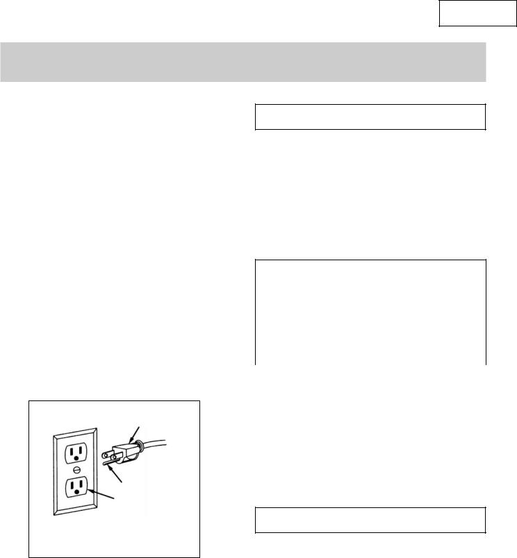
IN THE EVENT OF A MALFUNCTION OR BREAKDOWN, grounding provides a path of least resistance for electric current and reduces the risk of electric shock. This tool is equipped with an electric cord that has an equipment grounding conductor and a grounding plug. The plug MUST be plugged into a matching outlet that is properly installed and grounded in accordance with ALL local codes and ordinances.
DO NOT MODIFY THE PLUG PROVIDED. If it will not fit the outlet, have the proper outlet installed by an electrician.
IMPROPER CONNECTION of the equipment grounding conductor can result in electric shock. The conductor with the green insulation (with or without yellow stripes) is the equipment grounding conductor. If repair or replacement of the electric cord or plug is necessary, DO NOT connect the equipment grounding conductor to a live terminal.
CHECK with a qualified electrician or service personnel if you do not completely understand the grounding instructions, or if you are not sure if the tool is properly grounded.
USE ONLY 3-WIRE EXTENSION CORDS that have 3-prong plugs and 3-prong outlets that accept the tool’s plug as shown in Fig. A. Repair or replace damaged or worn cords immediately.
1
3
2
1-3-prong plug 2-properly grounded outlet 3-grounding prong
CAUTION: IN ALL CASES, MAKE CERTAIN THE RECEPTACLE IN QUESTION IS PROPERLY GROUNDED. IF YOU ARE NOT SURE IF IT IS, HAVE A CERTIFIED ELECTRICIAN CHECK THE RECEPTACLE.
GUIDELINES FOR USING EXTENSION CORDS
 WARNING
THIS PLANER IS FOR INDOOR USE ONLY. DO NOT EXPOSE TO RAIN OR USE IN DAMP LOCATIONS.
Make sure your extension cord is in good condition. When using an extension cord, be sure to use one heavy enough to carry the current your product will draw. An undersized cord will cause a drop in line voltage resulting in loss of power and overheating. The table below shows the correct size to be used according to cord length and nameplate ampere rating. If in doubt, use the next heavier gauge. The smaller the gauge number, the heavier the cord.
MINIMUM GAUGE FOR EXTENSION CORDS (AWG) (when using 120 V only)
Ampere Rating |
|
Total length in feet |
|
||||
|
|
|
|
|
|
|
|
|
Not |
|
|
|
|
|
|
More Than |
More Than |
25’ |
|
50’ |
100’ |
|
150’ |
0 |
6 |
18 |
|
16 |
16 |
|
14 |
6 |
10 |
18 |
|
16 |
14 |
|
12 |
10 |
12 |
16 |
|
16 |
14 |
|
12 |
12 |
16 |
14 |
|
12 |
Not Recommended |
||
Make sure your extension cord is properly wired and in good condition. Always replace a damaged extension cord or have it repaired by a qualified person before using it. Protect your extension cords from sharp objects, excessive heat and damp or wet areas.
Use a separate electrical circuit for your tools. This circuit must not be less than a #12 wire and should be protected with a 15 A time lag fuse. Before connecting the motor to the power line, make sure the switch is in the OFF position and the electric current is rated the same as the current stamped on the motor nameplate. Running at a lower voltage will damage the motor.
 WARNING
THIS TOOL MUST BE GROUNDED WHILE IN USE TO PROTECT THE OPERATOR FROM ELECTRICAL SHOCK.
SAVE THESE SAFETY INSTRUCTIONS
— 7 —
English
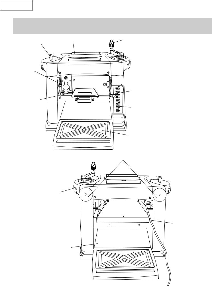
KNOW YOUR PLANER
Cap |
Tool storage |
|
ON/OFF switch
CAPACITIES
Cutting width 13"
Cutting height 6"
Depth of cutting 3/32"
Depth lock lever
Depth adjustment handle
|
17 |
|
6-1/2 |
|
|
|
16 |
|
6 |
15 |
Depth scale |
|
13 |
|
5-1/2 |
14 |
|
5 |
10 |
pointer |
4 |
||
|
12 |
|
|
11 |
|
3-1/2 |
9 |
|
|
8 |
|
3 |
|
|
|
7 |
|
2-1/2/2 |
|
|
|
6 |
|
2 |
5 |
Depth scale |
1 |
2 |
|
1-1/2 |
4 |
|
|
3 |
|
1/2 |
1 |
|
0 |
0 |
|
INCH |
CM |
|
Front extension table
Cord brackets
Carrying handle
Power cord
Main table
— 8 —

English
ASSEMBLY AND ADJUSTMENTS
UNPACKING |
ESTIMATED ASSEMBLY TIME 20 ~ 35 MINUTES |
Carefully unpack the planer and all its parts, and compare it to the list below. Do not discard the carton or any packaging until the planer is completely assembled.
 WARNING
IF ANY PART IS MISSING OR DAMAGED, DO NOT PLUG IN THE PLANER UNTIL THE MISSING OR DAMAGED PART IS REPLACED.
Bolts |
Power Cord Bracket |
Hex Key |
Setting Gauges |
Cap Bolt
Planer
Wrench |
Crank Handle |
|
Short |
Long |
Short |
Long |
|
Stand Legs |
Lower |
Lower |
Upper |
Mounting |
|
|
Crossbar |
Crossbar |
Crossbar |
Upper |
Hardware |
|
|
|
|
Crossbar |
|
— 9 —
English
ASSEMBLY AND ADJUSTMENTS_Continued
 WARNING
Never connect the plug to the power source outlet until all installations and adjustments are completed and you have read and understood the safety and operational instructions.
ASSEMBLY INSTRUCTIONS
Lift the tool from the packaging and place it on your workbench. Carefully open the front and rear extension tables and take out the loose parts bag and power cord.
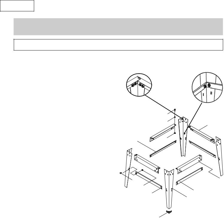
ASSEMBLE STAND (Fig. A)
1.Unpack all parts and sort by type and size. Refer to the parts list on page 18 for correct quantities.
2.Attach long upper crossbar (4) to top of
leg (1) and adjacent leg using carriage bolts (2) and nuts (5).
NOTE: Do not tighten bolts until step 7.
3.Attach long lower crossbar (3) to bottom of leg (1) and adjacent leg using carriage bolts and nuts.
4.Repeat on opposite side of stand.
5. Join the front and back of stand, using short upper |
6 |
(11) and lower (10) crossbars, carriage bolts and nuts.
6.Place end caps (7) on legs.
7. Place the stand on a level surface and make sure all legs are contacting the floor and are at similar angles to the floor. Tighten all bolts.
12
13
11
14
ASSEMBLE PLANER TO STAND
1.Carefully place planer on top of stand.
2.Line up the four mounting holes on tool base with those on the stand.
3.Fasten the planer to the stand using mounting bolts (12), washers (13) and nuts (14)(see Fig. A).
4.Tighten all nuts.
NOTE: DO NOT OVER TIGHTEN NUTS.
2 |
4 |
5
3
10
1
7
Fig. A
— 10 —
English
ASSEMBLY AND ADJUSTMENTS_Continued
Installing the Depth Adjustment Handle (Fig. 1)
1.Place the depth adjustment handle (1) on the right hand side, on top of the machine.
2.Insert the hex socket screw into the handle. Tighten.
3.Press the cap on the left hand side.
NOTE: The depth adjustment handle can be installed on either the right-hand side or left-hand side. The illustration shows the crank handle on the right-hand side.
Install Power Cord Brackets (Fig. 2)
Power cord brackets (1) are provided for convenient cord storage. Attach the power cord brackets to the back of the tool body, as shown, with two screws (2). Tighten.
1 |
13-In. Planer |
Fig. 1
1 |
2 |
Adjusting the Extension Table (Fig. 4, 5)
1.Pull out the cutterhead lock lever.
2.Unlock the head.
3.Turn the depth adjustment handle to raise the head.
4.Place a straight edge over the extension tables and the main table.
5.Press down the edge against the table extensions to remove any play.
6.If adjustment is required, fold up the extension table and loosen the nut (1) and adjust the bolt (2) until the tables are level.
Fig. 4
2
1
Fig. 5
 WARNING
To avoid injury from an accidental start-up, make sure the switch is in the OFF position and the plug is not connected to the power source.
Fig. 2
ADJUSTMENT
NOTE: This tool was accurately adjusted before shipping from the factory. Check the following accuracy and readjust them if necessary in order to obtain the best results in operation.
— 11 —
English
ASSEMBLY AND ADJUSTMENTS_Continued
Adjusting the Depth Scale (Fig. 6)
1.Try to plane a board.
2.Compare the measured thickness of the board to the reading on the depth scale (2).
3.If the reading on the depth scale is incorrect, loosen the screws (1) that tighten the pointer (3) and adjust until the proper measurement is displayed.
4.Test the reading again by planing another scrap wood. Double check it and re-adjust if necessary.
|
17 |
1 |
6-1/2 |
16 |
|
|
|
|
6 |
15 |
|
5-1/2 |
14 |
|
5 |
13 |
|
12 |
|
|
|
3 |
|
|
11 |
|
4 |
10 |
|
3-1/2 |
9 |
|
3 |
8 |
|
7 |
|
|
|
2 |
|
2-1/2 |
6 |
|
|
|
|
2 |
5 |
|
1-1/2 |
4 |
|
|
3 |
|
1 |
2 |
|
|
|
|
1/2 |
1 |
|
|
|
|
0 INCH |
CM 0 |
|
Fig. 6
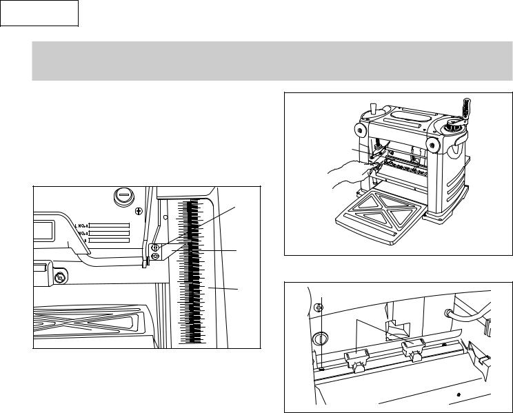
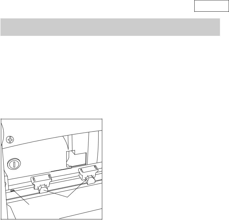
Setting the Knife Height (Fig. 7, 8)
1.Remove the two screws with a screwdriver, then remove the dust cover. (Fig. 13)
2.Loosen the eight hex-head screws (1) with supplied wrench.
3.Press the arbor lock latch and turn the cutterhead until exposing two hex bolts (1).
4.Place the knife setting gauge (2) (Fig. 8) on the cutterhead with both guides resting firmly against the knife.
5.Loosen or tighten the hex bolts (1) (Fig. 8) until the knife touches the knife setting gauge.
6.Fasten the eight hex-head screws with the supplied wrench.
7.Replace the dust cover and secure it with the two screws.
1
Fig. 7
1 |
2 |
Fig. 8
— 12 —
English
OPERATION
 WARNING
Never connect the plug to the power source outlet until all installations and adjustments are completed and you have read and understood the safety and operational instructions.
Remove the switch key whenever the saw is not in use. Place it in a safe place and out of reach of children.
Thickness Planer Operations
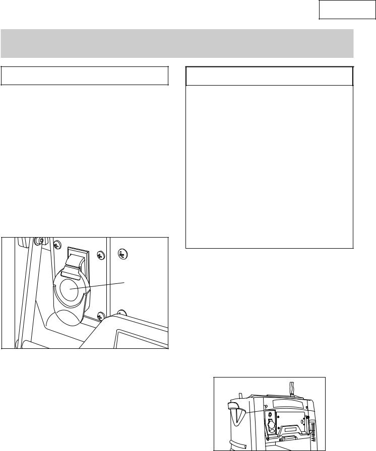
“ON/OFF” SWITCH (Fig. 9)
The keyed switch is intended to prevent unauthorized use of the planer.
1.To turn the planer ON insert the yellow key (1) into the key slot in the centre of the switch.
2.Push the key firmly into the slot, then push switch to the ON position to start the planer.
3.To turn the planer OFF push the switch to the down position.
4.Remove yellow safety key when saw is not in use to prevent unauthorized usage.
1
Fig. 9
 WARNING
1.Allow the motor to come up to full speed before starting cut.
2.Always feed the work in the direction that allows the planer blades to cut with the grain. Feeding against the grain will cause the blades to lift fibres from the work surface causing a fuzzy appearance.
3.Remove all foreign objects from the workpiece. Do not plane wood that is severely knotted or warped.
4.The planer works best with at least one flat surface. Place the flat surface downward on the table.
5.Do not plane more than 3 mm in one pass.
6.Proper depth of cut is judged by the width of the board and hardness of the board.
7.Make sure long boards are supported level with table at front and rear of the planer. Use extension roller stand if necessary.
8.Do not receive the board with your hands toward inside of the rear extension table.
9.If you need cutting to a specific height (3/4”, 1/4”, 1/2”). Move the right side of the height level to the desired position. (Fig. 12)
1.Pull out the cutterhead lock lever. (Fig. 10)
2.Unlock the cutterhead.
3.Lower the cutter head until it touches the workpiece.
4.Set the cutting depth dial to “0” mark.
5.Raise the cutterhead a little and remove the workpiece.
6.Adjust the depth of cut to the desired finished thickness of the board.
7.Lock the cutterhead.
8.Push in the cutterhead lock lever. (Fig. 11)
9.Start board under the infeed roller so it travels straight. When infeed roller takes hold, release board and stand aside (out of the way of any possible kickback).
10.If the board is long, place it on the top of the planer and roll it to the front for replaning.
Fig. 10
— 13 —

English
1 
Fig. 11
3/4 |
|
|
0 |
1/4 |
1/2 |
3/4" |
1/2" |
0 |
Fig. 12
NOTE:
1.Planing for a smooth finish as well as thickness is best accomplished by taking light cuts on the board.
2.For the best result, plane both sides of your workpiece to reach the desired thickness.
3.If snipe happens, (snipe is a depression made when the ends of the workpiece contact the cutters) make sure the extension tables and support stands are level with the main table and the flat side of the workpiece is against the tables.
4.For bowed workpiece, removing the bow with a jointer is recommended.
5.For cupped or warped workpieces, plane the top flat and then turn it over and plane the bottom flat.
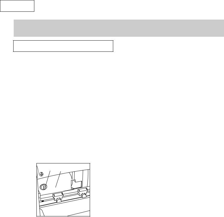
Changing Blades
NOTE: The blades changing accessories are stored in the tool storage.
1.Rotate the handle to lower down the cutterhead to 2” (50 mm) height.
2.Remove all screws to remove the dust hood and dust cover (1) (Fig. 13).
3.Press the arbor lock latch (2) and turn the cutter head until it exposes eight hex head screws (Fig. 14).
4.Remove the eight hex head bolts (3) with the supplied wrench (Fig. 15).
5.Carefully remove the hold-down plate (4) by lifting straight up (Fig. 15).
6.Carefully remove the blade (5) by lifting both ends straight up (Fig. 15).
7.The blade has two cutting edges. If using the other side of the blade or replacing the blade, place the blade on the cutterhead by locating the two slotted holes in the blade over the locating pins on the cutterhead (Fig. 15).
Fig. 13
1
Fig. 14
3
4
5
Fig. 15
 WARNING
To avoid injury from on accidental start-up, always turn the switch off and remove the power plug from the power source before changing the blades.
— 14 —
English
OPERATION_Continued
8.Slightly adjust the blade position so that it is positioned uniformly in the centre of cutterhead.
9.Replace the hold-down plate (4), screw the eight hex head-bolts (3) in, but do not tighten.
10.Place the blade setting gauges (6) on the cutterhead with both gauges resting firmly against the blade. (Fig. 16)
11.Turn both of the adjusting screws (7) until the blade touches the blade setting gauges.
12.Remove the blade setting gauges and then rotate the cutterhead to expose the eight hex-head blots (3). Tighten all bolts with supplied hex wrench.
13.Replace the dust hood and secure it with the two screws.
NOTE: The planer will not start until the dust cover and cutterhead guard are properly installed.
6
7
Fig. 16
— 15 —
English
MAINTENANCE
 WARNING
Never put lubricants on the blade while it is spinning. To avoid fire or toxic reaction, never use gasoline,
naphtha acetone, lacquer thinner or similar highly volatile solvents to clean the planer.
To avoid injury from unexpected starting or electrical shock, unplug the power cord before working on the tool. For your safety, this tool is double-insulated. To avoid electrical shock, fire or injury, use only parts identical to those identified in the parts list. Reassemble exactly as the original assembly to avoid electrical shock.
REPLACING CARBON BRUSHES (Fig. 17)
The carbon brushes furnished will last approximately 50 hours of running time, or 10,000 ON/OFF cycles. Replace both carbon brushes when either has less than 1/4” length of carbon remaining, or if the spring or wire is damaged or burned. To inspect or replace brushes, first unplug the tool. Then remove the black plastic cap (1) on the side of the motor (2). Remove the cap cautiously, because it is spring-loaded. Then pull out the brush and replace. Replace for the other side. To reassemble reverse the procedure. The ears on the metal end of the assembly go in the same slots the carbon part fits into. Tighten the cap snugly, but do not overtighten.
Make sure the belt is evenly seated all the way on the motor and drive pulley grooves.
Replace and secure right panel.
LUBRICATION
Motor and cutterhead bearings are sealed and need no lubrication.
Gears and elevation screws should be cleaned of debris and grease
The tables can be coated with a lubricant such as furniture wax, to make the workpiece feed smoother. Make sure the lubricant used does not affect the ability to finish the workpiece with varnish, sealer, etc. Do not use any silicone-base lubricants.
CLEAN PLANER
Keep planer clean. After 10 hours of operation, remove wood chips, dust, dirt and debris.
1 2
Fig 17
NOTE: To reinstall the same brushes, first make sure the brushes go back in the way they came out. This will avoid a break-in period that reduces motor performance and increases wear.
REPLACING V-BELT
Inadequate tension in the V-belt will cause the belt to slip from the motor pulley or drive pulley. A loose belt must be replaced. To replace V-belt:
Turn planer OFF and unplug from power source.
Loosen and remove screws on right panel. Remove panel.
Remove old belt by walking the belt from motor and drive pulleys alternatively. Gently pull the belt while turning the pulleys at the same time.
Replace with new belt. Walk the belt onto the pulleys in the reverse manner as when removing the belt.
— 16 —
 Loading...