


 Loading...
Projector
LP-WU9750B
User's Manual
Thank you for purchasing this product. Please read this manual before you operate your projector. Save it for future reference.

INDEX
Warning, Notices and Safety Instructions |
4 |
Notice |
4 |
Do not open |
4 |
Description pertaining to FCC Rules Part 15 |
4 |
About Waste Electrical and Electronic Equipment |
5 |
Sun light Warning |
5 |
Never look into the projector light source directly |
5 |
Electric shock |
6 |
Do not overload wall outlets/extension cords |
6 |
Cleaning |
6 |
Dampness, smoke, steam, dust, high temperature and direct |
6 |
exposure to sunlight |
|
Ventilation |
6 |
Intrusion of foreign objects |
6 |
Cooling fluid |
6 |
Carrying the projector |
7 |
Please install the projector on an even and stable surface |
7 |
Servicing |
7 |
Changing parts |
7 |
Power cord |
7 |
Notices you should read prior to the installation of the |
|
projector |
8 |
Take frequent breaks to let your eyes rest |
8 |
Installation environment for the projector |
8 |
Configurations for projector operation at high altitudes |
8 |
Protect the projector with care |
8 |
Keep the projector's ventilation inlets and outlets free from |
|
obstructions |
8 |
Positioning Precautions |
9 |
Caution for 3D |
10 |
LASER WARNING |
11 |
CLASS 3R LASER PRODUCT |
11 |
Laser Parameters |
11 |
Product labels |
12 |
Location of laser aperture |
15 |
Interlock switches |
15 |
Name and quantity of toxic/hazardous substances/elements |
|
contained in the product |
16 |
Projector parts and functions |
17 |
Front view |
17 |
Rear view |
18 |
Bottom view |
20 |
Range of effective remote control signal reception |
21 |
Installing batteries in the remote control |
21 |
Installation the projector. |
22 |
|
1. |
Orient the projector towards the screen |
22 |
2. |
Remove the lens PU foam on the projector |
22 |
3. |
Depending on your area, to select the correct input |
|
|
voltage. |
22 |
4. |
Connect the power cord to the projector |
22 |
5. |
Connect the projector to your PC and flip the switch |
|
|
to “׀” to turn on the power. |
22 |
6. |
Starting the projector up. |
23 |
7. Adjusting the projector's angle, Lens Shift, Zoom and
Focus |
23 |
8. Correcting keystoning caused by projection angle 23
9. Turning off the projector |
24 |
Throw distance |
25 |
Modes of installation |
25 |
Front Tabletop |
25 |
Front Ceiling |
26 |
Rear Tabletop |
26 |
Rear Ceiling |
26 |
Rear Tabletop with a Mirror |
26 |
Horizontal and vertical lens shift |
27 |
Moving the lens vertically |
27 |
Moving the lens horizontally |
27 |
Connecting the projector to other devices |
28 |
HDMI / DVI connection |
28 |
12V Trigger connection |
28 |
RGB connection |
29 |
SDI connection |
29 |
HDBaseT connection |
29 |
Turning on the projector |
30 |
Changing OSD language |
30 |
Adjusting screen orientation |
31 |
Front Ceiling |
31 |
Rear Tabletop |
31 |
Rear ceiling |
32 |
Adjusting the projector lens |
32 |
2
Remote control
OSD Menu Tree
OSD Description
MAIN
Input
PinP
PinP Selection
PinP Position
Color Space 3D
Magnify & Shift
No Signal
PICTURE
Picture Mode Brightness Contrast Color
Tint Sharpness
Noise Reduction
Color Temperature White Balance Aspect
Over Scan Position and Phase
Auto Adjust
LASER
Power Mode
Power Level
High Altitude
ADVANCED
Installation
Lens Control
Lens Memory
Lens Centering Gamma Pattern
Color Management Warping
Blanking Edge blending Memory
Dynamic Black
SETUP
Network OSD Setting
Infrared Remote Remote ID Start up logo Trigger
33 |
Auto Search |
58 |
|
|
Auto Power Off |
58 |
|
35 |
Direct Power On |
58 |
|
Language |
58 |
||
|
|||
38 |
AMX D.D. |
58 |
|
Web control/ Crestron Control |
58 |
||
38 |
|||
SERVICE |
59 |
||
38 |
Model Name |
59 |
|
39 |
Serial Number |
59 |
|
39 |
Software Version 1 / 2 |
59 |
|
39 |
Active Source |
59 |
|
40 |
Signal Format |
59 |
|
40 |
Laser Hours |
60 |
|
40 |
Thermal Status |
60 |
|
40 |
Lens Infomation |
60 |
|
41 |
Factory Reset |
60 |
|
41 |
Cleaning |
61 |
|
41 |
|||
42 |
Cleaning the Cabinet |
61 |
|
42 |
Cleaning the Lens |
61 |
|
42 |
|
|
|
42 |
Using the Kensington® Lock |
62 |
|
43 |
|
|
|
44 |
Simple troubleshooting |
63 |
|
44 |
|||
|
64 |
||
45 |
|
||
LED STATUS |
65 |
||
46 |
|||
46 |
Specifications |
66 |
|
47 |
Optional parts |
66 |
|
48 |
Suppored Signal Input Modes |
67 |
|
48 |
SDI formats |
68 |
|
48 |
Dimensions |
69 |
|
49 |
|
|
|
50 |
Communication settings |
70 |
|
50 |
RS-232 Communication |
70 |
|
50 |
|||
Connection |
70 |
||
51 |
|||
1. Protocol |
71 |
||
51 |
|||
2. Command format |
71 |
||
51 |
|||
3. Response code / Error code |
72 |
||
51 |
|||
Comand Control via the Network |
73 |
||
51 |
|||
Connection |
73 |
||
52 |
|||
Communication Port |
73 |
||
53 |
|||
Comand control settings |
74 |
||
53 |
|||
RS-232 Communication command table |
75 |
||
55 |
|||
|
|
||
55 |
|
|
|
56 |
Copyright information |
88 |
|
56 |
|||
|
|
||
57 |
Copyright |
88 |
|
57 |
Disclaimer |
88 |
|
57 |
TradeMark |
88 |
|
57 |
Warranty and after-service |
88 |
|
57 |
3
Warning, Notices and Safety Instructions
Warning, Notices and Safety Instructions
Notice
This product is intended for the adults who have the ability to operate this machine.
Please write down your projector model number and serial number and keep the information for maintenance purposes in the future. Should the equipment be lost or stolen, the information could also be used for the police report.
Model number: Serial number:
Please check the accessories that come with the projector with the following list. Should you find any missing accessory, contact your dealer immediately.
1. |
AC Power Cord US 125V |
4. |
Remote control |
7. |
Printed Manual |
10. |
WEEE Manual |
|||
2. |
AC Power Cord EU |
5. |
AA battery 2pcs |
8. |
EAC Document |
11. |
RS232 cable(cross) |
|||
3. |
Wire Remote Cable |
6. |
CD-ROM |
9. |
EU Recycle Sheet |
12. |
|
RGB cable |
||
|
|
|
|
|
|
|
|
|
|
|
Do not open
CAUTION |
RISK OF ELECTRIC SHOCK |
DO NOT OPEN |
CAUTION / TO REDUCE THE RISK OF ELECTRIC SHOCK |
DO NOT REMOVE COVER(OR BACK) |
NO USER-SERVICEABLE PARTS INSIDE |
REFER SERVICING TO QUALIFIED SERVICE PERSONNEL |
The lightning flash with an arrowhead within a triangle is intended to tell the user that inside this product may cause risk of electrical shock to persons.
The exclamation point within a triangle is intended to tell
the user that important operating and/or servicing instructions are included in the technical documentation for this equipment.
This is a Class A product. In a domestic environment this product may cause radio interference in which case the user may be required to take adequate measures.
Description pertaining to FCC Rules Part 15
This device complies with Part 15 of the FCC Rules. Operation is subject to the following two conditions: (1) this device may not cause harmful interference, and (2) this device must accept any interference received, including interference that may cause undesired operation.
This device has been tested and found to comply with the limits for a Class A digital device, pursuant to Part 15 of the FCC Rules. These limits are designed to provide reasonable protection against harmful interference in a residential installation.
This equipment generates, uses and can radiate radio frequency energy. If not installed and used in accordance with the instructions, may cause harmful interference to radio or television reception. However, there is no guarantee that interference will not occur in a particular installation. If this equipment does cause interference to radio or television reception, which can be determined by turning the equipment off and on, the user is encouraged to try to correct the interference by one or the following measures:
•Reorient or relocate the receiving antenna.
•Increase the separation between the equipment and receiver.
•Connect the equipment into an outlet on a circuit different from that to which the receiver is connected.
•Consult the dealer or an experienced radio/TV technician for help.
4

Warning, Notices and Safety Instructions
CAUTION:
Changes or modifications not expressly approved by the manufacturer void the user’s authority to operate the equipment.
This Class A digital apparatus meets all requirements of the Canadian ICES-003 Standards. Cet appareil numérique de la classe A est conforme à la norme NMB-003 du Canada.
About Waste Electrical and Electronic Equipment
 The mark is in compliance with the Waste Electrical and Electronic Equipment Directive 2002/96/EC (WEEE).The mark indicates the requirement NOT to dispose the equipment including any spent or discarded batteries or accumulators as unsorted municipal waste, but use the return and collection systems available. If the batteries or accumulators included with this equipment, display the chemical symbol Hg, Cd, or Pb, then it means that the battery has a heavy metal content of more than 0.0005% Mercury or more than, 0.002% Cadmium, or more than 0.004% Lead.
Sun light Warning
Avoid using this projector in direct sun light.
Sun light on the projector lens can severely damage the Digital Mirror Devices (DMD™).
Never look into the projector light source directly
When turn on the projector, make sure nobody's eye will effects by the projection of light. Always avoid to let eyes contact to the light.
As with any bright source, do not stare into the direct beam, RG2 IEC 62471-5:2015
Electric shock
To protect your projector, avoid turning on the projector during lightning storms and unplug it from the wall outlet. This will prevent sudden electrical surges caused by the lightning from damaging the projector.
5

Warning, Notices and Safety Instructions
Do not overload wall outlets/extension cords
Pay attention to the current load of the outlet you are using, be it wall outlet or extension cord outlet to prevent fire or electric shock.
Cleaning
When cleaning the projector, be sure to unplug it from the wall outlet to prevent electric shock.
Do not use liquid or aerosol cleaners. Use a dry/damp cloth with excessive moisture removed for cleaning. Be sure to use cleaning cloth designed to clean monitors for the projector to prevent damages to the projector casing due to abrasion.
Dampness, smoke, steam, dust, high temperature and direct exposure to sunlight
Do not operate the projector in environments where it could be expose to dampness, smoke, steam, dust, high temperature or direct sunlight. For example: bathroom, kitchen, adjacent to washing machine, damp basement rooms, electric heaters or similar environments. Keeping or operating the projector in the above-mentioned environment could lead to discoloration, mold formation, grease or damages to the projector.
Ventilation
The projector case is designed with slots and openings to remove the heat inside the projector so that it will not overheat and damage the components. Be sure to operate the projector in an environment with ideal ventilation and don't operate it on a sofa, rug or other closed-in environments that could obstruct ventilation.
Intrusion of foreign objects
Be sure to keep all foreign objects away from entering the projector because it could be exposed to hazardous voltages and cause parts to short circuit. This could in turn lead to fire hazard or electric shock. Examples of foreign objects include: cockroach, screws, liquid and so forth.
In addition, never spill liquid into the projector.
Cooling fluid
When the projector is damaged, cooling fluid may come out of internal radiator or the tank. Never touch and drink it. When the fluid are swallowed or contacted with your eyes, Please have doctor's medical examination immediately.
Carrying the projector
The projector net weight is 28kg(not include lens). When moving the projector on a cart, be sure to handle the cart with care as abrupt stops, jolts of excessive force or uneven ground could lead the projector to topple.
6

Warning, Notices and Safety Instructions
Please install the projector on an even and stable surface
Avoid placing the projector on unstable cart, tripod, table and so forth to prevent the projector from falling, becoming damaged or causing injuries.
Servicing
Should you encounter problem with the projector, please seek assistance from your local dealer or qualified service personnel. Do not attempt to service the projector by yourself so that you would not be exposed to high voltage or other potential hazards.
No service is allowed except by authorized personnel.
Should you encounter any of the following situation, please unplug your projector from the wall outlet and contact a qualified service personnel for assistance:
•Damaged power cord or power plug.
•If a foreign object has fallen into the projector or if you have spilled water or other liquid into the projector.
•If the projector has been dropped accidentally or damaged.
•If you experience noticeably poor performance or malfunctioning with the projector despite having followed instructions for normal operation.
Changing parts
Should any part of the projector be damaged, check with your servicing personnel that only manufacturer certified parts were used for replacement. Used of non-certified parts may result in damages to the projector or hazards such as fire or electric shock. After changing parts, be sure to remind the servicing personnel to perform safety inspections to ensure that the projector operates normally.
No maintenance allowed by end user, Do not open the cabinet. No user servicable part inside.
Power cord
Don't place the projector where the cord can be walked on. This may result in fraying or damage to the power cord, especially at the plug and the point of connection between the power cord and the projector.
Please use the power cord that comes with the projector or the type of power cord specified for the projector (refer to the descriptions printed on the power cord). If you are not sure of the power available at the region you are in, consult your local power company to prevent damages to the projector due to the use of wrong power cord or potential fire hazards due to current overload.
Depending on the country and region you are in, the voltage and type of socket of the wall outlet may be different from the projector. If you are unable to fit the power plug into the wall outlet, contact your local dealer and do not remove the extra pin on the power plug to forcibly fit it to the socket at the risk of your own safety.
Connect the ground terminal for the AC inlet of this unit to the ground terminal of the building using an appropriate power cord (bundled).
Install the projector where you can access the power outlet easily.
7
Warning, Notices and Safety Instructions
Notices you should read prior to the installation of the projector
Take frequent breaks to let your eyes rest
Prolonged viewing of the projector screen could strain your eyes. Please be sure to rest your eyes adequately.
Installation environment for the projector
You should avoid installing the projector at place of excessive dampness, dust or smoke. If installation in such environment is unavoidable, be sure to have the interior of the projector
cleaned routinely to prolong the projector's lifecycle. Cleaning of the projector's interior should only be performed by qualified service personnel dispatched by your local dealer and you should not attempt to clean the inside of the projector by yourself.
If other light source is directly projected onto the projector screen, the color of the picture from the projector will appear to be pale and the picture quality will be lower. In addition, your eyes would be more prone to fatigue. Therefore, it is recommended that the projector be installed in places without direct exposure to sunlight or other sources of intense light.
The ideal operating temperature range for the projector is between 0°C ~ 40°C (32°F ~ 104°F) The ideal storage temperature range for the projector is between -10°C~ 60°C (14°F ~ 140°F)
Configurations for projector operation at high altitudes
When operating the projector at higher altitudes, be sure to manually set the fan mode to "High" or it could shorten the life of the optical system in the projector. High altitude is defined as places being
1219 meters (4000 feet) or higher.
Please refer to " Page 49 : High Altitude "
Protect the projector with care
When placing the projector at a high position, be sure to secure the projector firmly so that it would not fall and cause injuries. Take care to protect the projector's lens from collision, abrasion or other damages. Be sure to close the lens cover or cover the projector with a dust cover if you need to store the projector or if it will not be used for an extended time.
Keep the projector's ventilation inlets and outlets free from obstructions
Note the direction of air flow at the designated spot of installation. Do not let the hot air released from the outlet flow back to the inlet as it will prevent proper cooling and lead to damage of the projector's internal structure.
In the event of high temperature due to malfunctioning of the internal cooling fan caused by clogging at the ventilation inlets and outlets, the projector will activate its automatic protection mode and shutdown. When this happens, it does not necessary mean that the equipment is malfunctioning. Try to unplug the power cord from the wall outlet and wait for approximately 15 minutes before operating the projector again (remember to remove the objects that have caused poor ventilation so that the projector will not go into the protection mode again).
Description: The regulation of temperature inside the projector by the cooling fan is automatic. And as such, the sound of cooling fan changing its operating speed does not imply that a problem has occurred with the projector.
8

Warning, Notices and Safety Instructions
If there has the obstacles on projector both sides.
|
|
Distance must |
|
|
Distance must |
|
||
|
|
|
|
|
||||
|
|
|||||||
|
|
≥30cm(11.8 inch) |
|
|
≥30cm(11.8 inch) |
|
||
|
|
|
|
|
|
|
|
|
|
|
|
|
|
|
|
|
|
|
|
|
|
|
|
|
|
|
If there has the obstacle on projector rear side.
Distance must |
Lens |
≥50cm(19.7 inch) |
Positioning Precautions
This projector can be installed 360° range (include portrait). But life of optical parts will be shorten as following situation:
1.If the projector installed when the lens faces downward.
2.If the projector installed when the IO connect side upward at the portrait situation.
90° |
Tilt area |
|
|
|
|
Portrait area |
|
|
|
|
|
|
|
|
|
|
|
|
|
|
|
|
|
|
|
|
|
|
|
|
|
|
|
|
|
|
|
|
|
|
|
180° |
0° |
270°
Not suggest to let the lens faces downward
Not suggest to let the IO side upward
9
Warning, Notices and Safety Instructions
Caution for 3D
•Don't let children view the 3D by themselves , please always be accompanied by an adult.
•Although more than six years old can view the 3D. But children may not tell you if they are feeling unwell when viewng 3D content, so always be sure to check with the child.
•When viewing 3D content, be sure you are at an appropriate distance from the front of the screen. Suggest keep at least three times the height of the screen away from the screen.
•Check that the settings are correct and that the 3D effect is being correctly applied. If the image is inversed and the left and right eye images are swapped, the 3D effect does not work, which could cause eye strain or cause you to feel unwell.
3D content not suitable for below situation, it could aggravate their pre-existing conditions.
•People with a history of photosensitive epilepsy.
•People has heart disease.
•Pregnant women.
•People with serious illnesses.
•People with a history of epileptic seizures.
Suggest stop to view the 3D, if has below situation:
•When you feel unwell , tired, sleep deprived, fatigued or inebriated,
•The 3D image doubled or not clear.
•Enjoying 3D content that rotates, rolls, or shakes, some person may feel they are moving and trigger a form of “sea sickness”.
•Take too long time for viewing 3D content, be sure to take regular breaks to avoid cause eyestrain.
10
Warning, Notices and Safety Instructions
LASER WARNING
This symbol indicates that there is a potential hazard of eye exposure to laser radiation unless the instructions are closely followed.
CLASS 3R LASER PRODUCT
This Laser Product is designated as Class 3R during all procedures of operation. LASER LIGHT - AVOID DIRECT EYE EXPOSURE.
Do not point laser or allow laser light to be directed or reflected toward other people or reflective objects.
Direct or scattered light can be hazardous to eyes and skin.
There is a potential hazard of eye exposure to laser radiation if the included instructions are not followed.
Caution – use of controls or adjustments or performance of procedures other than those specified herein may result in hazardous radiation exposure.
Laser Parameters
Wavelength |
450nm - 460nm (Blue) |
Mode of operation |
Pulsed, due to frame rate |
Pulse width |
0.74ms |
Pulse repetition rate |
240Hz |
Maximum laser energy |
0.376mJ |
Total internal power |
>100W |
Apparent source size |
>10mm, at lens stop |
Divergence |
>100 mili Radian |
11

Warning, Notices and Safety Instructions
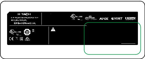
Product labels
Below drawing show the label's location.
|
CONTROL |
V |
H |
B/Cb/Pb |
G/Y |
R/Cr/Pr |
COMPUTER IN 1 |
INPUT |
AUTO ASPECT |
LENS |
|
|
CENTERING BLANK |
|
|||||||||
TRIGGER |
LAN |
|
|
COMPUTER IN 2 |
|
|
|
|
|
|
|
|
|
|
|
|
|
|
|
LENS |
FOCUS ZOOM |
||
|
|
|
|
|
|
|
|
MENU |
EXIT |
||
|
|
|
|
|
|
|
|
SHIFT |
|
||
REMOTE |
|
|
|
|
|
SDI IN |
OUT |
|
|
|
|
CONTROL |
HDBaseT |
HDMI 1 |
|
DVI-D |
|
HDMI 2 |
|
|
|
.Manufacturer’s ID
.Serial No.
.Hazard Warning Symbol, Aperture Label,
Certification Statement Label and Explanatory Label
AVOID EYE CONTACT TO THE LIGHT
TEMP. |
LIGHT |
STATUS |
POWER |
LP-WU9750B
12
Warning, Notices and Safety Instructions
|
|
|
|
|
|
|
|
|
|
|
100-130V |
50/60Hz 9.5A |
|
|
|
|
|
|
|
|
|
|
|
|
|
|
|
|
|
|
|||
|
|
|
|
|
|
|
|
|
|
|
This device complies with part 15 of the FCC rules. |
|
|
|
||
|
|
|
|
|
|
|
|
|
|
|
|
|
|
|||
|
|
|
|
|
|
|
|
|
|
|
Operation is subject to the following two conditions: |
|
|
|
||
|
|
|
|
|
|
|
|
|
|
|
|
|
|
|||
|
|
|
|
|
|
LP-WU9750B |
(1) this device may not cause harmful interference, and |
|
|
|
||||||
|
|
|
|
|
|
(2) this device must accept any interference received, |
|
|
|
|||||||
|
|
|
|
|
|
|
|
|
|
|
including interference that may cause undesired operation. |
|
|
|
||
|
|
|
|
|
|
|
|
|
|
|
CAN ICES-003(A) / NMB-003(A) |
|
|
|
||
200-240V |
50/60Hz 4.5A |
|
|
|
|
|
|
|
|
|||||||
|
|
|
|
|
|
|
|
KTL ZU10002-XXXXX |
Caution : Do not open the cover. No user-serviceable parts inside |
|||||||
|
|
|
|
|
|
|
|
|||||||||
|
|
|
|
|
|
|
|
|||||||||
|
|
|
|
|
|
|
|
MSIP-REM-DVP-LP-W9750B |
||||||||
|
|
|
|
|
|
|
|
Cuidado : no abra la tapa. Niguna parte interna es reparable por Usuario |
||||||||
|
|
|
|
|
|
|
Attention: Ne pas ouvrir le couvercle. Aucune pièce réparable par l'utilisateur |
|||||||||
|
|
|
|
|
|
|
|
|
|
|
'HOWD 9LGR 'LVSOD\ 6\VWHP |
Prudence : n'ouvrez pas la couverture. Aucune partie utile d'utilisateur à l'intérieur. |
||||
|
|
|
|
|
|
|
|
:8-,$1* /LPLWHG |
|
|
|
|
||||
|
|
|
$6 |
|
|
Hitachi Maxell, Ltd. |
MADE IN CHINA |
|||||||||
|
|
|
|
/3 :8 % |
|
5030 TOTSUKA-CHO,TOTSUKA-KU, |
FABRIQUE EN CHINE |
|||||||||
|
|
|
|
|
||||||||||||
Hitachi Europe Ltd. |
|
|
|
|
|
|
|
|
|
|||||||
|
|
|
|
|
|
|
|
YOKOHAMA, JAPAN |
HECHO EN CHINA |
|||||||
WhiteBrook Park, Lower Cookham Road, Maidenhead |
|
|
|
|
|
|
|
|
||||||||
|
|
|
|
|
|
|
|
|||||||||
3264623500 XXXX XXXX
>PC< CM-100-037
Self declaration - Conforming to IS 13252(Part 1): 2010, R-41011894
|
|
|
|
|
|
|
|
S.NO./S.NO. |
Code39 of Model |
|
|
|
|
|
|
|
|
*LP-WU9750B* |
|
|
|
|
|
|
|
Code39 of S/N |
|
|
Code39 of MAC Address |
|
|
|
|
*DCYMCSSSSS* |
|
|
MAC: XX:XX:XX:XX:XX:XX |
||
|
|
*DCYMCSSSSS* |
|
MAC:XX:XX:XX:XX:XX:XX |
|||
|
|
|
|
|
Code39ofMACAddress |
|
|
|
|
Code39ofS/N |
|||||
|
|
|
|
|
|
|
|
|
|
*LP-WU9750B* |
|
|
RR |
||
|
|
Code39ofModel |
|
|
RR |
||
|
|
|
|
|
|||
|
|
|
|
|
|
|
|
13

Warning, Notices and Safety Instructions a.Hazard Warning Symbol
b.Aperture Label c.Certification Statement Label d.Explanatory Label
d
LASER RADIATION
AVOID DIRECT EYE EXPOSURE CLASS 3R LASER PRODUCT Wavelength : 450-460 nm
Max. Pulse energy: 0.376 mJ, Pulse duration: 0.74 ms IEC/EN 60825-1:2007
RAYONNEMENT LASER
ÉVITER D’EXPOSER DIRECTEMENT LENS YEUX PRODUIT LASER DE CLASSE 3R
Longueur D’onde : 450-460nm
Énergie D’impulsion Max. : 0.376 mJ, Durée de L’impulsion : 0.74 ms IEC/EN 60825-1:2007
LASERSTRAHLUNG
DIREKTE EXPOSITION DER AUGEN VERMEIDEN LASERPRODUKT DER KLASSE 3R
Wellenlänge : 450-460 nm
Max. Pulsenergie: 0.376 mJ, Pulsdauer: 0.74 ms IEC/EN 60825-1:2007
a |
b |
|
LASER APERTURE |
|
OUVERTURE LASER |
|
LASERÖFFNUNG |
|
|
Complies with FDA |
CLASS 1 LASER PRODUCT |
performance standards |
|
for laser products |
IEC/EN 60825-1:2014 |
|
|
except for deviations |
PRODUIT LASER DE CLASSE 1 |
pursuant to Laser |
IEC/EN 60825-1:2014 |
Notice No. 50, dated |
LASERPRODUKT DER KLASSE 1 |
June 24, 2007 |
IEC/EN 60825-1:2014 |
c |
|
RISK GROUP 2
CAUTION
Possibly hazardous optical radiation emitted from this product.
Do not stare at operating lamp. May be harmful to the eyes.
GROUPE DE RISQUE 2 |
|
ATTENTION |
|
Rayonnements optiques potentiellement dangereux émis par ce produit. |
|
Ne regardez pas la lampe en fonctionnement. Peut être nocif pour les yeux. |
RG2 |
|
RISIKOGRUPPE 2 ACHTUNG
Dieses Gerät gibt möglicherweise gefährliche optische Strahlung aus.
Bei Betrieb nicht direkt in die Lampe blicken. Dies könnte Augenschäden verursachen.
14

Warning, Notices and Safety Instructions
Location of laser aperture
Below drawing is the laser aperture location. Be careful not to let the eye see the light directly.
Laser aperture
Interlock switches
This machine has interlock switches to protect the laser light leakage.
|
|
Switch will power-off the system when the Top cover is opened.
Switch Will power-off the system individually when the lens is removed or not install correctly.
15

16
Please refer to below Table for the names and contents of the toxic or hazardous substances or elements contained in electronic information products.
Marking Styles for Names and Contents of Toxic or Hazardous Substances or Elements
|
|
|
Toxic or hazardous Substances and Elements |
||||
|
|
|
|
|
|
|
|
|
Part Name |
Lead |
Mercury |
Cadmium |
Hexavalent |
Polybrominated |
Polybrominated |
|
(Pb) |
(Hg) |
(Cd) |
Chromium |
biphenyls |
diphenyl ethers |
|
|
|
||||||
|
|
|
|
|
(Cr(VI)) |
(PBB) |
(PBDE) |
|
|
|
|
|
|
|
|
|
Optical Engine |
|
|
|
|
|
|
|
Optical Module |
|
|
|
|
|
|
|
Fans assy |
|
|
|
|
|
|
|
Metal bracket |
|
|
|
|
|
|
|
Plastic bracket |
|
|
|
|
|
|
|
Metal (Copper Pillars, Copper Nut etc.) |
|
|
|
|
|
|
|
Temperature switch |
|
|
|
|
|
|
|
PCB Assy |
|
|
|
|
|
|
|
Cable |
|
|
|
|
|
|
|
Power Cord |
|
|
|
|
|
|
|
Power Inlet |
|
|
|
|
|
|
|
Remote controller |
|
|
|
|
|
|
O: Indicates that this toxic or hazardous substance contained in all of the homogeneous materials for this part is below the limit requirement in SJ/T11363-2006.
X: Indicates that this toxic or hazardous substance contained in at least one of the homogeneous materials used for this part is above the limit requirement in SJ/T113632006.
(Enterprises may further provide in this box technical explanation for marking "X" based on their actual conditions.)
of quantity and Name product the in |
and Notices Warning, |
substances/elements toxic/hazardous |
Instructions Safety |
contained |
|

Projector parts and functions
Projector parts and functions
Front view
LED Indicator
Infrared receiver
Lens
Ventilation inlet
The internal cooling fan draws cool 


 air from the ventilation inlet into the


projector.
Ventilation slot
The hot air generated inside the projector is dispersed through the ventilation slot. Make sure the ventilation slot is free from obstruction.
Adjustable foot
Adjust the height and angle of the projector with the adjustable foot
|
|
|
|
|
|
|
|
|
|
|
|
|
|
|
|
|
|
|
|
|
|
|
|
|
|
|
|
|
|
|
|
|
|
|
|
|
|
|
|
|
|
|
|
|
|
|
|
|
|
|
|
TEMP. |
|
|
LIGHT |
|
|
STATUS |
|
|
POWER |
||||||
|
|
|
|
|
|
|
|
|
|
|
|
|
|
|
|
|
POWER (LED)
The indicator that shows the projector's power status.
STATUS (LED)
The indicator that shows the projector's standby status.
LIGHT (LED)
The indicator that shows the projector is on or off.
TEMP. (LED)
The indicator that shows the projector's error message.
17

Projector parts and functions
Rear view
|
Projector Keypad |
|
Infrared sensor |
Power inlet |
|
Ventilation outlet |
Power switch |
|
|
׀ -> on |
|
Adjustable foot |
О -> off |
|
|
Voltage Selector |
|
Adjustable foot |
(Default at 115V) |
|
IO Control |
||
|
STANDBY/ON 

Use this button to start up or shut down the projector .
INPUT
Used to toggle between different input signal source.
AUTO
Auto adjust the signal synchroniztion.
ASPECT
Adust the aspect ratio. Refer to “ Page 45 : Aspect “
LENS CENTERTNG
Press this button to center the lens and calibrate the parameter of lens shift, focusing and zooming.
Displays or hides the OSD adjustment screen.
▲▼▼▲ BUTTONS
Use these buttons to scroll, configure or adjust items on the OSD or toggle between different pictures.
ENTER
Press to confirm the changed settings
EXIT
Exit the OSD adjustment screen or return to previous osd level.
LENS SHIFT
Adjust the projected image posion.
FOCUS
Adjust the projected image's focus.
BLANK
Press this button display the blank image.
MENU
ZOOM
Zoom in or zoom out the projected image.
18

|
|
Projector parts and functions |
||
COMPUTER IN 2 |
|
|
|
|
Connects to five BNC inputs for PC (R/B/G/H/V) or for component (YPbPr) |
|
|
|
|
picture source and channel (Hs, Vs) source. |
|
|
|
|
CONTROL |
COMPUTER IN 1 |
|||
Standard 15-pin VGA connection socket to |
||||
9-pin D-sub socket. Connects your PC or |
connect to RGB, high-definition component input |
|||
automatic home theater /control system. |
or PC. The projector will automatically detect the |
|||
|
|
resolution of the input signal. |
||
TRIGGER |
|
|
|
|
|
|
|
||
(3.5-mm, mini phone jack) |
|
|
|
|
Offers 12 (+/- 1.5) V of output for |
|
|
|
|
350mA monitor relay with short |
|
|
|
|
circuit protection. |
|
|
|
|
To keep with cover while not in use. |
|
|
|
|
|
|
|
|
|
|
|
|
|
|
|
CONTROL |
V |
H |
B/Cb/Pb |
G/Y |
R/Cr/Pr |
COMPUTER IN 1 |
|
TRIGGER |
LAN |
|
|
COMPUTER IN 2 |
|
|
|
|
|
|
|
|
|
|
|
||
REMOTE |
|
|
|
|
|
SDI IN |
OUT |
|
CONTROL HDBaseT |
HDMI 1 |
|
DVI-D |
|
HDMI 2 |
|||
REMOTE |
|
|
|
|
SDI IN/OUT |
|
|
|
CONTROL |
|
|
|
|
|
|
||
|
|
|
|
Serial digital interface, use BNC |
|
|||
Usable wired-remote-control |
|
|
|
|
||||
|
|
|
connects input or output the picture. |
|
||||
with accessory cable. Available |
|
|
|
HDMI 1 & 2 |
|
|
||
for Niles or Xantech IR repeater |
|
|
|
|
|
|||
systems. |
|
|
|
|
HDCP compatible digital picture input; connects |
|||
HDBaseT |
|
|
|
|
||||
|
|
|
|
to sources using HDMI or DVI. |
|
|||
HDBaseT is a technology to transmit image, |
|
|
DVI-D |
|
|
|||
sound, ethernet or serial control signal via |
|
|
|
|
|
|
||
LAN cable. |
Connect to DVI source. |
|
IO Control (Input / Output)
19

Projector parts and functions
Bottom view
500,0
300,0
150,0
576,0 


150,0
Mounting bracket screw hole
These screw holes are used to mount the projector to its designated mounting bracket using 6 M4x16 screws. The dimensions of the screw holes are shown in the picture below.
Adjustable foot
Adjust the height and angle of the projector with the adjustable foot
20
Projector parts and functions
Range of effective remote control signal reception
The diagram below illustrates the range of effective remote control signal reception (Unused new battery).
40°
40°
12m
Note: Avoid placing the remote control at places of high temperature or humidity as it could cause the remote
control to malfunction.
Installing batteries in the remote control


-
+ |
- |
+ |
|


 +
+


1.Remove the cover by sliding it in the direction indicated by the arrow.
2.Insert two new AA batteries (observe the polarity).
3.Replace the cover.
Note1: Be sure to insert the batteries in the corresponding orientations to match the polarities.
Note2: Do not mix new batteries with used batteries as it would shorten the life of new batteries or cause leakage. Note3: Only used AA batteries as instructed; do not attempt to insert different types of batteries into the remote control. Note4: If the remote is going to be unused for long periods of time, be sure to remove the batteries to prevent leakage,
which could damage the remote control.
Note5: The liquid contents in the batteries is harmful to the skin; do not touch the leakage with your bare hands directly. When installing fresh batteries, be sure to clean up the leakage thoroughly.
Note6: Under most circumstances, you only need to point the remote control towards the screen and the IR signal would be reflected off the screen and picked up by the IR sensor on the projector. But under specific circumstances, the projector may fail to receive signals from the remote control due to environmental factors. When this happens, orient the remote control at the projector and try again.
Note7: If the range of effective remote control signal reception decreases or if the remote control stops working, replace the batteries.
Note8: If the infrared receiver is exposed to fluorescent lamp or strong sunlight, the remote control may not operate normally.
Note9: Refer to the regulations enforced by your local government on the disposal of used batteries; improper disposal could damage the environment.
21
Installation of the Projector
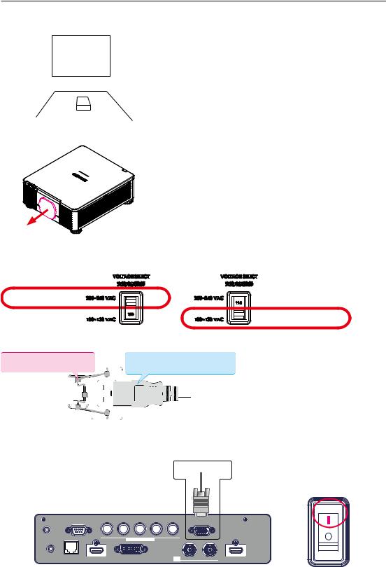
Installation the projector.
1. Orient the projector towards the screen
Screen
2.Remove the lens PU foam on the projector
3.Depending on your area, to select the correct input voltage.
Select 200-240V
Select 100-130V
4. Connect the power cord to the projector
Secure the power plug by locking the plug holder clamp.
Connect the female side of the power cord to power input socket of projector
5. Connect the projector to your PC and flip the switch to “׀” to turn on the power.
Desk Top or Notebook
|
CONTROL |
V |
H |
B/Cb/Pb |
G/Y |
R/Cr/Pr |
COMPUTER IN 1 |
|
TRIGGER |
LAN |
|
|
COMPUTER IN 2 |
|
|
|
|
|
|
|
|
|
|
|
||
REMOTE |
|
|
|
|
|
SDI IN |
OUT |
|
CONTROL |
HDBaseT |
HDMI 1 |
|
DVI-D |
|
HDMI 2 |
22

Installation of the Projector
6. Starting the projector up.
Press the  button on the projector or the
  button on the remote control to start up the projector.
7. Adjusting the projector's angle, Lens Shift, Zoom and Focus
a. Please use the adjustable feet to change the angle of the projector in order to achieve the most suitable angle for projection on the screen.
b. Adjusting the lens by horizontal and vertical lens shift and adjust Zoom and Focus of lens Method 1: Use the Keypad of
Lens Shift ▲▼◄► Focus 

Zoom
LENS SHIFT
Method 2: Press the  button on the remote control to access Lens Control-Lens Shift. Use the ▲▼◄► buttons to adjust the horizontal or vertical position of the lens. Then press ENTER to adjust the Zoom and Focus of the lens.
Press Lens Shift once to adjust Lens Shift
Lens Control
Shift
Enter
[Enter] Zoom/Focus Adjustment
Enter
Press Enter to adjust the Zoom and Focus
Lens Control
Zoom
Focus
[Enter] Shift Adjustment
|
MENU |
Method 3: Press the MENU button on the remote control or |
Keypad and choose Advanced |
Lens Control selected, then use the ▲▼◄► buttons to adjust the horizontal or vertical position of the lens. If want to adjust Zoom and Focus.
Press ENTER to adjust it.
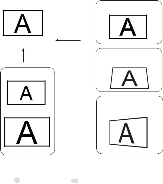
8.Correcting keystoning caused by projection angle
a.To adjust keystoning, press the MENU button on the remote control and choose Advanced
Warping Keystone adjust and use ▼▲ buttons to adjust Vertical Keystone. Refer to fig3 on next page.
b.To adjust keystoning, press the MENU button on the remote control and choose
Advanced Warping Keystone adjust and use▲▼buttons to adjust Horizontal Keystone. Refer to Fig 4 on next page.
23
Installation of the Projector
The picture after adjust
Fig 1
Focus
Adjust
Adjust |
Fig 3 |
|
Vertical Keystone |
||
|
Zoom Out
Fig 4
Horizontal Keystone
Zoom In
9. Turning off the projector
Press the  button on the projector or the STANDBY button on the remote control. The message will appear on the screen. Press the button again while the message appears. When the projector has been turned off, the cooling fan will remain in operation for approximately 10 seconds.
24
Installation of the Projector
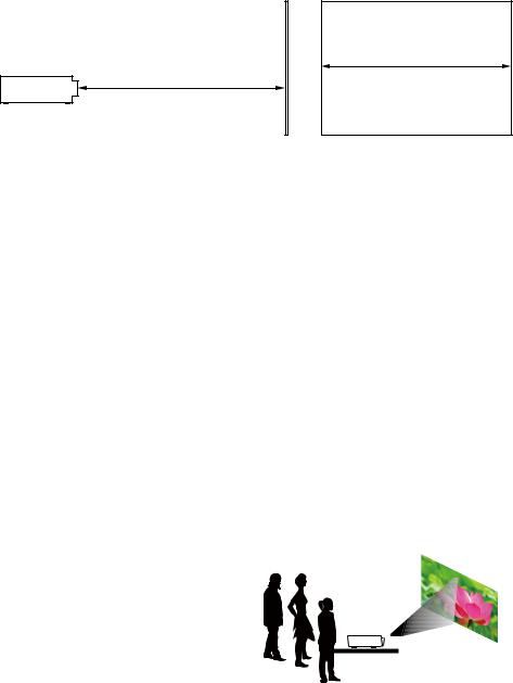
Throw distance
Throw Distance (TD) = Screen Width (W) x Throw Ratio (TR)
Screen Width(W)
Throw Distance(TD)
Coupled with the available projection lenses, the projector offers the following throw ratios:
• FL-920(FL-900) (0.32 : 1 100-350inch)
• USL-901 (0.76~0.95 : 1 50-600inch)
• SL-902 (1.14~1.72 : 1 |
50-600inch) |
• SD-903 (1.61~2.44 : 1 |
50-600inch) |
• ML-904 (2.38~3.64 : 1 |
50-600inch) |
• LL-905 (3.47~5.63 : 1 |
50-600inch) |
• UL-906 (5.53~8.79 : 1 |
50-600inch) |
Note:
Projection lenses are optional accessories. Please contact your local dealer to acquire the projection lens that suits your need most.
Modes of installation
•Install the projector in an environment below 40°C (104°F). The projector should be kept clear from sources of heat and / or ventilation openings of air conditioner.
•The projector should be kept away from devices that emit electromagnetic energy, such as motor and transformer. Common devices that emit electromagnetic energy include slideshow system, speakers, power amplifiers and elevators.
•If you choose to install the projector on the ceiling, be sure to use the ceiling installation components manufactured by manufacturer-certified vendors. For details, please contact your local dealer.
Front Tabletop
Advantages: easy to install can be easily moved or adjusted easy to operate.
Disadvantage: occupies floor space and limits seating capacity.
Lotus
25

Installation of the Projector
Front Ceiling
Refer to " Page 31 : Front Ceiling "
Advantage: does not occupy floor space does not draw attention to it.
Eliminates the possibility that someone would accidentally move the projector.
Disadvantage: stricter installation requirements and conditions; care should be taken during the installation
to ensure the projector has been securely mounted.
operation of the projector becomes inconvenient without the remote control.
Lotus
Rear Tabletop
Refer to " Page 31 : Rear Tabletop "
Advantage: the projector is completely hidden from plain view
the projector can be easily operated this setup usually offers better reduction of ambient noise.
Disadvantage: requires an additional room for installation relatively higher costs for installation.
Lotus
Rear Ceiling
Refer to " Page 32 : Rear ceiling "
Advantage: the projector is completely hidden from plain view this setup usually offers better reduction of ambient noise.
Disadvantage: requires an additional room for installation. Stricter installation requirements and conditions; care should be taken during the installation to ensure the projector has been securely mounted.
operation of the projector becomes inconvenient without the remote control.
Lotus
Rear Tabletop with a Mirror
If you wish to have a rear projection setup with limited space to the rear of the projector, you can use a mirror to reflect the light path.
However, both the projector and the mirror have to be precisely located. If you are considering such installation, please contact your dealer for assistance.
Advantage: the projector is completely hidden from plain view this setup usually offers better reduction of ambient noise.
Disadvantage: requires an additional room for installation relatively higher costs for installation.
Screen Mirror
26

Installation of the Projector
Horizontal and vertical lens shift
In addition to using the adjustable feet to adjust projection angle, you can also use the Lens Shift function to adjust the projected picture.
Moving the lens vertically
The distance of vertical lens movement is +60% , -22% of the screen height in both directions. For instance, if you are using a 2.15m × 1.35m(100") screen, you will be able to move the picture upwards no more than 81cm or downwards no more than 29.7cm.
Range of vertical lens shift adjustment
Range of vertical lens shift adjustment
This illustration shows normal vertical lens shift without the use of special specification lens or projector.
Note: Please make sure the center of lens is rectangular to the center of the screen.
The value indicates in the case of SD-903 lens.
Moving the lens horizontally
The distance of horizontal lens movement is 10% of the screen width in both directions. For instance, if you are using a 2.15m × 1.35m(100") screen, you will be able to move the picture left or right by no more than 21.5cm.
H: Range of Horizontal lens shift adjustment
|
|
H |
|
|
|
|
|
|
|
|
|
|
H |
||
|
|
|
|
|
|||||||||||
|
|
|
|
|
|
|
|
|
|
|
|
|
|
|
|
|
|
|
|
|
|
|
|
|
|
|
|
|
|
|
|
|
|
|
|
|
|
|
|
|
|
|
|
|
|
|
|
|
|
|
|
|
|
|
|
|
|
|
|
|
|
|
|
|
|
|
|
|
|
|
|
|
|
|
|
|
|
|
|
|
|
|
|
|
|
|
|
|
|
|
|
|
|
|
|
|
|
|
|
|
|
|
|
|
|
|
|
|
|
|
|
|
|
|
|
|
|
|
|
|
|
|
|
|
|
|
|
|
|
|
|
|
|
|
|
|
|
|
|
|
|
|
|
|
|
|
|
|
|
|
|
|
|
|
|
|
|
|
|
This illustration shows normal horizontal lens shift without the use of special specification lens or projector.
Note: when the lens is in the neutral position (i.e. without horizontal or vertical shift), the center of the projection should be aligned with the center of the screen.
The value indicates in the case of SD-903 lens.
27
Loading...