


NEED MORE INFO ON THE DTV TRANSITION? See page 34 in this Operating Guide and please visit www.dtvtransition.org
Alpha Series LCD Flat Panel HDTV Operating Guide for L42A403 & L32A403
IMPORTANT SAFETY INSTRUCTIONS ...................................................................... |
2-5 |
FIRST TIME USE ...................................................................................................... |
6-17 |
THE REMOTE CONTROL ......................................................................................... |
18-21 |
ON-SCREEN DISPLAY .......................................................................................... |
22-34 |
USEFUL INFORMATION ........................................................................................ |
35-41 |
LIMITED WARRANTY .................................................................................................... |
42 |
END USER LICENSE AGREEMENT FOR HITACHI DTV SOFTWARE ............. |
43-48 |
APPENDIXES ................................................................................................................. |
49 |
INDEX ............................................................................................................................. |
50 |
READ THE ENCLOSED INSTRUCTIONS CAREFULLY. KEEP THIS OPERATING GUIDE FOR FUTURE REFERENCE. Record the model name and serial number of your LCD Television for future reference.
MODEL NAME. ____________________ SERIAL NO. ________________________
This information is located on the back and right side of the television.

Important Safety Instructions
SAFETY POINTS YOU SHOULD KNOW ABOUT YOUR HITACHI LCD TELEVISION
Our reputation has been built on the quality, performance, and ease of service of Hitachi LCD televisions.
Safety is also foremost in our minds in the design of these units. To help you operate these products properly, this section illustrates safety tips which will be of benefit to you. Please read it carefully and apply the knowledge you obtain from it to the proper operation of your Hitachi
LCD television.
READ BEFORE OPERATING EQUIPMENT
Follow all warnings and instructions marked on this LCD television.
1.Read these instructions.
2.Keep these instructions.
3.Heed all warnings.
4.Follow all instructions.
5.Do not use this apparatus near water.
6.Clean only with a dry cloth.
7.Do not block any ventilation openings. Install in accordance with the manufacturer’s instructions.
8.Do not install near any heat sources such as radiators, heat registers, stoves, or other apparatus (including amplifiers) that produce heat.
9.Do not defeat the safety purpose of the polarized or groundingtype plug. A polarized plug has two blades with one wider than the other. A grounding type plug has two blades and a third grounding prong. The wide blade or the third prong are provided for your safety. If the provided plug does not fit into your outlet, consult an electrician for replacement of the obsolete outlet.
10.Protect the power cord from being walked on or pinched particularly at plugs, convenience receptacles, and the point where they exit from the apparatus.
11.Only use the attachments/accessories specified by the manufacturer.
12.Use only with the cart, stand, tripod, bracket, or
table specified by the manufacturer, or sold with the apparatus. When a cart is used, use caution when moving the cart/apparatus combination to avoid injury from tip-over.
13.Unplug this apparatus during lightning storms or when unused for long periods of time.
14.Refer all servicing to qualified service personnel. Servicing is required when the apparatus has been damaged in any way, such as power-supply cord or plug is damaged, liquid
Power source
The lightning flash with arrowhead symbol, within an equilateral triangle, is intended to alert the user to the presence of uninsulated
“dangerous voltage” within the product’s enclosure that may be of a sufficient magnitude to constitute a risk of electric shock to a person.
The exclamation point within an equilateral triangle, is intended to alert the user to the presence of important operating and maintenance
(servicing) instructions in the literature accompanying the appliance.
has been spilled or objects have fallen into the apparatus, the apparatus has been exposed to rain or moisture, does not operate normally, or has been dropped.
15. Televisions are designed to comply with the recommended safety standards for tilt and stability. Do not apply excessive pulling force to the front, or top, of the cabinet which could cause the product to overturn resulting in product damage and/or personal injury.
16.Follow instructions for wall, shelf or ceiling mounting as recommended by the manufacturer.
17.An outdoor antenna should not be located in the vicinity of overhead power lines or other electrical circuits.
18.If an outside antenna is connected to the receiver be sure the antenna system is grounded so as to provide some protection against voltage surges and built up static charges. Section 810 of the National Electric Code, ANSI/NFPA No. 70-1984, provides information with respect to proper grounding for the mast and supporting structure, grounding of the lead-in wire to an antenna discharge unit, size of grounding connectors, location of antenna discharge unit, connection to grounding electrodes and requirements for the grounding electrode.
NOTE To the CATV system installer: This reminder is provided to call the CATV system installer’s attention to Article 82044 of the NEC that provides guidelines for proper grounding and, in
particular, specifies that the cable ground shall be connected to the grounding system of the building, as close to the point of cable entry as practical.
This LCD television is designed to operate on 120 volts 60 Hz, AC current. Insert the power cord into a 120 volt 60 Hz outlet. The mains plug is used as the disconnect device and shall remain readily operable.
To prevent electric shock, do not use the LCD television’s (polarized) plug with an extension cord, receptacle, or other outlet unless the blades and ground terminal can be fully inserted to prevent blade exposure.
Never connect the LCD television to 50 Hz, direct current, or anything other than the specified voltage.
This television’s factory default settings as shipped meet Energy Star requirements.
Please see the ENERGY OPTIONS section of this operating guide for more energy saving tips.
Caution
Never remove the back cover of the LCD television as this can expose you to very high voltages and other hazards. If the television does not operate properly, unplug the LCD television and call your authorized dealer or service center.
Adjust only those controls that are covered in the instructions, as improper changes or modifications not expressly approved by
Hitachi could void the user’s warranty.
2

Important Safety Instructions
Warning
•To reduce the risk of fire or electric shock, do not expose this apparatus to rain or moisture.
•The LCD television should not be exposed to dripping or splashing and objects filled with liquids, such as vases, should not be placed on the television.
•This apparatus shall be connected to a mains socket outlet with a protective earthing connection.
Public viewing of copyrighted material
Public viewing of programs broadcast by TV stations and cable companies, as well as programs from other sources, may require prior authorization from the broadcaster or owner of the video program material.
This product incorporates copyright protection technology that is protected by U.S. patents and other intellectual property rights. Use of this copyright protection technology must be authorized, and is intended for home and other limited payper-view uses only unless otherwise authorized. Reverse engineering or disassembly is prohibited.
Lead/Mercury Notice
Hg |
This product contains lead and one or more non-replaceable mercury backlights. Do not put in trash. Recycle or dispose of |
according to applicable laws. For product recycling and disposal information, contact your local government agency or visit www. |
|
|
eiae.org (in USA) or www.epsc.ca (in Canada). FOR MORE INFORMATION, CALL 800-HITACHI. |
FEDERAL COMMUNICATIONS COMMISSION NOTICE
This equipment has been tested and found to comply with the limits for a Class B digital device, pursuant to Part 15 of the FCC Rules. These limits are designed to provide reasonable protection against harmful interference in a residential installation. This equipment generates, uses and can radiate radio frequency energy and if not installed and used in accordance with the instructions, may cause harmful interference to radio communications. However, there is no guarantee that interference will not occur in a particular installation. If this equipment does cause harmful interference to radio or television reception, which can be determined by turning the equipment off and on, the user is encouraged to try to correct the interference by one or more of the following measures:
•Reorient or relocate the receiving antenna.
•Increase the separation between the equipment and the receiver.
•Connect the equipment into an outlet on a circuit different from that to which the receiver is connected.
•Consult the dealer or an experienced radio/television technician for help.
This device complies with Part 15 of the FCC Rules. Operation is subject to the following two conditions :
(1) This device may not cause harmful interference and (2) This device must accept any interference received, including interference that may cause undesired operation.
Modifications
The FCC requires the user to be notified that any changes or modifications made to this device that are not expressly approved by Hitachi
Home Electronics (America), Inc, may void the user’s authority to operate the equipment.
Cables
Connections to this device must be made with shielded cables with metallic RFI/EMI connector hoods to maintain compliance with FCC Rules and Regulations.
Any cables that are supplied with the system must be replaced with identical cables in order to assure compliance with FCC rules. Order Hitachi spares as replacement cables.
This LCD Television receiver will display television closed captioning, ( or ), in accordance with paragraph 15.119 and 15.122 of the FCC rules.
NOTE INDUSTRY CANADA AGENCY REGULATORY INFORMATION
Cable Compatible Television ApparatusTèlèvision câblocompatible, Canada.
Declaration of Conformity
This device complies with part 15 of the FCC Rules. Operation is subject to the following two conditions : (1)This device may not cause harmful interference and (2)This device must accept any interference received, including interference that may cause undesired operation.
For questions regarding this declaration, contact:
Hitachi Home Electronics (America), Inc. 900 Hitachi Way
Chula Vista, CA 91914-3556 Tel. 800-448-2244(800-HITACHI) ATTN: Customer Relations
•VGA and XGA are trademarks of International Business Machines Corporation.
•VESA is a registered trademark of the Video Electronics Standard Association.
•HDMI, the HDMI logo and High-Definition Multimedia Interface are trademarks of registered trademarks of HDMI Licensing LLC.
3

Important Safety Instructions
Congratulations on your purchase! As you enjoy your new product, please keep these safety tips on mind:
THE ISSUE
•The home theater entertainment experience is a growing trend and larger flat displays are popular purchases. However, flat panel displays are not always supported on the proper stands or installed according to the manufacturer’s recommendations.
•Flat Panel displays that are inappropriately situated on dresser, bookcases, shelves, desks, speakers, chest or carts may fall over and cause injury.
HITACHI CARES!
•The consumer electronics industry is commited to making home entertainment enjoyable and safe.
TUNE INTO SAFETY
•One size does NOT fit all. Follow the manufacturer’s recommendations for the safe installation and use of your flat panel display.
•Carefully read and understand all enclosed instructions for proper use of this product.
•Don’t allow children to climb on or play with furniture and television sets.
•Don’t place flat panel displays on furniture that can easily be used as steps, such as a chest of drawers.
•Remember that children can become excited while watching a program, especially on a “larger than life” flat panel display. Care should be taken to place or install the display where it cannot be pushed, pulled over, or knocked down.
•Care should be taken to route all cords and cables connected to the flat panel display so that they cannot be pulled or grabbed by curious children.
WALL MOUNTING: IF YOU DECIDE TO WALL
MOUNT YOUR FLAT PANEL DISPLAY, ALWAYS:
•Use a mount that has been recommended by the display manufacturer and/or listed by an independent laboratory (such as UL, CSA, ETL).
•Follow all instructions supplied by the display and wall mount manufacturers.
•If you have any doubts about your ability to safely install your flat panel display, contact your retailer about professional installation.
•Make sure that the wall where you are mounting the display is appropriate. Some wall mounts are not designed to be mounted to walls with steel studs
or old cinder block construction. If you are unsure, contact a professional installer.
• A minimum of two people are required for installation. Flat panel displays can be heavy.
4
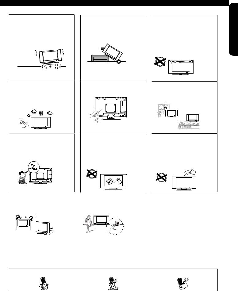
PRECAUTIONS AND REMINDERS
Do not place the unit on uneven surfaces, this may drop or damage the unit, it may also cause personal injury.
Unplug immediately if there is a malfunction on the TV like no picture, no video/audio or if there is smoke and bad odor coming from the TV.
Don’t throw any objects inside the TV like metals, coins or any other flammable materials.
Unplug immediately if any foreign materials falls into the TV or if the TV fell down.
Do not open the TV cabinet.
Remember to unplug the AC cord from the AC outlet before cleaning. Do not use liquid cleaners or aerosol cleaners to clean the display.
Do not cover or block any vents and openings of the TV. Inadequate ventilation may shorten the life of the display unit and cause overheating.
Avoid direct sunlight, dusty, high humidity and smoke locations.
Do not place the TV near water, such as bathtub, shower rooms, kitchen sink, laundry tub or swimming pool. Avoid liquid containers on top of the unit.
Don’t place the TV in confined |
|
Make sure to |
unplug the unit |
|||||
spaces or inside a box when the |
|
when not in use for a long period |
||||||
TV is operating. |
|
of time (days). |
|
|
|
|||
|
|
|
|
|
|
|
|
|
|
|
|
|
|
|
|
|
|
|
|
|
|
|
|
|
|
|
|
|
|
|
|
|
|
|
|
|
|
|
|
|
|
|
|
|
|
|
|
|
|
|
|
|
|
|
|
|
|
|
|
|
|
|
USE TIME FIRST
 Notice for Remote Controller
Avoid dropping the unit. Avoid liquids on it. Avoid aerosol cleaners.
5
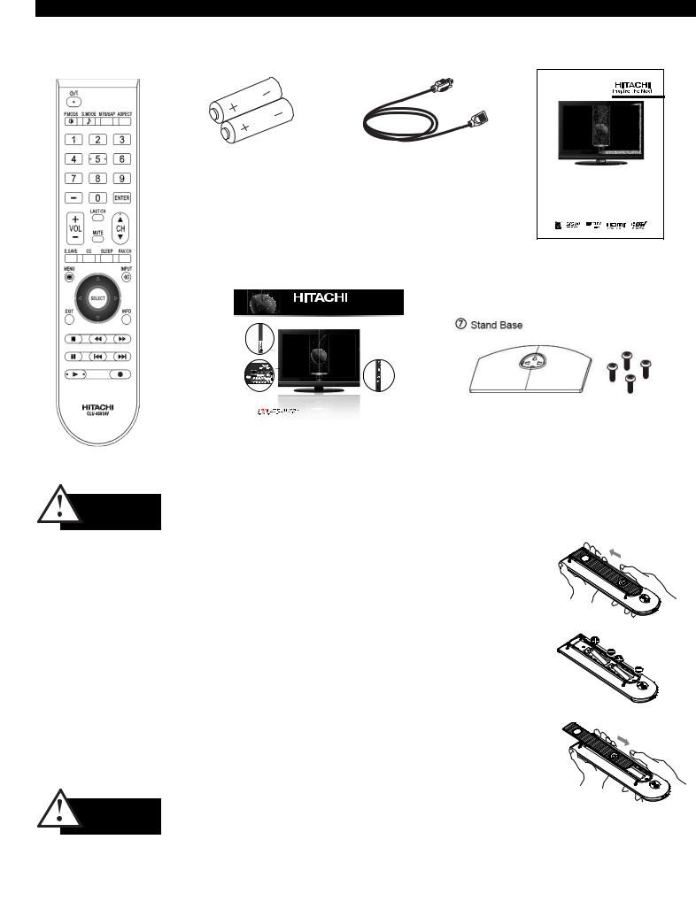
Accessories
Check to make sure you have the following accessories before disposing of the packing material.
q |
Remote Control Unit |
w |
“AA” Size |
e Power Cord |
|
CLU-4591AV |
|
Batteries (2) |
|
|
(Part No. HL02631) |
|
|
|
t Easy Graphic Guide
Easy Graphic Guid e
*Image may differ from actual product.
Side Jacks
Side
Controls
Rear Jacks
|
www.hitachi.us/tv |
1-800-Hitachi (1-800-448-2244) |
|
|
|
|
|
OPERATING GUIDE |
GUIA DE OPERACION |
GUIDE D’OPÉRATION |
|
|
IMPORTANTE: APAGAR EL TELEVISOR Y LOS |
ÍMPORTANT: ÉTEINDRE TÉLÉVISION ET TOUTES |
|
|
EQUIPOS EXTERNOS ANTES DE CONECTAR O |
AUTRES COMPOSANTES EXTERNES AVANTE DE |
|
|
DESCONECTAR LOS CABLES. |
DEBRACHER OU DE DÉBRANCHER TOUT CÂBLE. |
|
r OperatingGuide
NEED MORE INFO ON THE DTV TRANSITION? See page 34 in this Operating Guide and please visit www.dtvtransition.org
Alpha Series LCD Flat Panel HDTV
Operating Guide for L42A403 & L32A403
IMPORTANT SAFETY INSTRUCTIONS ...................................................................... |
2-5 |
FIRST TIME U SE . ..................................................................................................... |
6-17 |
THE REMOTE CONTROL ......................................................................................... |
18-21 |
ON-SCREEN D ISPLAY .......................................................................................... |
22-34 |
USEFUL I NFORMATION ........................................................................................ |
3 5-41 |
LIMITED WARRANTY .................................................................................................... |
42 |
END USER L ICENSE A GREEMENT FOR HITACHI DTV SOFTWARE ............. |
4 3-48 |
APPENDIXES ................................................................................................................. |
49 |
INDEX ............................................................................................................................. |
50 |
READ THE ENCLOSED INSTRUCTIONS CAREFULLY. KEEP THIS OPERATING GUIDE FOR FUTURE REFERENCE.
Record the model name and serial number of your LCD Television for future reference.
MODEL NAME. ____________________ SERIAL NO. ________________________
This information is located on the back and right side of the television.
Stand Screw (4)
L32A403 |
: T4x14 |
L42A403 |
: M6x10 |
|
|
For optional accessories, please access our web site at: www.hitachi.us/tv |
CAUTION |
• |
Ceiling mounting is not recommended. Mounting the panel on the ceiling does not provide adequate ventilation |
|
|
for the electronics or proper support for the front glass panel. This LCD television product is designed for a |
|
|
maximum tilting angle of 45 degrees from vertical. |
|
• |
Please see page 8 for important information related to wall mounting. |
REMOTE CONTROL BATTERY INSTALLATION AND REPLACEMENT
The remote control operates on 2 “AA” batteries.
1. Open the battery cover of the remote control by pushing and sliding it in the direction of the arrow.
2. Insert two new “AA” size batteries for the Remote Control. When replacing old batteries, push them towards the springs and lift them out.
3. Match the batteries to the (+) and (-) marks in the battery compartment.
4. Insert the bottom of the battery, the (-) side, into the battery compartment first, push towards the springs and insert the top of the battery, the (+) side, into place. Do not force the battery into the battery compartment.
5. Close the battery cover by sliding back the cover and push the cover until it clicks shut.
CAUTION |
• Do not insert batteries with ‘+’ and ‘-’ polarities reversed as this may cause the batteries to swell or rupture |
|
resulting in leakage. |
•Never mix used and new batteries in the device.
•Replace all the batteries in the device at the same time.
•Remove the batteries if the remote control is not going to be used for an extended period of time.
6

How To Install Your New Hitachi LCD Television
Take the following precautions to prevent the LCD Television from tipping over and possibly causing injury. It is important to mount the unit on a stable and flat surface.
ASSEMBLY OF THE BASE
IMPORTANT: The base of the LCD TV must be assembled prior to use.
1.Place the TV unit face down on a soft and flat surface covered by a blanket, foam, cloth, etc. to prevent any damage or scratches to the LCD TV.
2.Carefully align and insert the Base to the TV stand post.
3.Insert the screws included with the accessories to the bottom of the base and tighten the base to the stand.
Caution when moving the main unit
As this product is heavy, whenever it is moved, at least two people are required to transport it safely. Whenever the unit is moved it should be lifted forward using the top and base on both sides of the Television for stability.
When moving the Television, lift from the corners, then support the top frame as shown below.
NOTES |
• Do not block the ventilation holes of the LCD |
|
Television. Blocking the ventilation holes might |
|
cause overheating and damage. |
•In case of an abnormal symptom, unplug the AC cord and contact 800-HITACHI.
•If you purchased a wall mount bracket, please ask for professional installation. Do not try to install by yourself.
• Install the unit at a proper area where it does not expose anyone to any danger of hitting themselves (for example their hands, head or face, etc.) against the edge of the unit that could cause personal injury.
AC Cord Installation
The power cord provided with your new LCD Television needs to be installed correctly to avoid its disconnection when rotating the TV on its Table Top Stand.
Located on the back of the TV there is one plastic clamp to hold the power cord. Please follow the instructions below.
qPass the power cord through the clamp and connect it to the
TV.
w Close the clamp to fix the power cord to the TV.
eAll the cables connected to the TV will be held by this clamp.
AC Wire Clamp
USE TIME FIRST
Location
Select an area where sunlight or bright indoor illumination will not fall directly on the picture screen. If so, drapes or screens can be used to reduce the reflection.
Also, be sure that the location selected allows a free flow of air to and from the perforated back cover of the set. In order to prevent an internal temperature increase, maintain a space of 10 cm (4 inches) from the sides/back of the Television, and 30 cm (12 inches) from the top of the television to the ceiling. To avoid cabinet warping, cabinet color changes, and increased chance of set failure, do not place the TV where temperatures can become excessively hot, for example, in direct sunlight or near a heating appliance, etc.
|
30 cm (12 inches) |
10 cm |
10 cm |
(4 inches) |
(4 inches) |
Securing to a Wall
1.Using metallic wire (two locations) fasten the set to the clamping screw on the rear of the LCD TV as shown below.
2.Keep the LCD television 4 inches away from the wall, except when mounted using the wall mount bracket, and secure to the wall as shown below:
A
Wire
Wire
Wire
Screw Clamp
|
A |
|
|
32” |
4 in. |
|
|
42” |
10 cm. |
7

How To Install Your New Hitachi LCD Television
WALL MOUNTING SETUP
STEP (1) : REMOVE THE STAND BASE FROM THE LCD TELEVISION
In order to remove the stand from the TV, please put the TV set on a soft and flat surface (blanket, foam, cloth, etc.) to prevent any damage; then remove the 4 screws shown below in order to separate the TV from the Table Top Stand. Now the Stand can be separated from the TV. Useful dimensions for the WALL MOUNT assembly are in page 39 and 40.
(a)4 Screws ( (a) M4 and
(a)

 (b) (b) tapping screws) Do
(b) |
not mix please. |
|
Stand Base
STEP (2) : INSTALL THE WALL MOUNT BRACKETS ON THE LCD TELEVISION USING 4 SCREWS.
|
Screw Length (A) |
|
Screw Mounting Holes (4 places). Don't |
Insertion length (B) |
|
use the original screws (A) were in the |
|
|
TV for the Table Top Stand. The original |
|
|
screws are not long enough to properly |
|
|
secure the TV to the wall bracket. |
Spring Washer (C) |
|
|
||
|
Plane Washer (D) |
|
|
Wall Mount Bracket (E) |
|
|
Example : |
|
|
A = B+C+D+E |
|
Wall Mount Brackets |
A: 13.5~15.5 mm. |
|
|
B: 8.5~10.5 mm. |
|
|
C: 1 mm. |
|
For Wall Mount assembly; please refer to the Installation Manual of the |
D: 1 mm. |
|
E: 3 mm. |
||
Wall Mount Unit. |
||
The screw type :Thread ISO M6 (Metric |
||
|
||
|
type, do not use Standard type). |
CAUTION
Insertion length (B) of the screws must be within 8.5~10.5 mm. If the length is less than 8.5 mm, the weight can not be maintained. If the length is more than 10.5 mm, a space is created between the Wall Mount Bracket and the LCD Television. This length is very important.
STEP (3) : TIPS TO CONSIDER FOR THE LOCATION OF THE LCD TELEVISION.
|
|
|
More than |
|
|
|
|
30 cm (1'). |
|
More than |
Keep |
|||
10 cm (4"). |
||||
more than |
||||
|
|
|
2 cm (0.8") |
|
|
|
|
away from |
|
|
|
|
the wall. |
|
|
|
|
|
|
|
|
|
|
|
•• Do not block the ventilation holes. In
addition please keep a certain distance around CAUTION and make sure not to obstruct ventilation.
Blocking the ventilation holes might cause fire or defect.
•• If you purchased a Wall Mount bracket, please ask for a professional installation. Do not install by yourself.
•• This LCD unit features an advanced ventilation system configured for vertical installation. A knowledgeable and experienced professional technician can perform other mounting or installation orientations (e.g., horizontal, tilted) provided that you specifically inform the technician of the unit's specialized ventilation needs. Call 800-HITACHI for additional info and guidance.
CAUTION |
AlthoughthisLCDDisplayPanelcanbeinstalledusingavarietyofthirdpartywallmountingbrackets/devices, |
such third party brackets/devices have not been tested or approved by Hitachi for use or compatibility with |
|
|
this LCD Display Panel. Accordingly, Hitachi accepts no responsibility or liability for any injuries or property |
|
damage resulting from the use of such third party brackets/devices. Hitachi strongly advises that any |
installation of this LCD Display Panel using wall mounting brackets/devices be performed only by a qualified and experienced television installation technician who has completed a thorough evaluation of:
a)the weight-bearing strength and stability of the intended wall mount surface; and
b)the weight-bearing strength and compatibility of the intended wall mount brackets/device.
8

Side Panel Jacks & Controls
i


 r
r
u
 t
t
Only L42A403
Model.
|
w |
|
aR/C Sensor |
|
e |
y |
q |
s |
|
POWER button
This power button is for turning ON the LCD TV, in order to turn the TV On , the standby indicator must be lit red. If the indicator is off, plug the power cord into the AC wall outlet.
MENU button
This button allows you to enter the MENU, making it possible to set TV features to your preference without using the remote. This button also serves as the Return button when in the MENU system.
INPUT button
Press this button to access the INPUT menu.
VOLUME (+/-) level
Press these buttons to adjust the sound level. The volume level will be displayed on the TV screen. These buttons also serve as the cursor left and right buttons when in the Menu system.
CHANNEL selector
Press these buttons until the desired channel appears in the top right corner of the TV screen. These buttons also serve as the cursor down ( ) and up (
 ) buttons when in MENU mode.
AV 2 (SIDE) JACKS
AV2 provide composite Video and S-Video (Only for L42A403) jacks for connecting equipment with this capability, such as a DVD player, Game Console or Camcorders.
HDMI-3 & HDMI-4
Use these side HDMI inputs for AV equipment such as Set-Top-Boxes or DVD players equipped with an HDMI output connection (see page 14 for reference).
FRONT VIEW
POWER  o Indicating Lamp
USB UPGRADE SLOT
This USB slot is for future software upgrades.
POWER light indicator
To turn the TV ON, press the Power button ). A red stand-by indicator lamp located on the lower left corner of the front bezel has to be illuminated in order to turn ON the LCD TV.
Indicating |
Power |
Operating |
Lamp |
Status |
|
Lights |
OFF |
When the LCD TV is plugged |
Red |
(Stand-by) |
to the AC line. |
Lights |
ON |
TV Power is ON; picture is |
Blue |
|
shown. |
Quickly |
ON |
The TV is powering OFF. |
Blinking Red |
|
It will soon be in the Off |
|
|
(Stand-by) state. |
Slowly Blinks |
ON |
TV is in the RGB input and |
Red |
(Stand-by) |
has been without an input |
|
|
signal for 15 mins. TV will |
|
|
resume after the input signal |
|
|
is detected. |
REMOTE CONTROL sensor
Point your remote at this area when selecting channels, adjusting volume, etc.
NOTES |
• Your HITACHI LCD TV will not show any picture if |
|
there is no video input whenAV1,AV2, Component1 |
|
or 2, or HDMI 1, 2, 3 or 4 is selected. Instead a |
|
message will indicate “No Signal” and the Power |
|
Light will remain Blue until the TV is turned off or in |
|
Stand-by mode (lights red) when not in use. |
•The Remote Control can turn the TV ON/OFF as well as turning ON/OFF any compatible HDMI
CEC devices.
Headphone jack
s Use this jack to connect headphones.
USE TIME FIRST
9

Rear Panel Jacks
7
Antenna Input
To switch between Cable and Air, go to the Channels Menu option to change the signal source CABLE or AIR (see page 33).
Component: Y-PbPr and Audio Inputs
Component 1 and 2 provide Y-PbPr and Audio jacks for connecting equipment with this capability, such as a DVD player or Set Top Box.
• Your component outputs may be labeled
NOTES Y, B-Y, and R-Y. In this case, connect the components B-Y output to the TV’s Pb input
and the components R-Y output to the TV’s Pr input.
•Your component outputs may be labeled Y-CbCr. In this case, connect the component Cb output to the TV’s Pb input and the component CR output to the TV’s Pr input.
•It may be necessary to adjust TINT to obtain optimum picture quality when using the
Y-PbPr inputs (see page 24).
HDMI 1, 2 (High Definition Multimedia Interface)
ABOUT HDMI – HDMI is the next-generation, all digital
interface for consumer
electronics. HDMI enables the secure distribution of uncompressed high-definition video and multichannel audio in a single cable. Because digital television (DTV) signals remain in digital format, HDMI assures that pristine high-definition images retain the highest video quality from the source all the way to your television screen. Use the HDMI input for your AV equipment such as Set-Top-Boxes or DVD players equipped with an HDMI output connection.
RGB
RGB
6
HDMI, the HDMI logo and High-Definition Multimedia
Interface are trademarks or registered trademarks of HDMI Licensing LLC.
Digital Out (Optical Digital Audio)
This jack provides Digital Audio Output from a HDMI source or digital program channel to your audio device that is RAW and PCM compatible, such as an audio amplifier.
*Manufactured under license from Dolby NOTE Laboratories. “Dolby” and the double-D symbol
are trademarks of Dolby Laboratories
RGB and AUDIO for Personal Computers (PC)
UsetheRGB/AnalogAudioInputterminalforconnecting a PC or Laptop using a RGB cable (D-sub 15 pin) to your LCD TV. Please see page 49 for compatible resolutions.
Composite AV1 JACKS
AV1 input provides composite Video and S-Video jacks for connecting equipment with this capability, such as a DVD player, Game Console or Camcorders.
Audio Out jack
This jack provides stereo audio output from your TV to your audio device, such as an audio amplifier.
10
Quick Reference Remote Control Buttons and Functions
In addition to controlling all of the functions on your Hitachi LCD TV, the new remote control is designed to operate different types of compatible HDMI CEC DVD Players, For HDMI CEC details please see page 31.
Power On/Off
Press this button to switch the TV set On or Off standby.
Picture Mode
Picture mode can be changed each time pressed in the following sequence.
Dynamic |
|
|
Standard |
|
|
Movie |
|
||||
|
|
|
|
|
|||||||
|
|
Game |
|
|
Custom |
|
|
|
|||
|
|
|
|
|
|
|
|||||
Numeric Buttons
Press these buttons to manually enter the channel and for numeric entry when navigating through the OSD menu system.
(-) Dash/Sleep Button
Press this button to tune a digital channel. Also press to set your Sleep Timer from 5 minutes to 4 hours.
Last Channel Button
Press this button to switch between the current and the last channel viewed.
Volume Button
Press up (+) to increase or down (-) to decrease the audio level of your TV.
Energy Save Button
Press this button to set Power Consumption reduction based on three levels (Min, Med, Max).
Closed Caption (CC) Button
Press to show and change the closed caption mode.
Menu Button
Accesses the OSD menu system.
EXIT Button
Press this button to exit the OSD menu.
Cursor PAD/Select Buttons
The Cursor PAD is used to navigate through the OSD and INPUT menu system, The Select button is used to Set/Activate highlighted menu items.
CONTROL BUTTONS (DVD with CEC)
Control the functions of compatible DVD players with HDMI-CEC control.
Aspect
Press this button to change picture size.
Sound Mde
Press this button to change the sound mode.
MTS/SAP
Press to change the audio source on the programs that are showing.
Enter Button
Press this button to use as a SELECT feature.
Channel Up/Down Buttons
Changes the channels up or down.
Mute
Reduces the audio level to 0 if pressed once, and to restore audio level press it a second time or just press the volume key.
Favorite Channel Button
Press to access Favorite Channel mode.
Sleep Button
Press to set your Sleep Timer from 5 minutes to 4 hours.
Input Select
Press this button to change the input mode.
Info Button
Shows the input signal status and other information.
USE TIME FIRST
NOTES - The TV’s remote control sensor is located on the left bottom corner of the TV frame. To control TV functions, please point the remote control directly at the sensor for best results.
- The pause key “;“ on the Remote Control can be use to Freeze the picture on the screen, in case that this key is pressed by accident, please press it one more time to restore the moving picture
11

Quick Setup Guide
Perform the following steps to quickly setup your new
Hitachi LCD Television Set.
1. ANTENNA CONNECTION
Unless your LCD Television is connected to a cable TV system or |
Air/Cable |
to a centralized antenna system, a good outdoor color TV antenna |
RGB |
is recommended for best performance. However, if you are located |
|
in an exceptionally good signal area that is free from interference |
|
and multiple image ghosts, an indoor antenna may be sufficient. |
|
a). VHF (75-Ohm) antenna/CATV (Cable TV) |
Rear Panel Jack |
When using a 75-Ohm coaxial cable system, connect the CATV |
|
coaxial cable to the AIR/CABLE (75-Ohm) terminal. Or if you have |
|
an antenna, connect the coaxial cable to the same AIR/CABLE |
|
terminal. |
|
RGB
To outdoor Antenna |
|
|
|
|
|
To Antenna |
|
|
|
|
|
||
or |
|
|
|
|
|
|
|
|
|
|
|
Terminal |
|
Cable TV (CATV) |
|
|
|
|
|
|
System |
|
|
|
|
||
b). VHF (300-Ohm) antenna/UHF antenna |
|
|||||
When using a 300-Ohm twin lead from an outdoor antenna, |
||||||
connect the VHF or UHF antenna leads to screws of the VHF or |
||||||
UHF adapter. Plug the adapter into the antenna terminal on the |
||||||
TV. |
|
|||||
To Antenna
Terminal
To outdoor VHF or UHF Antenna
c). When both VHF and UHF antennas are connected
Attach an optional antenna cable mixer to the TV antenna terminal and connect the cables to the antenna mixer. Consult your dealer or service store for the antenna mixer.
|
Air/Cable |
To UHF antenna |
To outdoor antenna |
or CATV system |
Antenna Mixer
NOTE Connecting a 300-Ohm twin lead connector may cause interference. Using a 75-Ohm coaxial cable is recommended.
2. CONNECT YOUR NEW HITACHI LCD TV TO THE POWER SOURCE
a). Connect the power cord to your TV set and secure it |
c). The Indicating Lamp will light red (Standby mode) and |
with the cable tie (see page 7) . |
then light blue (image displays). |
AC Wire Clamp
Indicating
Lamp
POWER
b). Connect the power cord to the AC wall outlet .
3. POWER ON/OFF YOUR NEW HITACHI LCD TV.
Press the POWER button on the Remote Control or the POWER button on the Side Control Panel to power on/off the LCD TV.
NOTE |
If the Indicating lamp is OFF, the Power Button on |
|
the |
|
Remote Control will not operate. Please make sure |
For Stand-By
Power OFF
4. FOLLOW THE TV SETUP WIZARD INSTRUCTIONS ON NEXT PAGE.
or
12

TV Setup Wizard
Your Hitachi LCD television has a TV Setup Wizard feature which has the ability to help you easily setup the first time you turn on your TV and find the channels available in your area. Please follow the instructions below.
The First time you turn on your Hitachi LCD TV the Initial Settings screen will appear. The first step to set is the language of your TV
On screen Menu. Select the language that you prefer. Use the p and q CURSOR to select and press the SELECT button on the remote control.
Setup Wizard (1/7)
Please select language ...
English
Spanish
French
Cancel
Navigate |
SEL Select |
The second and third steps are to set the date and time. There are two options ; one for automatic setting in which you will select only the time zone in your area and the second option is a manual setup for the date and time. Use the CURSOR pad to select and change the options with the remote control.
Setup Wizard (2/7)
Please set time mode ...
Auto
Manual
Previous Cancel
Navigate |
SEL Select |
Setup Wizard (3/7)
Please select Time Zone ...
MST
PST
EST AKST
HST
Previous Cancel
Navigate |
SEL Select |
Setup Wizard (3/7)
Please enter the date and time ...
Year |
2009 |
Month |
Jan |
Date |
1 |
Time |
12:00 AM |
|
OK |
Navigate |
SEL Select |
The fourth step is designed to find broadcasting or cable channels.
There are two options, Air for an external antenna and Cable for a cable system provider in your home. Use the p and q CURSOR to select and press the SELECT button on the remote control.
Setup Wizard (4/7)
Please select TV RF tuning band ...
Air
Cable
Previous |
Cancel |
Navigate |
SEL Select |
Step 5 will start the scanning feature to find the channels available on the antenna or cable system. Press the SELECT button on the
remote control to start the channel scan.
Setup Wizard (5/7)
Please check that the RF cable is connected properly.
Start
Previous Cancel
Navigate |
SEL Select |
The sixth step is the scanning process of the channels, it shows first the scan of analog channels and then the digital channels.
The scanning process will show how many channels have been found. Please be patient while the scanning process searches for the available channels in your area. If you wish to cancel the process, press the SELECT button on the remote control to cancel the process.
|
Setup Wizard (6/7) |
|
|
Searching, please wait ... |
|
|
Searching Analog CH |
Channel 3 |
|
Analog Channels Found |
10 |
|
Digital Channels Found |
15 |
|
10% |
|
|
Cancel |
|
|
SEL Cancel |
|
NOTES |
• Once the user cancels the wizard, the wizard will |
|
|
not be shown again. |
|
•If you see the screen above and if you did not connect your Antenna cables to your TV, turn off your TV, unplug the power cord and connect your cables according to the applicable connections in the “First Time Use” section of this Operating Guide.
•After completing the TV Setup Wizard, these screens will not appear again. For updating and adding the channels available in your area refer to the New Channel Scan feature on page 33.
The last step is the completion of process, it shows a brief message and you are ready to view TV programing. This final message will be shown for a few seconds and then the first detected channel will be tuned in. You may also press EXIT on the remote control to tune to the first detected channel.
Setup Wizard (7/7)
Congratulations. TV setup is done.
EXIT Exit
USE TIME FIRST
13

Side Panel Connections
The following connection diagrams are offered as suggestions. However, you may need to modify them to accommodate your particular assortment of components and features. For best performance, video and audio cables should be made from coaxial shielded wire. There are 2 SIDE panel HDMI jacks provided as a convenience to allow you to easily connect HDMI or DVI signals from a DVD, Set-Top- Box, Video Game as shown in the following examples (When a DVI product is connected, the use of a separate audio device is necessary for audio, use an Audio Amplifier and connect to the Audio In jacks).
A) Connecting HDMI signal
SIDE INPUT PANEL |
|
|
HDMI DIGITAL |
Set-Top Box |
|
|
OUTPUT CAPABILITY |
||
|
|
|
|
|
|
|
|
HDMI OUT |
|
|
|
|
|
Home video game system |
|
[HDMI] |
|
[HDMI] |
|
B) Connecting DVI signal |
|
DVI DIGITAL |
|
|
Audio Amplifier |
|
|
|
|
AUDIO IN |
|
|
OUTPUT CAPABILITY |
DVD player |
L R |
L (White) |
|
L (White) |
|
|
|
|
||
|
|
|
OUTPUT |
|
|
|
|
L R |
Set-Top Box |
SIDE INPUT PANEL |
R (Red) |
|
R (Red) |
Home video game system |
|
|
|
|
|
|
|
|
DIGITAL OUTPUT |
|
|
[HDMI] |
DVI to HDMI Cable |
[DVI] |
|
|
|
|
||
The SIDE panel VIDEO and S-VIDEO (Only L42A403) jacks are provided as a convenience to allow you to easily connect a Camcorder, DVD, Video Game and a VCR as shown in the following examples. (When connecting an S-VIDEO device, also connect the audio output into the Side Audio Input jacks).:
SIDE INPUT PANEL |
*S-Video Input Only for L42A403 |
|
|
L (White) |
L (White) |
R (Red) |
R (Red) |
DVD player
OUTPUT
S-VIDEO L |
R |
VCR |
|
|
|
|
|
Camcorder |
VIDEO (Yellow) |
OR |
VIDEO (Yellow) |
|
|
|
|
|
|
|||
L (White) |
|
L (White) |
OUTPUT |
|
|
|
|
|
|
||
|
|
|
VIDEO |
L R |
Home video game system |
|
|
|
|
|
|
R (Red) |
|
R (Red) |
|
|
|
For monaural devices, please connect Audio signal cable into L/Mono input jack .
NOTES • Completely insert connection cord plugs when connecting to side panel jacks. If you do not, the played back picture may be abnormal.
•Cable plugs are often color-coded. Match colors of plugs and terminals, i.e. connect red to red, white to white, etc.
•When making video connections, connect S-Video only or Video only. If both are connected, S-Video takes priority.
The exact arrangement you use to connect the VCR, Camcorder, DVD player, or HDTV Set-Top-Box to your LCD TV is dependent on the model and features of each component. Check the operating guide of each component for the location of video and audio inputs and outputs.
Before Operating External Video Sources
Connect an external source to one of the INPUT terminals, then press the INPUT button to show the Inputs List. Use the CURSORS ( and
) to select the Input of your choice. Then press the SELECT button to confirm your choice (see page 19).
 +
+  +
+
|
Input List |
|
|
0. TV |
0. TV |
1.AV1
2.AV2
3.Component1
4.Component2
5.RGB
6.HDMI 1
7.HDMI 2
8.HDMI 3
9.HDMI 4
Example: Selecting the TV (Air/Cable) Input and highlight “0:TV”.
14 |
Move SEL Select |
|

Rear Panel Connections |
|
|
|
|
|
|
|
|
|
|
|||
Outside antenna |
|
|
|
|
|
|
|
|
|
|
|
|
FIRST |
or |
|
|
|
|
|
|
|
|
|
|
HDMI |
|
|
Cable TV coaxial cable |
|
|
|
|
|
|
|
|
|
|
|
||
|
|
|
|
|
|
|
|
|
|
|
|
|
|
|
|
|
|
|
|
|
|
|
|
|
|
DIGITAL OUTPUT |
TIME |
splitter |
|
|
|
|
|
|
|
|
|
|
to |
|
|
2-Way |
|
|
|
|
|
|
|
|
|
|
AUDIO OUT |
|
|
signal |
|
|
|
|
|
|
|
|
|
|
DVI |
|
|
|
|
|
|
|
|
|
|
|
|
|
|
|
|
|
VCR |
|
|
|
|
|
|
|
|
|
|
HDMI DIGITAL |
USE |
ANT |
|
|
|
|
|
|
|
|
|
|
|
||
IN |
V |
L |
R |
|
|
|
|
|
|
|
|
OUTPUT CAPABILITY |
|
|
|
|
|
|
|
|
|
|
|
||||
|
|
|
|
|
|
|
|
|
|
|
RGB |
|
|
|
|
|
|
|
|
|
|
|
|
|
RGB |
|
|
|
|
|
|
|
|
|
|
|
|
|
|
HDMI |
|
|
|
|
|
|
|
|
|
|
|
|
|
to |
|
|
|
|
|
|
|
|
|
|
|
|
|
HDMI |
|
|
|
|
|
|
|
|
|
|
|
|
|
HDMI OUTPUT |
|
|
|
|
|
|
|
|
|
|
|
|
|
DIGITAL |
|
|
|
|
|
|
|
|
|
|
|
|
RGB |
OUTPUT CAPABILITY |
|
|
|
|
|
|
|
|
|
|
|
|
|
|
|
|
|
|
|
|
OUTPUT |
|
|
|
OUTPUT |
|
|
|
|
|
|
|
Y |
PB/CB |
PR/CR |
L |
R |
S-Video |
Video |
L |
R |
|
|
|
|
|
OPTICAL |
|
|
|
|
|
|
|
|
|
|
|
|
|
IN |
|
|
|
|
|
|
|
|
|
|
|
|
|
|
|
|
|
|
|
|
|
Personal Computer |
|
|
|
STEREO SYSTEM |
HDTV SET-TOP BOX |
DVD PLAYER |
|
DVD PLAYER |
VIDEO GAME |
|
|
AMPLIFIER |
||
|
with Component |
with Composite |
|
|
|
||
NOTE |
Cables are not included. |
Output capability |
video capability |
|
|
TIPS ON REAR PANEL CONNECTIONS
♦♦ COMPONENT Y-PbPr (COMPONENT 1 & 2) or HDMI (1 & 2) connections are provided for high performance DVD players, VCRs etc. that have this feature. Use these connections in place of the standard video connection if your device has this feature.
♦♦ If your device has only one audio output (mono sound), connect it to the left audio jack on (L) the Rear Panel.
♦♦ Refer to the operating guide of your other electronic equipment for additional information on connecting your hook-up cables. ♦♦ Connect only 1 component (VCR, DVD player, camcorder, etc.) to each input jack.
♦♦ Your component outputs may be labeled Y, B-Y, and R-Y. In this case, connect the components B-Y output to the TV’s Pb input and the components R-Y output to the TV’s Pr input.
♦♦ Your component outputs may be labeled Y-CbCr. In this case, connect the components Cb output to the TV’s Pb input and the components Cr output to the TV’s Pr input.
♦♦ It may be necessary to adjust TINT to obtain optimum picture quality when using the Y-PbPr inputs. (See page 24). ♦♦ When using a HDMI input from a Set-Top-Box, it is recommended to use a 1080p, 1080i or 720p input signal.
♦♦ When the HDMI input is a 1080p signal, it is recommended that the length of the cable should be less than 5 meters.
NOTES • Completely insert all connection cord plugs when connecting to rear panel jacks. The picture and sound that is played back will be abnormal if the connection is loose.
• Cable plugs are often color-coded. Match colors of plugs and terminals, i.e. connect red to red, white to white, etc.
Connecting a Personal Computer PC .
Use the RGB PC connection terminal and the Analog 


 Audio Input terminals to connect the PC.

1. Connect the RGB (D-sub 15 Pin) and AUDIO |
|
cable from the RGB and AUDIO OUT jack of the |
RGB |
PC to the RGB and AUDIO jack, as shown on the |
|
Rear Panel on the right. |
|
2. Press the INPUT button, then select RGB from the INPUTS menu to view the signal from the PC.
IN |
OUT |
[PC sample] |
|
|
(Audio) or
RGB
(D-sub 15 Pin)
15

Rear Panel Connections
CONNECTING A VIDEO AND MONAURAL AUDIO SOURCE TO AV 1.
1.Connect the VIDEO and AUDIO cable from the VIDEO and AUDIO OUT jack of the VCR to the AV1 (VIDEO) and L(AUDIO) jack, as shown on the Rear Panel on the right
2.Press the INPUT button, then select AV1 from the INPUTS menu to view the program from the VCR.
3.Select Audio menu, set Sound mode to “Custom”, and set “SRS Trusurround HD” to “On”.
CONNECTING A VIDEO AND STEREO AUDIO SOURCE TO AV1.
1.Connect the VIDEO and AUDIO cables from the VIDEO OUT and AUDIO OUT jacks of the VCR to the AV1 (VIDEO)jacks. A VCR connection to Rear Panel AV1 example is shown on the right.
2.Press the INPUT button, then select AV1 from the INPUTS menu to view the program from the VCR.
TV REAR PANEL
VCR
RGB
RGB
OUTPUT
AUDIO VIDEO
(White) |
(Yellow) |
TV REAR PANEL
VCR
|
OUTPUT |
|
VIDEO |
L |
R |
(Yellow) |
(White) |
(Red) |
CONNECTING A COMPONENT AND STEREO AUDIO |
TV REAR PANEL |
|
SOURCE TO COMPONENT 1 or 2: YPbPr |
||
|
1. Connect the Y, Pb/Cb, Pr/Cr and AUDIO cables from the Y, Pb/Cb, Pr/Cr OUT and AUDIO OUT jacks of the DVD PLAYER or HDTV Set-Top-Box to the COMPONENT 1 or 2 YPbPr and AUDIO jacks. A DVD connection to Rear Panel COMPONENT 2 example is shown on the right.
2. Press the INPUT button, then select COMPONENT 1 or 2 from the INPUTS menu to view the program from the DVD player or HDTV Set-Top Box.
DVD Player/ Recorder
|
|
Output |
|
|
|
|
L |
R |
Y |
PB |
PR |
White |
Red |
Green |
Blue |
|
Red |
NOTES |
• Completely insert the connection cord plugs when connecting to rear panel jacks. The picture and sound that is played |
|
back will be abnormal if the connection is loose. |
•Cable plugs are often color-coded. Match colors of plugs and terminals, i.e. connect red to red, white to white, etc.
•To return to the last channel viewed, select “0.TV” from the INPUTS menu.
16
 Loading...