


L100DN-004NFU2
Hitachi L100DN-004NFU2, L100DN-002NFE2, L100DN-005NFE2, L100DN-004HFE2, L100DN-004HFU2 Read This First Manual
...
L100DN
™
DeviceNet
Series Inverters
Addendum to L100 Series
Inverter Instruction Manual
In This Addendum.... page
— Getting Started ................................................. 3
— Inverter Mounting and Installation .................... 9
— Configuring Drive Parameters........................ 26
— Operations and Monitoring............................. 31
— Network Control and Monitoring..................... 39
— Troubleshooting and Maintenance ................. 70
In the Appendices:
— DeviceNet Object Lists................................... 71
— Network Register Map.................................... 78
— Drive Parameter Settings Tables.................... 88
— Restoring Factory Default Settings ................ 94
READ THIS FIRST!
Addendum Number: NB642X
Addendum for Manual: NB576X

2
Revisions
Revision History Table
No. Revision Comments Date of Issue
Initial Release of Addendum NB642X Jan. 2003 NB642X
Addendum
No.
DeviceNet™ is a trademark of Open DeviceNet Vendor Association, Inc.

Getting Started
This section provides specification details for L100DN DeviceNet™ Series inverters
corresponding to Chapter 1, “Getting Started,” in the L100 Inverter Instruction Manual.
Main Features
Congratulations on your purchase of a Hitachi
L100DN DeviceNet Series inverter! Like the
standard L100 Series inverters, this inverter
drive features state-of-the-art circuitry and
components, exceptionally small footprint,
and high performance. The Hitachi L100DN
product line includes all the horsepower and
power input versions, but each inverter can
also connect to a DeviceNet network for
control and monitoring. The main features are:
• 200V and 400V Class inverters
• UL or CE version available
L100DN Inverter
3
• Convenient keypad for parameter settings
• Built-in DeviceNet network interface to
allow control and monitoring via a
DeviceNet network
• Sixteen programmable speed levels
• Three-wire control interface
• Up/Down electronic motorized speed pot function
• Two-step acceleration and deceleration curves
The design in Hitachi inverters overcomes many of the traditional trade-offs between
speed, torque and efficiency. The performance characteristics are:
• Output frequency range from 0.5 to 360 Hz
• Continuous operation at 100% torque within a 1:10 speed range (6/60 Hz / 5/50 Hz)
without motor derating
Model L100DN–002NFU2

4
Getting Started
Comparison Summary, Standard vs. DeviceNet Series
The Hitachi L100DN DeviceNet Series inverters generally have the same motor control
capability as the standard L100 inverters. However, a few important differences do exist.
The addition of DeviceNet network connectivity to Hitachi inverters is accompanied by
some changes to the available parameters, functions, front panel keypad, and intelligent
terminals. Together, these changes provide a complete inverter solution with DeviceNet
network capability, while removing some features that are generally unused in
networked applications.
Feature L100 (standard) L100DN (DeviceNet)
Front panel speed control Potentiometer, output freq. —
Front panel LEDs for
networking
Front panel door Half door for programming keys
and control terminals
Analog input terminals [H], [O], [OI], [L] —
PWM output terminal [FM] —
Intelligent input terminals [1], [2], [3], [4], [5] [1], [2], [3] only
Intelligent input functions Includes [AT] Includes [STA], [STP], [F/R],
Intelligent output terminals [11], [12], [AL0] to [AL2] [11], [12] only
Intelligent output functions Includes [OD] —
Digital operator configuration B_89 —
Network connector on front
panel
Network connector for cable — DeviceNet on removable Phoenix
DeviceNet network settings — P_41to P_49
Frequency source selection A_01 (selects potentiometer,
RS422 or RJ11 modular DeviceNet on Phoenix
control terminal, or F_01)
— MS – Module Status LED,
NS – Network Status LED
—
[UP], [DWN], [DNT], [OPE]
5-terminal conn., male
5-terminal conn., female
A_01 does not exist, so freq.
source is always F_01 or the
DeviceNet network host
Analog input settings A_11 to A_16, B_81, C_81, C_82 —
Analog output settings C_23 —
PID control settings D_04, A_71 to A_76, C_44 —
Intelligent input terminal
settings for [4] to [6]
Intelligent output terminal
settings for [AL0] to [AL2]
TIP: When using the standard L100 Series manual with your L100DN DeviceNet series
inverter, refer to this page for a summary of the exceptions to that manual. Also note that
your L100DN inverter comes with its own Quick Reference Guide (QRG).
C_04, C_05, C_06,
C_14, C_15, C_16
C_24, C_33 —
—

Inverter Specifications Label
The Hitachi L100DN Series inverters have product labels located on the right side of the
housing, as pictured below. Be sure to verify that the specifications on the labels match
your power source, motor, and application safety requirements.
Specifications label
Inverter model number
L100DN Inverter
5
Regulatory agency approvals
Motor capacity for this model
Power Input Rating:
frequency, voltage, phase, current
Output Rating:
Frequency, voltage, current
Manufacturing codes:
Lot number, date, etc.
Model Number Convention
The model number for a specific inverter contains useful information about its operating
characteristics. Refer to the model number legend below:
L100DN 002 H F U
Series name
2
Version number (_, 1, 2, ...)
Restricted distribution:
E=Europe, U=USA
Configuration type
F = with digital operator (keypad)
Input voltage:
N = single or three-phase 200V class
H = three-phase 400V class
L = three phase only, 200V class
Applicable motor capacity in kW
002 = 0.2 kW
004 = 0.4 kW
005 = 0.55 kW
007 = 0.75 kW
011 = 1.1 kW
015 = 1.5 kW
022 = 2.2 kW
030 = 3.0 kW
037 = 3.7 kW
040 = 4.0 kW
055 = 5.5 kW
075 = 7.5 kW

6
Getting Started
DeviceNet Networking Overview
Hitachi L100DN DeviceNet Series inverters are optimized for use on a DeviceNet
network. The inverter can respond to commands such as Run/Stop from a network host
device, for example. L100DN inverters can also drive a motor in stand-alone mode,
without a network connection. In that case, you use the inverter’s keypad or input terminals for Run/Stop commands. However, this addendum will use stand-alone operation
only for initial powerup tests of your L100DN inverter during installation. After the
installation material, the addendum covers network operation in detail.
The diagram below shows L100DN inverters connected to a DeviceNet network. Each
connection is called a node, and the L100DN connects to the network via the 5-pin,
color-coded Phoenix connector on the front panel as shown.
Network host computer L100DN inverter L100DN inverter
DeviceNet network
A DeviceNet network supports up to 64 devices, each with their own node address. One
device will be the network master; all other device(s) will be network slaves. The
L100DN inverter will operate as a network slave, as the network master (also called host
computer) will send commands to the slaves.
A factory network such as DeviceNet allows you to integrate devices of many different
types, even from various manufacturers, all into an integrated control system. A common
application that uses DeviceNet is a conveyor line. Typical devices on the network
include a PLC (programmable logic controller) or host computer (such as a PC), inverter
drives to run motors, proximity sensors, limit switches, diverter actuators, barcode
scanners, label printers, and other packaging or shipping devices. Note that Hitachi also
provides the L100DN DeviceNet Series inverters, which can also reside on the
DeviceNet network.
For detailed DeviceNet network configuration instructions, see “Network Control and
Monitoring” on page 39.

L100DN Inverter
General Specifications
L100DN DeviceNet Series inverters have the same electrical characteristics for driving
the motor as the standard L100 inverters. So, refer to the L100 instruction manual for the
electrical specifications tables and derating curves. The general specifications in this
section will be similar to the those for the standard L100 inverters, but they reflect the
differences given in “Comparison Summary, Standard vs. DeviceNet Series” on page 4.
The following table applies to all L100DN DeviceNet Series inverters.
Item General Specifications
Protective housing *1 IP20
Control method Sine wave pulse-width modulation (PWM) control
Output frequency range *2 0.5 to 360 Hz
Frequency accuracy Digital command: 0.01% of the maximum frequency
Frequency setting resolution Digital: 0.1 Hz; DeviceNet: 0.01 Hz
Volt./Freq. characteristic V/f optionally variable, V/f control (constant torque, reduced torque)
Overload current rating 150%, 60 seconds
7
Acceleration/deceleration time 0.1 to 3000 sec., (linear accel/decel), second accel/decel setting
available
Input
signal
Output
signal
Other functions AVR function, curved accel/decel profile, upper and lower limiters,
Freq.
setting
FWD/
REV
Run
Intelligent input
terminal
Intelligent output
terminal
Operator panel Up and Down keys / Value settings
Network DeviceNet polled I/O – continuous update of output frequency
Operator panel Run/Stop (Forward/Reverse run change by command)
External signal Forward run/stop, Reverse run/stop (on intelligent terminals)
Network Forward run/stop, Reverse run/stop
FW (forward run command), RV (reverse run command), CF1~CF4
(multi-stage speed setting), JG (jog command), 2CH (2-stage accel./
decel. command), FRS (free run stop command), EXT (external
trip), USP (startup function), SFT (soft lock), RS (reset), PTC
(thermal protection), STA (start, 3-wire interface), STP (stop, 3-wire
interface), F/R (FW/RV, 3-wire interface), DNT (DeviceNet select),
UP (remote control accel.), DWN (remote control decel.), OPE
(Force Operation from Digital Operator)
RUN (run status signal), FA1,2 (frequency arrival signal), OL
(overload advance notice signal), AL (alarm signal)
16-stage speed profile, fine adjustment of start frequency, carrier
frequency change (0.5 to 16 kHz) frequency jump, gain and bias
setting, process jogging, electronic thermal level adjustment, retry
function, trip history monitor
Protective function Over-current, over-voltage, under-voltage, overload, extreme high/
low temperature, CPU error, memory error, ground fault detection at
startup, internal communication error, electronic thermal, DeviceNet
comm. error

8
Getting Started
Item General Specifications
Operating
Environ
ment
Coating color Light purple, cooling fins in base color of aluminum
Options Braking unit, braking resistor, AC reactor, DC reactor, noise filter,
Temperature Operating (ambient): -10 to 50°C (*3) / Storage: -25 to 70°C (*4)
Humidity 20 to 90% humidity (non-condensing)
Vibration *5
Location Altitude 1,000 m or less, indoors (no corrosive gasses or dust)
5.9 m/s
DIN rail mounting
2
(0.6G), 10 to 55 Hz
Note 1: The protection method conforms to JEM 1030.
Note 2: To operate the motor beyond 50/60 Hz, consult the motor manufacturer for
the maximum allowable rotation speed.
Note 3: If operating the inverter in an ambient temperature of 40–50
° C, reduce the
carrier frequency to 2.1 kHz, derate the output current by 80%, and remove
the top housing cover. Note that removing the top cover will nullify the
NEMA rating for the inverter housing.
Note 4: The storage temperature refers to the short-term temperature during transport.
Note 5: Conforms to the test method specified in JIS C0911 (1984). For the model
types excluded in the standard specifications, contact your Hitachi sales representative.

Inverter Mounting and Installation
This section describes the L100 Series installation corresponding to Chapter 2, “Inverter
Mounting and Installation,” in the L100 Inverter Instruction Manual.
Orientation to Inverter Features
Please take a few moments to unpack your new L100DN inverter and do these steps:
1. Look for any damage that may have occurred during shipping.
2. Verify the contents of the box include:
a. One L100DN inverter
b. One Addendum for L100DN inverter (read this addendum first!)
c. One L100 Instruction Manual
d. One L100DN Quick Reference Guide
e. One packet of desiccant—discard (not for human consumption)
3. Inspect the specifications label on the side of the inverter. Make sure it matches the
product part number you ordered.
L100DN Inverter
9
The L100DN DeviceNet Series inverters vary in size according to the current output
rating and motor size for each model number. All feature the same basic keypad and
connector interface for consistent ease of use. The inverter construction has a heat sink at
the back of the housing. The larger models include a fan(s) to enhance heat sink performance. The mounting holes are pre-drilled in the heat sink for your convenience. Never
touch the heat sink during or just after operation; it can be very hot.
The electronics housing and front panel are built onto the front of the heat sink. The front
panel has two levels of physical access designed for convenience and safety:
• First-level access – for basic use of inverter, editing parameters, and wiring control
signals or network connection (power ON)
• Second-level access – for wiring the inverter power supply or motor (power OFF)
1. First-level Access – View the unit just as it
came from the box as shown. The four-digit
display can show a variety of performance
parameters. LEDs indicate whether the
display units are Hertz or Amperes. Other
LEDs indicate AC Power (external), Run/
Stop Mode, Program/Monitor Mode,
Module Status, and Network status.
Membrane keys Run and Stop/Reset
control motor operation. And, you can
access the two chassis GND screws on the
metal tab at the bottom of the inverter.

10
Inverter Mounting and Installation
The FUNC., , , and STR keys allow an operator to access and change the
2
1
inverter’s functions and parameter values. The top 8-position connector provides the
interface for logic-level control signals. The bottom 5-position connector is the
DeviceNet interface. It comes with a removable connector for connecting to a DeviceNet
cable. These signals are generally low-voltage in nature and are appropriate for firstlevel access.
Controls for mode
and parameter
changes
Control signal
connector
DeviceNet
connector
2. Second-level access – First, ensure no
power source of any kind is connected to
the inverter. If power has been connected,
wait five minutes after powerdown and
verify the Power LED is OFF to proceed.
Then locate the recessed retention screw
on the left side main front panel (it is
along the left hinge area on some models,
or behind the first access door on others).
Use a small screwdriver (Regular or
Phillips) to loosen the screw. Swing the
door around to the right to reveal the
internal components of the drive. The twolevel tiered 12-position terminal block
Auxiliary network power
connector
Retention screw
accepts wires for the power input and
wires to the motor.
NOTE: The 3-terminal connector located on the circuit board behind the hinged front
door can be used to connect DeviceNet network power. See “Step 2 – Connect Network
Devices” on page 43 for more information.

Notice the housing partition that lifts out to
allow full access to the terminals for wiring
as shown. Never operate the inverter drive
with the partition removed or the full access
door opened.
Never directly touch any terminal or circuit
component. This protects you from touching
a n unexpected live circuit, and it protects the
inverter from electrostatic discharge (ESD).
The power and motor connector terminals are
accessible with the removal of the housing
partition. The input power and motor connections use the lower row of terminals. The
upper row is for connecting dynamic braking
components.
L100DN Inverter
11
Housing partition
Power and motor
connector terminals

12
Inverter Mounting and Installation
System Description and Basic Installation
The Basic System Description and Step-by-Step Basic Installation sections in Chapter 2
of the standard L100 manual (included) will show you how to choose a mounting
location and wire the inverter’s power input and motor output terminals. Wire gauge,
terminal torque specifications, fuse or breaker size, and many important Warning and
Caution messages are included. So, all of the information you need to physically install
your L100DN DeviceNet inverter is in the standard manual—with the exception of the
dimension drawings, which follow below.
NOTE: After doing the basic installation (physical mounting and power wiring) per the
instructions in Chapter 2 of the L100 manual, be sure to return to this addendum for the
Powerup Test and Front Panel Keypad orientation.
Check Inverter Dimensions – Locate the applicable drawing on the following pages for
your inverter.
Dimensions are given in millimeters (inches) format.
L100DN
MODEL H mm (in.)
-002NFE2
-002NFU2
-004NFE2
-004NFU2
-005NFE2
93 (3.66)
93 (3.66)
107 (4.21)
107 (4.21)
107 (4.21)
110(4.33)
67(2.64)
5(0.20)
80(3.15)
120(4.72)
Ground Terminal
10(0.39)
H=93(3.66)
H=107(4.21)
2.5(0.10)

Dimensional drawings, continued...
MODEL
L100DN
-004HFE2
-004HFU2
-007NFE2
-007NFU2
-011NFE2
118(4.65)
5(0.20) 5(0.20)
10(0.39)
L100DN Inverter
13
98(3.86)
130(5.12)
Ground Terminal
110(4.33)
L100DN
-007HFE2 (no fan)
-007HFU2 (no fan)
-015HFE2
-015HFU2
-022HFE2
-022HFU2
118(4.65)
5(0.20) 5(0.20)
129(5.08)
2.5(0.10)
98(3.86)
130(5.12)
110(4.33)
Ground Terminal
156(6.14)
6(6.24)

14
Inverter Mounting and Installation
Dimensional drawings, continued...
140(5.51)
128(5.04)
L100DN
-015NFE2
-015NFU2
168(6.61)
10(0.39)
180(7.09)
5(0.20)
Ground Terminal
153(6.02)
6(0.24)
140(5.51)
128(5.04)
L100DN
-022NFE2
-022NFU2
-037LFU2
-030HFE2
-040HFE2
-040HFU2
168(6.61)
180(7.09)164(6.46)
5(0.20)5(0.20)
6(0.24)

Dimensional drawings, continued...
182(7.17)
160(6.30)
L100DN
1(0.04)
-055LFU2
-075LFU2
-055HFE2
-055HFU2
-075HFE2
-075HFU2
L100DN Inverter
15
236(9.29)
257(10.12)
7(0.28)7(0.28)
Ground Terminal
170(6.69)
6(0.24)

16
Inverter Mounting and Installation
Powerup Test Overview
After wiring the inverter and motor, you’re ready to do a powerup test. The procedure
that follows is designed for the first-time use of the drive. Please verify the following
conditions before conducting the powerup test:
• You have followed all the steps in this chapter up to this step.
• The inverter is new, and is securely mounted to a non-flammable vertical surface
• The inverter is connected to a power source and motor.
• No additional wiring of inverter connectors or terminals has been done.
• The power supply is reliable, and the motor is a known working unit, and the motor
nameplate ratings match the inverter ratings.
• The motor is securely mounted, and is not connected to any load.
Goals for the Powerup test
If there are any exceptions to the above conditions at this step, please take a moment to
take any measures necessary to reach this basic starting point. The specific goals of this
powerup test are:
1. Verify that the wiring to the power supply and motor is correct.
2. Demonstrate that the inverter and motor are generally compatible.
3. Give a brief introduction to the use of the built-in operator keypad.
The powerup test gives you an important starting point to ensure a safe and successful
application of the Hitachi inverter. We highly recommend performing this test before
proceeding to the other chapters in this manual.
Pre-test and Operational Precautions
The following instructions apply to the powerup test, or to any time the inverter is
powered and operating. Please study the following instructions and messages before
proceeding with the powerup test.
1. The power supply must have fusing suitable for the load. Check the fuse size chart
presented in the inverter manual in Chapter 2, if necessary.
2. Be sure you have access to a disconnect switch for the drive input power if necessary.
However, do not turn OFF power during inverter operation unless it is an emergency.
CAUTION: The heat sink fins will have a high temperature. Be careful not to touch
them. Otherwise, there is the danger of getting burned.
CAUTION: The operation of the inverter can be easily changed from low speed to high
speed. Be sure to check the capability and limitations of the motor and machine before
operating the inverter. Otherwise, there is the danger of injury.

CAUTION: If you operate a motor at a frequency higher than the inverter standard
default setting (50Hz/60Hz), be sure to check the motor and machine specifications with
the respective manufacturer. Only operate the motor at elevated frequencies after getting
their approval. Otherwise, there is the danger of equipment damage and/or injury.
CAUTION: Check the following before and during the powerup test. Otherwise, there is
the danger of equipment damage.
• Is the shorting bar between the [+1] and [+] terminals installed? DO NOT power or
operate the inverter if the jumper is removed.
• Is the direction of the motor rotation correct?
• Did the inverter trip during acceleration or deceleration?
• Were the RPM and frequency meter readings as expected?
• Were there any abnormal motor vibrations or noise?
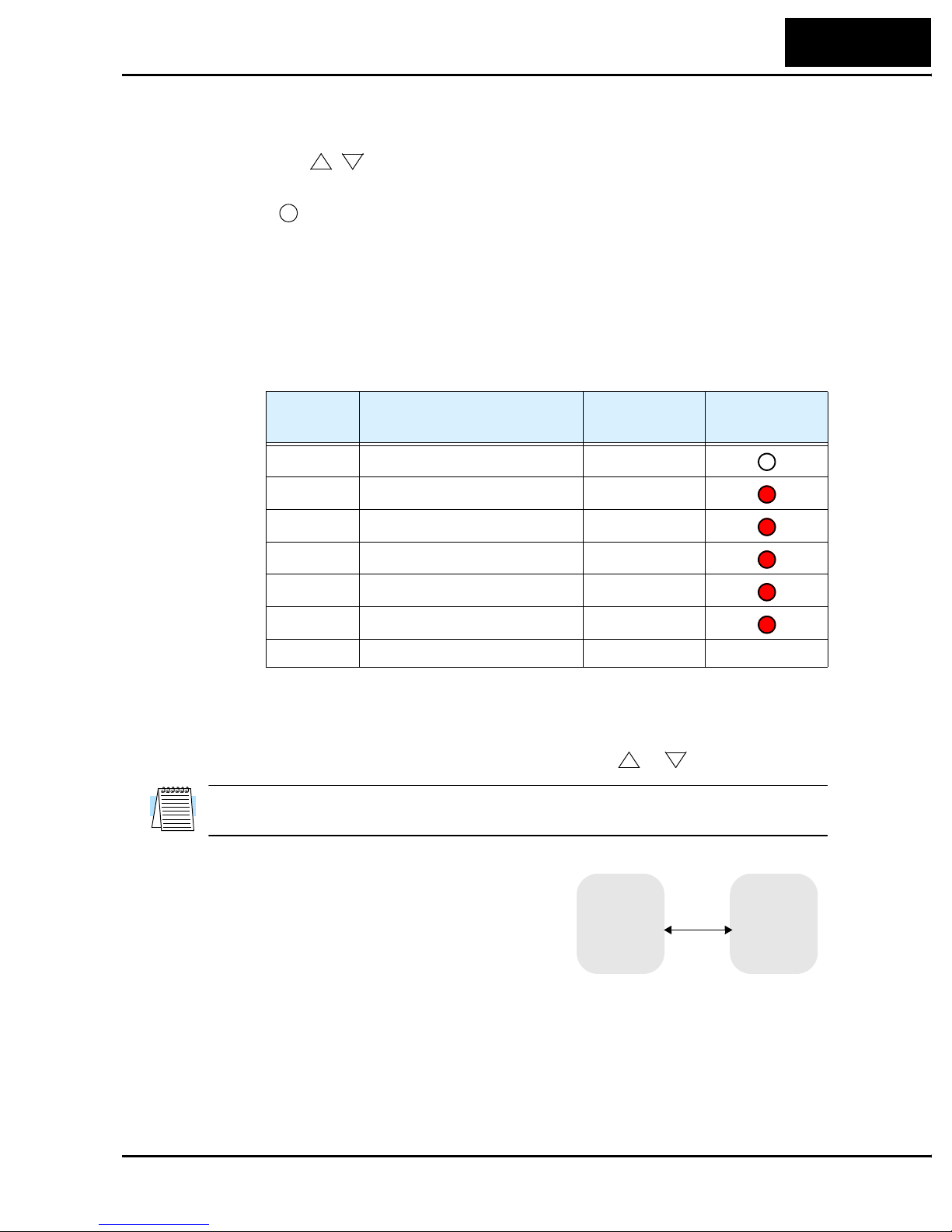
Powering the Inverter
If you have followed all the steps, cautions and warnings up to this point, you’re ready to
apply power. After doing so, the following events should occur:
L100DN Inverter
17
• The POWER LED will illuminate.
• The numeric (7-segment) LEDs will display a test pattern, then stop at 0.0.
• The Hz LED will be ON. (This assumes the inverter is in Monitor Mode and is
displaying D_01, the output frequency.)
• The MS (Module Status) and NS (Network Status) LEDs will exhibit a test pattern;
each LED will briefly show green, then red. The ending state of powerup pattern is:
MS = Green; NS = OFF.
If the motor starts running unexpectedly or any other problem occurs, press the STOP
key. Only if necessary should you remove power to the inverter as a remedy.
NOTE: If the inverter has been previously powered and programmed, the LEDs (other
than the POWER LED) may illuminate differently than as indicated above. If necessary,
you can initialize all parameters to the factory default settings. See “Restoring Factory
Default Settings” on page 94 or refer to the L100DN Quick Reference Guide.

18
Inverter Mounting and Installation
Using the Front Panel Keypad
Please take a moment to familiarize yourself with the keypad layout shown in the figure
below. These are the visible controls and indicators when the front panel door is closed.
The display is used in programming the inverter’s parameters, as well as monitoring
specific parameter values during operation. Many functions are applicable only during
the initial installation, while others are more useful for maintenance or monitoring.
Parameter Display
Run/Stop LED
Program/Monitor LED
Run Key Enable LED
Run Key
RUN
PRG
RUN
FUNC.
HITACHI
50.0
STOP
RESET
2
1
STR
POWER
Hz
A
MS
NS
Power LED
Display Units
Hertz / Amperes LEDs
Module Status LED
Network Status LED
Stop/Reset Key
Function
Key
Up/Down
Keys
Store
Key
• Run/Stop LED - ON when the inverter output is ON and the motor is developing
torque (Run Mode), and OFF when the inverter output is OFF (Stop Mode).
• Program/Monitor LED - This LED is ON when the inverter is ready for parameter
editing (Program Mode). It is OFF when the parameter display is monitoring data
(Monitor Mode).
• Run Key Enable LED - is ON when the inverter is ready to respond to the Run key,
OFF when the Run key is disabled.
• Run Key - Press this key to run the motor (the Run Enable LED must be ON first).
Parameter F_04, Keypad Run Key Routing, determines whether the Run key generates
a Run FWD or Run REV command.
• Stop/Reset Key - Press this key to stop the motor when it is running (uses the
programmed deceleration rate). This key will also reset an alarm that has tripped.
• Module Status LED - ON (green) when the inverter has power. The Module Status
LED may also be flashing and/or red in color. For a description of all LED states and
their meanings, see the table in “Step 6 – Monitor Test – Verify Network Host Can
Monitor Inverter” on page 51.
• Network Status LED - ON (green) when the inverter is connected to the network.
The Network Status LED may also be flashing and/or red in color. For a description of
all LED states and their meanings, see the table in “Step 6 – Monitor Test – Verify
Network Host Can Monitor Inverter” on page 51.
• Parameter Display - A 4-digit, 7-segment display for parameters and function codes.
• Display Units, Hertz/Amperes - One of these LEDs will be ON to indicate the units
associated with the parameter display.
• Power LED - This LED is ON when the power input to the inverter is ON.
L100DN Inverter
• Function Key - This key is used to navigate through the lists of parameters and
functions for setting and monitoring parameter values.
19
• Up/Down ( , ) Keys - Use these keys alternately to move up or down the lists of
2
1
parameter and functions shown in the display, and increment/decrement values.
• Store ( ) Key - When the unit is in Program Mode and you have edited a parameter
STR
value, press the Store key to write the new value to the EEPROM.
Keys, Modes, and Parameters
Purpose of the keypad is to provide a way to change modes and parameters. The term
function applies to both monitoring modes and parameters. These are all accessible
through function codes that are primarily 3-character codes. The various functions are
separated into related groups identifiable by the left-most character, as the table shows.
Function
Group
“D” Monitoring functions Monitor
“F” Main profile parameters Program
“A” Standard functions Program
“B” Fine tuning functions Program
“C” Intelligent terminal functions Program
Type (Category) of Function Mode to Access
PGM LED
Indicator
“P” DeviceNet network settings Program
“E” Error codes — —
For example, function “A_04” is the base frequency setting for the motor, typically
50 Hz or 60 Hz. To edit the parameter, the inverter must be in Program Mode (PGM
LED will be ON). You use the front panel keys to first select the function code “A_04.”
After displaying the value for “A_04,” use the Up/Down ( or ) keys to edit it.
1
2
NOTE: The inverter 7-segment display shows lower case “b” and “d,” meaning the same
as the upper case letters “B” and “D” used in this manual (for uniformity “A to F”).
The inverter automatically switches into Monitor
Mode when you access “D” Group functions. It
switches into Program Mode when you access any
other group, because they all have editable parameters. Error codes use the “E” Group, and appear
automatically when a fault event occurs. Refer to
MONITOR PROGRAM
“A” Group
“B” Group
“D” Group
“C” Group
“P” Group
“F” Group
Chapter 6 in the L100 inverter instruction manual
for error code details.

20
Inverter Mounting and Installation
Keypad Navigational Map
The L100DN Series inverter drives have many programmable functions and parameters.
Chapter 3 in the manual will cover these in detail, but you need to access just a few items
to perform the powerup test. The menu structure makes use of function codes and
parameter codes to allow programming and monitoring with only a 4-digit display and a
few keys and LEDs. So, it is important to become familiar with the basic navigational
map of parameters and functions in the diagram below.
Program ModeMonitor Mode
PRG LED=ONPRG LED=OFF
Display Data
000.0
1
FUNC.
d 16
1
2
d 01
1
2
P - -
1
2
C - -
1
b --
1
2
2
A - -
1
2
powerdown
Select
Function
or Group
FUNC.
Select Parameter
1
P 4 9
1
2
P 4 1
1
2
C 4 3
1
2
C 0 1
1
b 88
1
b 01
1
2
2
2
A 9 8
1
2
Edit Parameter
Store as
powerup
Increment/
decrement
FUNC.
FUNC.
123.4
EEPROM
default
value
2
1
Edit
STR
Write
data to
FUNC.
F 0 4
1
2
F 0 1
2
FUNC.
A 0 1
2
Return to
parameter
list

Selecting Functions and Editing Parameters
In order to run the motor for the powerup test, this section will show how to:
• select the inverter’s maximum output frequency to the motor
• set the value of parameter F_01 to the output frequency for the powerup test
• select the keypad as the source of the RUN command
The following series of programming tables are designed for successive use. Each table
uses the previous table’s final state as the starting point. Therefore, start with the first and
continue programming until the last one. If you get lost or concerned that some of the
other parameters settings may be incorrect, refer to “Restoring Factory Default Settings”
on page 94.
CAUTION: If you operate a motor at a frequency higher than the inverter standard
default setting (50Hz/60Hz), be sure to check the motor and machine specifications with
the respective manufacturer. Only operate the motor at elevated frequencies after getting
their approval. Otherwise, there is the danger of equipment damage.
Setting the Motor Base Frequency – The motor is designed to operate at a specific AC
frequency. Most commercial motors are designed for 50/60 Hz operation. First, check
the motor specifications. Then follow the steps in the table below to verify the setting or
correct for your motor. DO NOT set it for greater than 50/60 Hz unless the motor
manufacturer specifically approves operation at the higher frequency.
L100DN Inverter
21
Action Display Func./Parameter
Press the
Press the
Press the
Press the
Press the key.
FUNC.
key.
1
or keys until ->
FUNC.
key.
1
key twice.
FUNC.
d 01
2
A--
A02
A03
60
or
Monitor functions
“A” Group selected
First “A” parameter
Base frequency setting
Default value for base frequency.
US = 60 Hz, Europe = 50 Hz.
50
Press the
Press the
1
STR
2
or key as needed.
key.
60
A03
TIP: If you need to scroll through a function or parameter list, press and hold the or
2
key to auto-increment through the list.
Set to your motor specs (your
display may be different)
Stores parameter, returns to “A”
Group list
1

22
Inverter Mounting and Installation
Select the Keypad for the RUN Command – The RUN command causes the inverter to
accelerate the motor to the selected speed. For local (non-network) inverter control, you
can program the inverter to respond to either the control terminal signal (default) or the
keypad RUN key. Follow the steps in the table below to select the front panel RUN key
as the source for the RUN Command (the table resumes action from the end of the
previous table).
Action Display Func./Parameter
Press the
Press the
Press the
Press the
NOTE: When you press the STR key in the last step above (and the display = 02), the
Run Key Enable LED above the RUN key on the keypad will turn ON. This is normal,
and does not mean the motor is trying to run. It means that the RUN key is now enabled.
DO NOT press the RUN key at this time—finish out the programming exercise first.
2
FUNC.
1
STR
key.
key.
key.
key.
A02
01
02
A02
Run command source
1 = control terminals (default)
2 = keypad
2 = keypad (selected)
Stores parameter, returns to “A”
Group list

L100DN Inverter
Set the Output Frequency – Note that the standard L100 Series inverter uses parameter
A_01 Frequency Source Setting to select from sources that include a front panel potentiometer and input terminals. In contrast, the L100DN DeviceNet inverter is optimized for
network control and does not have these two alternate frequency sources. Therefore, the
L100DN does not need (or have) parameter A_01. The default frequency source for the
L100DN is setting F_01 Output Frequency Setting. The frequency setting works in the
following way:
• Operator (local) Control – When using the inverter’s front panel Run and Stop keys to
control the motor, the inverter uses parameter F_01 Output Frequency Setting.
• Network Control – When the inverter is under network control, Run and Stop
commands typically arrive via the network. In this case, you have the additional
option of using the inverter’s parameters (includes F_01 Output Frequency Setting), or
the network host device can send the output frequency setting via the network upon
each network scan. More details are in “Network Control and Monitoring” on
page 39.
This step in the powerup test will set F_01 Output Frequency Setting to 15Hz.
CAUTION: Be sure to set F_01 Output Frequency Setting to a safe value for your motor
and application. The step below only uses 15Hz as an example.
23
Action Display Func./Parameter
Press the
Press the
Press the
Press and hold the
Use the key also as necessary.
Press the
FUNC.
key.
2
key six times until ->
FUNC.
key.
1
key until ->.
2
FUNC.
key.
A--
F01
0.0
15.0
F01
“A” Group List
Output frequency setting
Default output frequency
Set to 15.0 Hz, or a safe level
(motor speed) for your application.
Stores parameter, returns to “F”
Group list
This step concludes the parameter setups for the inverter. You are almost ready to run the
motor for the first time!
TIP: If you became lost during any of these steps, first observe the state of the PRG
LED. Then study the “Keypad Navigational Map” on page 20 to determine the current
state of the keypad controls and display. As long as you do not press the STR key, no
parameters will be changed by keypad entry errors. Note that power cycling the inverter
will not cause it to reset to a particular programming state.
The next section will show you how to monitor a particular parameter from the display.
Then you will be ready to run the motor.

24
Inverter Mounting and Installation
Monitoring Parameters with the Display
After using the keypad for parameter editing, it’s a good
idea to switch the inverter from Program Mode to
Monitor Mode and close the panel door (puts the keys
for parameter editing out of sight). This will also turn
out the PRG LED, and the Hertz or Ampere LED
indicates the display units.
For the powerup test, monitor the motor speed indirectly
by viewing the inverter’s output frequency. The output
frequency must not be confused with base frequency
(50/60 Hz) of the motor, or the carrier frequency (switching frequency of the inverter, in
the kHz range). The monitoring functions are in the “D” list, located near the top left of
the “Keypad Navigational Map” on page 20.
Output frequency (speed) monitor - Resuming the keypad programming from the
previous table, follow the steps in the table below.
Action Display Func./Parameter
RUN
PRG
FUNC.
RUN
HITACHI
50.0
STOP
RESET
2
1
STR
POWER
Hz
A
MS
NS
Press the
Press the
When the
1
key 9 times until ->.
FUNC.
key.
d 01 function code appeared, the PRG LED went OFF. This confirms the
inverter is no longer in programming mode, even while you are selecting the particular
monitoring parameter. After pressing the Function key, the display shows the current
speed (is zero at this point).
Running the Motor
If you have programmed all the parameters up to this point, you’re ready to run the
motor! First, review this checklist:
1. DO NOT connect the inverter to the DeviceNet network or supply +24V network
power yet.
2. Verify the Power LED and Module Status (MS) LEDs are ON (green, not flashing). If
not, check the power connections.
3. Verify the Run Key Enable LED is ON. If not, review the programming steps to find
the problem.
4. Verify the PRG LED is OFF. If it is ON, review the instructions above.
d 01
Output frequency selected
Output frequency displayed
0.0
5. Make sure the motor is disconnected from any mechanical load.
6. Now, press the RUN key on the keypad. The RUN LED will turn ON.
7. The motor should accelerate to 15.0 Hz, and the display will indicate “15.0.”
8. Press the STOP key to stop the motor rotation.

Powerup Test Observations and Summary
Reading this section will help you make some useful observations when first running the
motor.
Error Codes – If the inverter displays an error code (format is “E x x”), see Chapter 6 in
the L100 instruction manual for instructions on how to interpret and clear the error.
Acceleration and Deceleration - The L100DN inverter has programmable acceleration
and deceleration values. The test procedure left these at the default value, 10 seconds.
You can observe this by setting the potentiometer at about half speed before running the
motor. Then press RUN, and the motor will take 5 seconds to reach a steady speed. Press
the STOP key to see a 5 second deceleration to a stop.
State of Inverter at Stop – If you adjust the motor’s speed to zero, the motor will slow
to a near stop, and the inverter turns the outputs OFF. The high-performance L100DN
can rotate at a very slow speed with high torque output, but not zero (must use servo
systems with position feedback for that feature). This characteristic means you must use
a mechanical brake for some applications.
Interpreting the Display - First, refer to the output frequency display readout. The
maximum frequency setting (parameter A_04) defaults to 50 Hz or 60 Hz (Europe and
United States, respectively) for your application.
L100DN Inverter
25
Example: Suppose a 4-pole motor is rated for 60 Hz operation, so the inverter is configured to output 60 Hz at full scale. Use the following formula to calculate the RPM.
Speed in RPM
Frequency 60×
----------------------------------------
Pairs of poles
Frequency 120×
---------------------------------------- ---
# of poles
60 120×
--------------------- 1800RPM== ==
4
The theoretical speed for the motor is 1800 RPM (speed of torque vector rotation).
However, the motor cannot generate torque unless its shaft turns at a slightly different
speed. This difference is called slip. So it’s common to see a rated speed of approximately 1750 RPM on a 60 Hz, 4-pole motor. Using a tachometer to measure shaft speed,
you can see the difference between the inverter output frequency and the actual motor
speed. The slip increases slightly as the motor’s load increases. This is why the inverter
output value is called “frequency,” since it is not exactly equal to motor speed. You can
program the inverter to display output frequency in units more directly related to the load
speed by entering a constant (discussed in Chapter 3 in the L100 instruction manual).
Run/Stop Versus Monitor/Program Modes –
The Run LED on the inverter is ON in Run Mode,
and OFF in Stop Mode. The Program LED is ON
Run Stop
STOP
RESET
RUN
when the inverter is in Program Mode, and OFF for
Monitor Mode. All four mode combinations are
possible. The diagram to the right depicts the
modes and the mode transitions via keypad.
Monitor Program
FUNC.
NOTE: Some factory automation devices such as PLCs have alternate Run/Program
modes; the device is in either one mode or the other. In the Hitachi inverter, however,
Run Mode alternates with Stop Mode, and Program Mode alternates with Monitor
Mode. This arrangement lets you program some values while the inverter is operating—
providing flexibility for maintenance personnel.

26
Configuring Drive Parameters
Configuring Drive Parameters
This section provides details for L100DN DeviceNet Series configuration corresponding
to Chapter 3, “Configuring Drive Parameters,” in the L100 Inverter Instruction Manual.
Hitachi L100DN DeviceNet Series inverters have additional parameters and functions
beyond the L100 standard set. Also, several parameters that are not needed for a
network-controlled inverter have been removed.
New parameters for L100DN DeviceNet Series
• P_41 to P_49 – DeviceNet network settings
Removed parameters (present only in standard L100)
• D_04 – Process variable (PV) monitor for PID control
• A_01 – Frequency source selection
• A_11 to A_16, B_81, C_81, C_82 – Analog input settings
• B_89 – Data select for digital operator OPE-J
• A_71 to A_76, C_44 – PID control settings
• C_04, C_05, C_06, C_14, C_15, C_16 – Intelligent output terminal settings for
[4] to [6]
• C_23 – FM signal selection
• C_33 – Intelligent output terminal settings for [AL0] to [AL2]
New intelligent input terminal functions (not present in standard L100)
• [STA] – Start Motor (option code 20)
• [STP] – Stop Motor (option code 21)
• [F/R] – Forward/Reverse (option code 22)
• [DNT] – Select DeviceNet (option code 25)
• [UP] – Remote control Up function (option code 27)
• [DWN] – Remote control Down function (option code 28)
• [OPE] – Force Operation from Digital Operator (option code 31)
Removed intelligent input terminal functions (present in standard L100)
• [AT] – Analog Input Voltage/current Select (option code 16)
Removed intelligent output terminal functions (present in standard L100)
• [OD] – Output Deviation for PID Control
The tables in this section list only the new parameters and intelligent inputs for the
L100DN DeviceNet Series inverters. Refer to Chapter 3 in your L100 instruction manual
for the main set of inverter parameters and intelligent terminal functions.

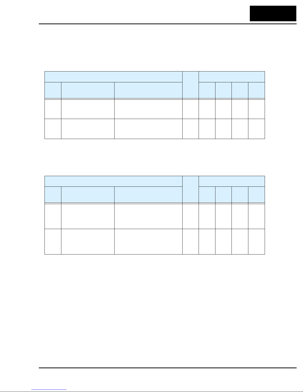
“C” Group: Intelligent Terminal Functions
Intelligent Input Terminals – The three intelligent input terminals for L100DN
DeviceNet Series inverters have 20 possible option assignments.
L100DN Inverter
27
“C” Function
Func.
Code
C_01 Terminal [1] function Select function for terminal [1]
C_02 Terminal [2] function Select function for terminal [2]
C_03 Terminal [3] function Select function for terminal [3]
Name Description
20 options (see inverter
manual)
20 options (see inverter
manual)
21 options (see inverter manual
and Note below)
NOTE: Terminal [3] can operate as the PTC (thermistor thermal protection) input. Thus,
it has the additional [PTC] terminal input (option code 19) that may be assigned.
The input logic convention is programmable for each of the three inputs. The inputs
default to normally open (active high), but you can select normally closed (active low) in
order to invert the sense of the logic.
Run
Mode
Edit
✘
✘
✘
Defaults
–FE
(CE)
[FW]00[FW]00[FW]
[STP]21[STP]21[STP]
[EXT]12[EXT]12[EXT]
00
21
12
–FU
(UL)
–F
(Jpn)
Units
—
—
—
“C” Function
Func.
Code
C_11 Terminal [1] active state Select logic convention, two
C_12 Terminal [2] active state Select logic convention, two
C_13 Terminal [3] active state Select logic convention, two
Name Description
option codes:
00... normally open [NO]
01... normally closed [NC]
option codes:
00... normally open [NO]
01... normally closed [NC]
option codes:
00... normally open [NO]
01... normally closed [NC]
Run
Mode
Edit
–FE
(CE)
✘ 00 00 00 —
✘ 00 00 00 —
✘ 00 00 00 —
Defaults
–FU
(UL)
–F
(Jpn)
Units

28
Configuring Drive Parameters
To the 15 option codes for standard L100 inverters, L100DN Series inverters remove the
code for the [AT] input, and add the following 7 options:
Input Function Summary Table
Option
Code
20 STA Start Motor ON Start motor rotation on momentary contact (uses
21 STP Stop Motor ON Stop motor rotation on momentary contact (uses
22 F/R FWD/REV ON Select reverse direction of rotation
25 DNT DeviceNet Select ON Inverter operates under DeviceNet network
27 UP Remote Control
28 DWN Remote Control
Terminal
Symbol
Function Name Description
acceleration profile)
OFF No change to motor operation
deceleration profile)
OFF No change to motor operation
OFF Select forward direction of rotation
control
OFF Inverter operates under local control (keypad and
input terminals)
ON Accelerates (increases output frequency) motor
UP Function (motorized speed pot.)
DOWN Function
(motorized speed
pot.)
OFF No change to output frequency
ON Decelerates (decreases output frequency) motor
OFF No change to output frequency
from current frequency
from current frequency
31 OPE Force Operation
from Digital
Operator
ON Forces the operator interface Run command to
over-ride commands from input terminals (such
as [FW], [RV])
OFF Run command operates normally, as configured
by A_02
NOTE: The assignment of [DNT] to an input terminal is optional. It is useful if you
need to switch between DeviceNet network control and local control during running.
Alternatively, you can use parameter P_43 DeviceNet Control Enable, which works
similarly but does not require an input terminal. If assigned, the [DNT] setting has precedence over the P_43 setting. More information is in “Step 7 – Control Test – Verify
Network Host Can Control Inverter” on page 54.
L100DN Inverter
Intelligent Output Terminals – The L100DN DeviceNet Series inverters have 5 of the
6 possible output option assignments for standard L100 inverters ([OD] is removed).
However, note that the alarm relay contact terminals [AL0], [AL1], and [AL2] are not
present on the L100DN DeviceNet Series inverters (so C_24 and C_33 are not present
on L100DN).
29
“C” Function
Func.
Code
C_21 Terminal [11] function Select function for terminal
C_22 Terminal [12] function Select function for terminal
Name Description
[11],
5 options (see inverter manual
[12],
5 options (see inverter manual)
The output logic convention is programmable for terminals [11] and [12]. The opencollector output terminals [11] and [12] default to normally open (active low), but you
can select normally closed (active high) for these terminals in order to invert the sense of
the logic.
“C” Function
Func.
Code
C_31 Terminal [11] active
state
Name Description
Select logic convention, two
option codes:
00... normally open [NO]
01... normally closed [NC]
Run
Mode
Edit
Run
Mode
Edit
–FE
(CE)
✘
✘
✘ 00 00 00 —
00
[RUN]00[RUN]00[RUN]
05
[AL]05[AL]05[AL]
–FE
(CE)
Defaults
–FU
(UL)
Defaults
–FU
(UL)
–F
(Jpn)
–F
(Jpn)
Units
—
—
Units
C_32 Terminal [12] active
state
Select logic convention, two
option codes:
00... normally open [NO]
01... normally closed [NC]
✘ 00 00 00 —
 Loading...