

Page 1
Service Manual
Data Interfaces
for HEIDENHAIN
Controls of the Series
TNC 122
TNC 124
TNC 125
TNC 131/135
TNC 145
TNC 150/151/155
TNC 246
TNC 2500
TNC 306
TNC 310
TNC 335
July 2011
TNC 351/355
TNC 360
TNC 370
TNC 406
TNC 407/415
TNC 410
TNC 425
TNC 426/430
CNC 232 B
CNC 234.xx
CNC 332
Page 2

1 How to Use this Service Manual
1.1 Target Group .......................................................................................................................................................... 5
1.2 About this Manual ................................................................................................................................................. 5
1.3 Other Documentation on Data Interfaces ........................................................................................................... 5
1.4 Meaning of the symbols used in this manual..................................................................................................... 6
2 General Information on the Data Interfaces
2.1 RS-232-C/V.24 Interface ........................................................................................................................................ 7
2.1.1 Hardware.................................................................................................................................................. 7
2.1.2 Signal levels ............................................................................................................................................. 7
2.1.3 HEIDENHAIN data transfer software....................................................................................................... 8
2.2 RS-422/V.11 Interface............................................................................................................................................ 9
2.2.1 Hardware.................................................................................................................................................. 9
2.2.2 Signal levels ........................................................................................................................................... 10
2.2.3 HEIDENHAIN data transfer software..................................................................................................... 10
2.3 Ethernet ................................................................................................................................................................ 10
2.3.1 Hardware................................................................................................................................................ 11
2.3.2 Signal structure...................................................................................................................................... 11
2.3.3 Connecting the TNC to data networks................................................................................................... 12
3 Connector Designations and Layouts
3.1 Connector Designations and Layouts of TNC 125, 131, 135, 145, 150, 151/155 ............................................ 13
3.2 Connector Designations and Layouts of TNC 122, TNC 2xx, TNC 3xx, TNC 4xx, CNC xxx .......................... 14
3.2.1 RS-232-C/V.24 data interface, 25-pin, D-sub
Flange socket with female insert........................................................................................................... 14
3.2.2 RS-232-C/V.24 data interface, 9-pin, D-sub
Flange socket with female insert........................................................................................................... 15
3.2.3 RS-422/V.11 data interface, 15-pin, D-sub
Flange socket with female insert........................................................................................................... 16
4 Wiring Diagrams of the Data Interfaces
4.1 RS-232-C/V.24 Overview.................................................................................................................................... 19
4.2 RS-422/V.11 Overview ........................................................................................................................................ 20
4.3 Ethernet Overview............................................................................................................................................... 20
4.4 RS-232-C/V.24 Diagrams..................................................................................................................................... 20
4.5 RS-422/V.11 Diagram .......................................................................................................................................... 33
4.6 V.11 -> V.24 Converter......................................................................................................................................... 33
5 Operating Modes of the Data Interfaces
5.1 Operating Modes on TNC 125, 131, 135, 145, 150, 151/155............................................................................. 35
5.2 Operating Modes on TNC 122 to TNC 430 ........................................................................................................ 36
6 Machine Parameters for the Data Interfaces
6.1 Machine Parameters for TNC 125, 131, 135, 145, 150, 151/155, 351/355 ....................................................... 39
6.1.1 Overview................................................................................................................................................ 39
6.1.2 Description of the machine parameters................................................................................................. 40
6.2 Machine Parameters for for TNC 122/124 ......................................................................................................... 48
6.2.1 Overview................................................................................................................................................ 48
6.2.2 Description of the machine parameters................................................................................................. 48
Juni 2011
Page 3

6.3 Machine Parameters for TNC 232/246............................................................................................................... 49
6.3.1 Overview................................................................................................................................................ 49
6.3.2 Description of the machine parameters................................................................................................. 50
6.4 Machine Parameters for TNC 306/335/360/2500/CNC 234/TNC 370 ............................................................. 51
6.4.1 Overview................................................................................................................................................ 51
6.4.2 Description of the machine parameters................................................................................................. 52
6.5 Machine Parameters for TNC 310/410............................................................................................................... 54
6.5.1 Overview................................................................................................................................................ 54
6.5.2 Description of the machine parameters................................................................................................. 55
6.6 Machine Parameters for TNC 406/407/415/425................................................................................................ 56
6.6.1 Overview................................................................................................................................................ 56
6.6.2 Description of the machine parameters of TNC 406/407/415 .............................................................. 57
6.6.3 Description of the machine parameters of TNC 415 B/425 ................................................................... 60
6.7 Machine Parameters for TNC 426/430............................................................................................................... 63
6.7.1 Overview................................................................................................................................................ 63
6.7.2 Description of the machine parameters................................................................................................. 64
7 Ethernet Card (Option) in TNC 426/430 Controls
7.1 Installing the Ethernet Card................................................................................................................................ 65
7.2 Connecting the Ethernet Hardware ................................................................................................................... 66
7.3 Ethernet Configuration in the TNC .................................................................................................................... 68
7.3.1 Settings in DEFINE NET......................................................................................................................... 68
7.3.2 Settings in DEFINE MOUNT.................................................................................................................. 72
7.4 Checking the Connection to the Server............................................................................................................. 79
7.5 Finding the Hardware Address of the Ethernet Card ....................................................................................... 80
7.6 Working with the Ethernet Interface ................................................................................................................. 81
7.6.1 Establish network connection (mount) .................................................................................................. 81
7.6.2 Unmounting a network connection........................................................................................................ 83
8 Error Messages and their Causes
8.1 Error Messages Related to the RS-232C and RS-422 Interfaces...................................................................... 85
8.1.1 Error messages at the TNC in the ME mode......................................................................................... 85
8.1.2 Error messages at the ME..................................................................................................................... 86
8.1.3 Error messages at the FE in the ME mode............................................................................................ 87
8.1.4 Error messages at the TNC in the FE mode .......................................................................................... 89
8.1.5 Error messages during data transfer...................................................................................................... 90
8.2 Ethernet Error Messages..................................................................................................................................... 91
9Tables
9.1 7-Bit ASCII Code................................................................................................................................................... 93
9.2 Powers of 2........................................................................................................................................................... 97
HEIDENHAIN Service-Handbuch Datenschnittstellen
Page 4

1 How to Use this Service Manual
1.1 Target Group
This Service Manual has been written for specialist electricians for service, maintenance and
commissioning as well as for end users of machine tools with HEIDENHAIN controls.
1.2 About this Manual
This manual provides support for connecting, machine parameter setting and troubleshooting
the data interfaces RS-232-C, RS-422 and Ethernet of the following HEIDENHAIN controls.
TNC 122
TNC 124
TNC 125
TNC 131/135
TNC 145
TNC 150/151/155
TNC 246
TNC 2500
TNC 306
TNC 310
TNC 335
TNC 351/355
TNC 360
TNC 370
TNC 406
TNC 407/415
TNC 410
TNC 425
TNC 426/430
CNC 232B
CNC 234.xx
CNC 332
1.3 Other Documentation on Data Interfaces
For information on the data interfaces of the HEIDENHAIN controls as of iTNC 530, TNC 320,
TNC 620, etc., please refer to the respective Technical Manual, User's Manual and Service
Manual.
June 2011 1 – 5
Page 5

1.4 Meaning of the symbols used in this manual
DANGER
Attention
Note
Failure to comply with this information could result in most serious or fatal injuries, and/or
in substantial material damage.
Failure to comply with this information could result in injuries and interruptions of operation,
including material damage.
These boxes contain important and useful information.
1 – 6 HEIDENHAIN Service Manual for Data Interfaces
Page 6
2 General Information on the Data Interfaces
2.1 RS-232-C/V.24 Interface
RS-232-C is the designation of a serial interface for transfer rates of up to 19,200 bps based on
the American EIA standard of the same name. Data transfer is executed asynchronously, with a
start bit before each character and one or two stop bits after each character.
The interface is designed for transmission distances of up to 30 meters.
The RS-232-C interface has been adopted with slight modifications and introduced into Europe
as the V.24 interface. The relevant German standard is DIN 66020.
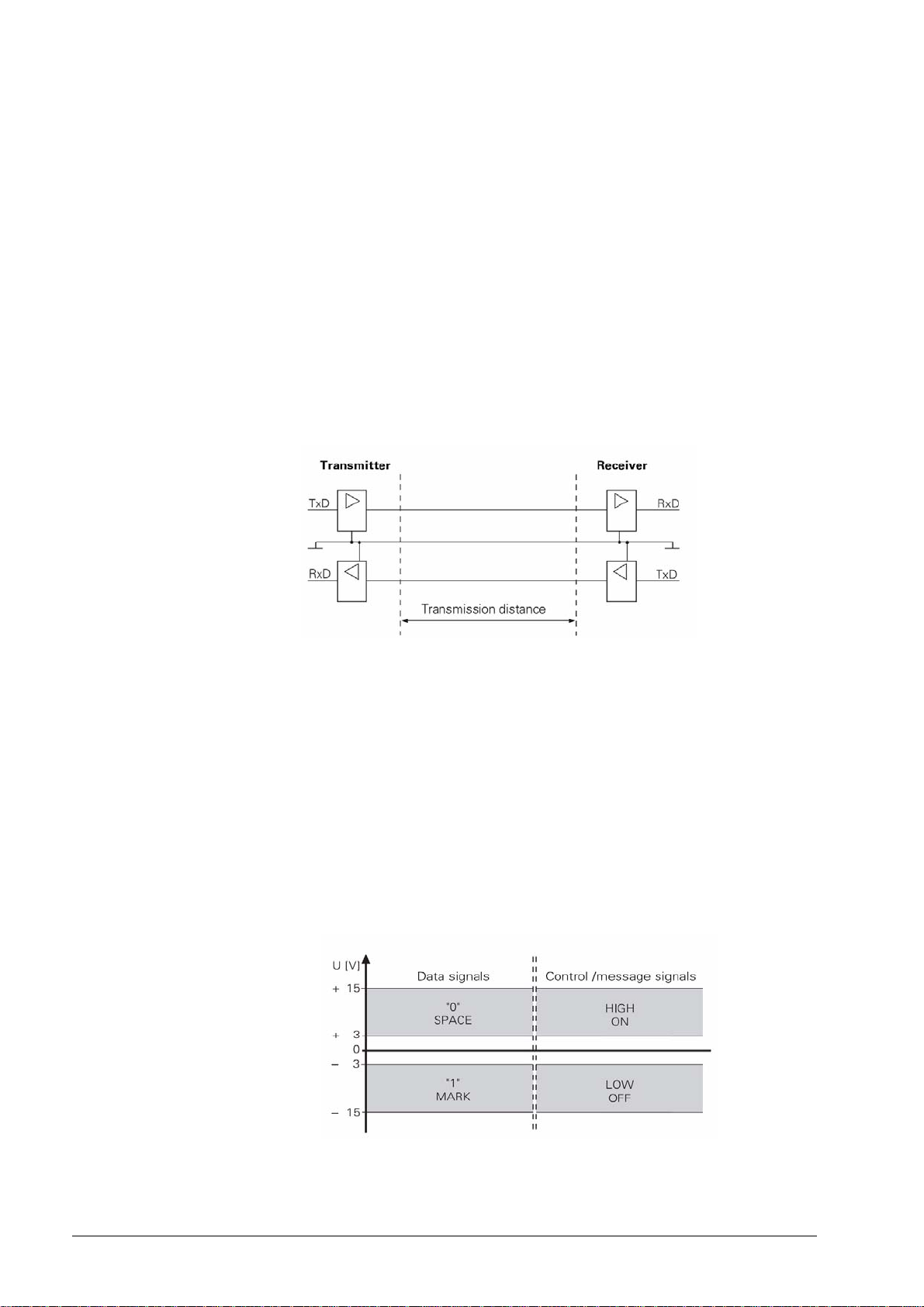
2.1.1 Hardware
The physical connection between two RS-232-C/V.24 interfaces is an asymmetrical line, i.e. the
common ground connection between transmitter and receiver is used as a return wire.
Physical connections:
2.1.2 Signal levels
With the RS-232-C/V.24 interface one must differentiate between two different signal lines and
their levels.
Data lines:
The data signals are defined as being logical one (MARK) over the range –3 V to +15 V and
logical zero (SPACE) over the range +3 V to +15 V.
Control and signal lines:
These signals are defined as being ON (High) over the range +3 V to +15 V and as OFF (Low)
over the range –3 V to –15 V.
For all of the signals, the voltage range from –3 V to +3 V is not defined as a logic level and can
therefore not be evaluated.
June 2011 2 – 7
Page 7
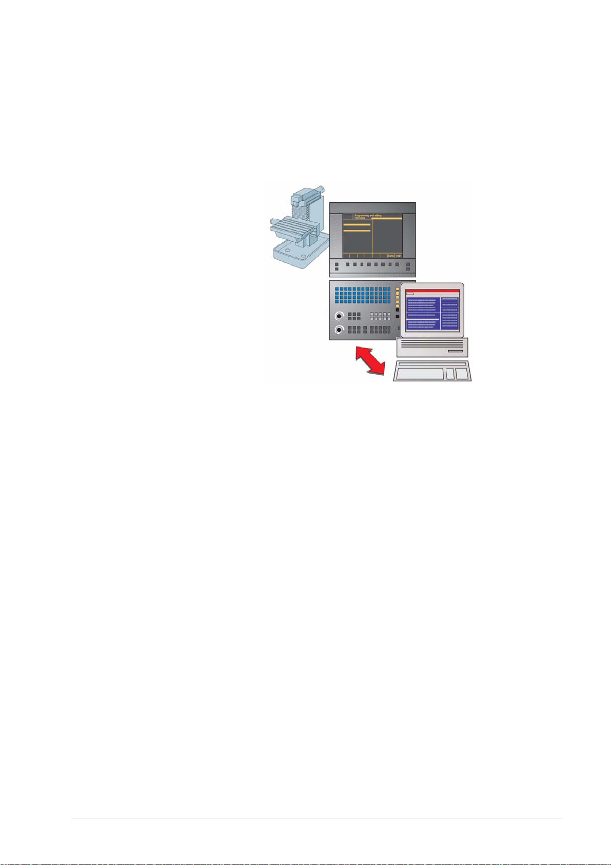
2.1.3 HEIDENHAIN data transfer software
TNCremoNT is a software package for communication between PCs and HEIDENHAIN controls
or programming stations.
Data transfer is carried out over the Ethernet network or the serial interface.
TNCremoNT can be run on all common personal computers.
A version of Windows 2000, XP, Vista or 7 must be used as operating system.
Windows 2000, Windows XP, Windows Vista and Windows 7 are registered trademarks of
the Microsoft Corporation.
Functions of
TNCremoNT
The TNCremoNT software package includes:
TNCremoNT
Convenient data transfer and management functions that are operated from the PC
Screendump of the control’s screen
Read-out of the control’s log
Pallet management for creating, editing and transmitting pallet tables
Creating a service file
TNCserver
Transfer via the serial interface with operation on the control for all HEIDENHAIN controls
and many HEIDENHAIN position displays.
Support of all HEIDENHAIN protocols including simple data input/output.
TNCbackup
Features for data backup and restoration
TNCcmd
Command line tool for all transfer functions
TNClog
Log viewer to view and filter the control's log file
TNCremoPlus (available for a fee)
View control screen (live screen)
The selection of features you can use in TNCremoNT depends on your control. Refer to the
overview of features for more detailed information.
2 – 8 HEIDENHAIN Service Manual for Data Interfaces
Page 8
2.2 RS-422/V.11 Interface
As the features of the V.24/RS-232-C interface are limited, the V.11/RS-422 interface was
developed. This interface is also standardized, but operates symmetrically.
The RS-422/V.11 serial interface is suitable for data transfer rates up to 10 Mbps.
At a baud rate of 38,400 bauds, data can be transferred over 1 km cable.
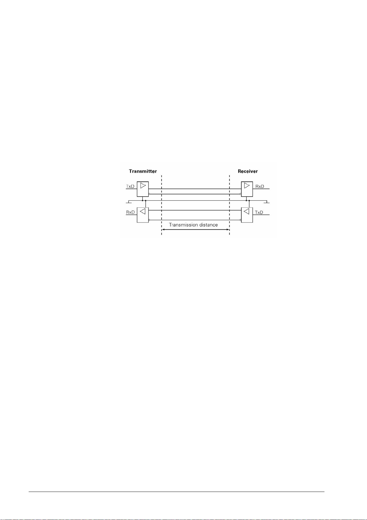
2.2.1 Hardware
The V.11/RS-422 standard operates with differential voltages. This offers the advantage that
interferences act on both signal lines equally and simultaneously over the transmission distance.
As the receiver only evaluates the differential voltages of the two signal lines, interferences are
not relevant. By this means, considerably longer lines can be installed, and the transfer rate is
much higher, as interferences are limited.
Physical connections:
June 2011 2 – 9
Page 9
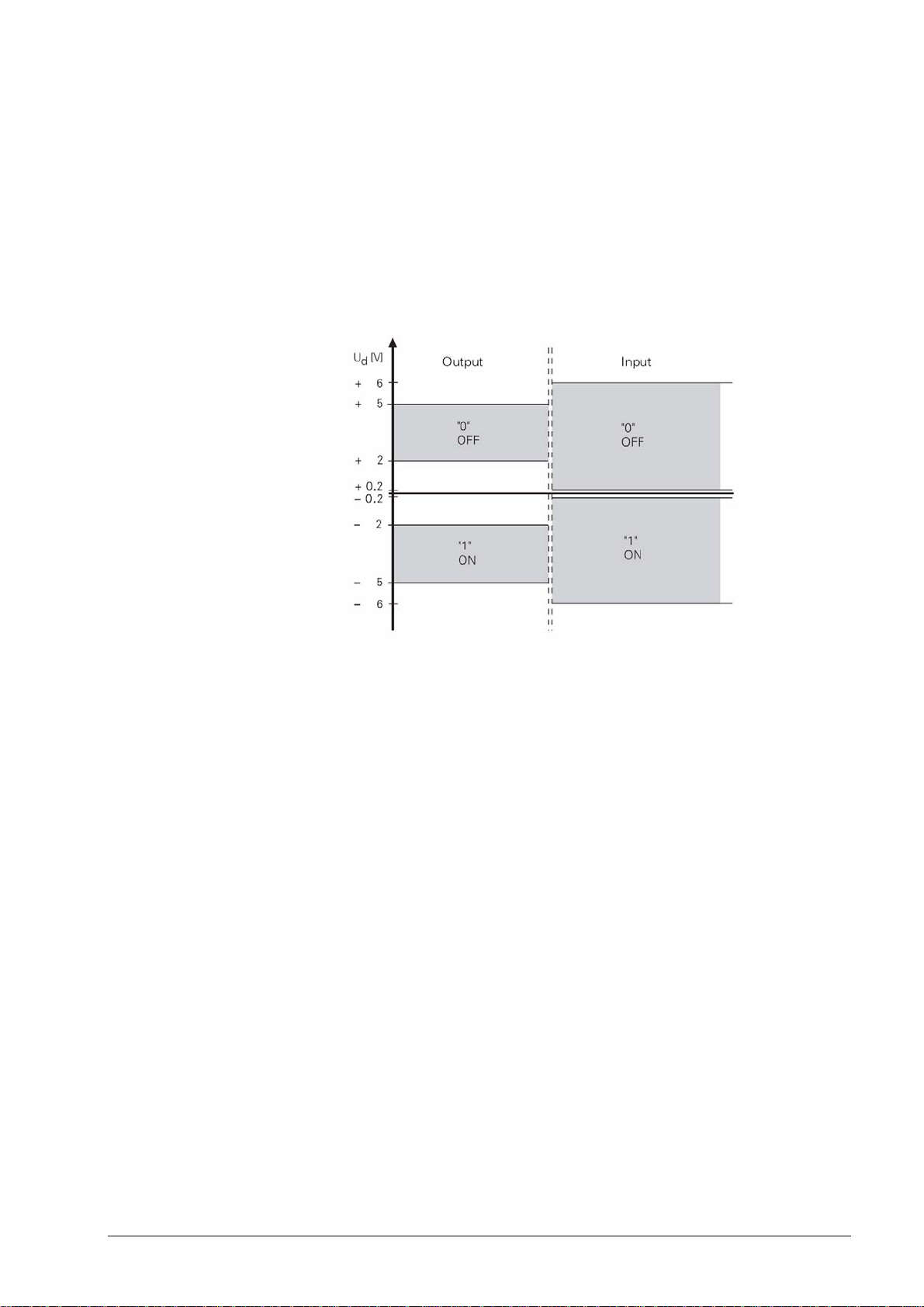
2.2.2 Signal levels
With the V.11/RS-422 interface the signals are both transmitted and received as differential
voltage.
A positive differential voltage means a logical zero (OFF), a negative differential voltage means
a logical one (ON).
Differential voltages between
U
= 2 V and U
dmin
= 5 V are output; the control detects the differential voltages
dmax
between
U
= 0.2 V and U
dmin
= 6 V as logically defined levels.
dmax
2.2.3 HEIDENHAIN data transfer software
See chapter 2.1.3
2.3 Ethernet
Ethernet technology is most frequently used in local networks. It was developed by Digital
Equipment, Intel and Xerox in 1982. Ethernet operates at a data transfer rate of up to 100 Mbps
(Fast Ethernet); the hardware versions most frequently used - such as 10Base2 (Thin Ethernet,
Cheapernet), 10Base5 (Thick Ethernet, Yellow Cable) or 10BaseT (Twisted Pair) - operate at
10 Mbps. They differ in price, routing complexity or network topology, but not in the method of
accessing media.
The data transfer rate strongly depends on the amount of traffic at the time on the net.
Realistic values: NC program up to 200 Kbps
ASCII file up to 1 Mbps
2 – 10 HEIDENHAIN Service Manual for Data Interfaces
Page 10

2.3.1 Hardware
2.3.2 Signal structure
The integrated Ethernet expansion card provides you with both the 10Base2 (BNC) port and the
10BaseT (twisted pair). You can only use one of the two connections at one time. Both
connections are electrically isolated from the control electronics.
Connection and wiring diagrams see chapter 7.2, pin layouts see chapter 3.2.
X26 Ethernet interface, BNC connection (coaxial cable, 10Base2)
The 10Base2 connection is also commonly known as ThinEthernet or CheaperNet.
You connect the TNC with your network via BNC-T connector. The maximum cable length is
185 m (coaxial cable). The network topology is a linear bus. The "open" ends of the bus must be
terminated with terminating resistors.
X25 Ethernet interface, RJ45 connection (10BaseT)
The twisted-pair cable of the 10BaseT connector may be either shielded or non-shielded.
Maximum cable length: non-shielded: 100 m
shielded: 400 m
The network topology is a star connection. This means a central node establishes the connection
to the other participants.
Ethernet frames are transferred in Manchester code which is a self-clocking code. The
synchronization or the transfer of a transmit clock pulse is executed such that each bit is
transmitted inverted in the first half of the transfer period, i.e. the bit rate is half the baud rate.
A data rate of 10 Mbps results in a bit time of 100 ns. Carrier detect (activity on the cable) is
indicated by the presence of signal level changes. If the signal level does not change in a bit time
interval between 0.75 and 1.25 after the last transition, no carrier is detected (see figure).
The network settings of the TNC are described in the Technical Manual and in chapter 7
(Ethernet) of this Service Manual.
June 2011 2 – 11
Page 11
2.3.3 Connecting the TNC to data networks
Note
The HEIDENHAIN control models TNC 426/TNC 430 can optionally1) be equipped with an
Ethernet data interface. Via this interface, TNC 426/TNC 430 can be integrated into data
networks as client.
The TNC transfers data using the TCP/IP protocol (Transmission Control Protocol / Internet
Protocol) and with the aid of the NFS, version 2 (Network File System). Since TCP/IP and NFS
have been implemented in UNIX systems in the first place, you can usually connect the TNC in
the UNIX world without any additional software.
The PC world with Microsoft operating systems, however, also works with TCP/IP, but not with
NFS. For this reason, additional software is usually required for PC networks. HEIDENHAIN
recommends the following network software:
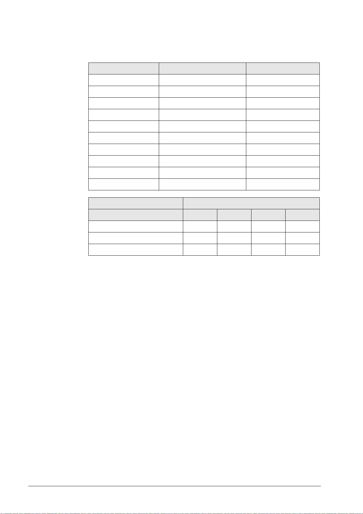
Operating system Network Software
WIN 2000
WIN XP
CIMCO NFS
available from HEIDENHAIN under ID 339737-xx
WIN Vista
WIN 7
In principle, other NFS servers can be used as well.
However, due to the great variety of software providers, HEIDENHAIN is not a in position to
provide technical support in adapting other NFS servers.
1)
Control models that can be operated with the Ethernet card: see chapter 2.
The network settings of the TNC are described in the Technical Manual and in
chapter 7 (Ethernet) of this Service Manual.
2 – 12 HEIDENHAIN Service Manual for Data Interfaces
Page 12
3 Connector Designations and Layouts
3.1 Connector Designations and Layouts of TNC 125, 131, 135, 145, 150, 151/155
RS-232-C/V.24 data interface, 14-pin, Amphenol
Flange socket with female insert
Pin no. Assignment Designation
1 GND Chassis ground
2 Not assigned
3 Not assigned
4 Not assigned
5 RTS Request to Send
6 DSR Data Set Ready
7 Not assigned
8 Not assigned
9 Not assigned
10 Not assigned
11 DTR Data Terminal Ready
12 TxD Transmit Data
13 CTS Clear to Send
14 RXD Receive Data
Chassis Ext. shield
June 2011 3 – 13
Page 13
3.2 Connector Designations and Layouts of TNC 122, TNC 2xx, TNC 3xx, TNC 4xx, CNC xxx
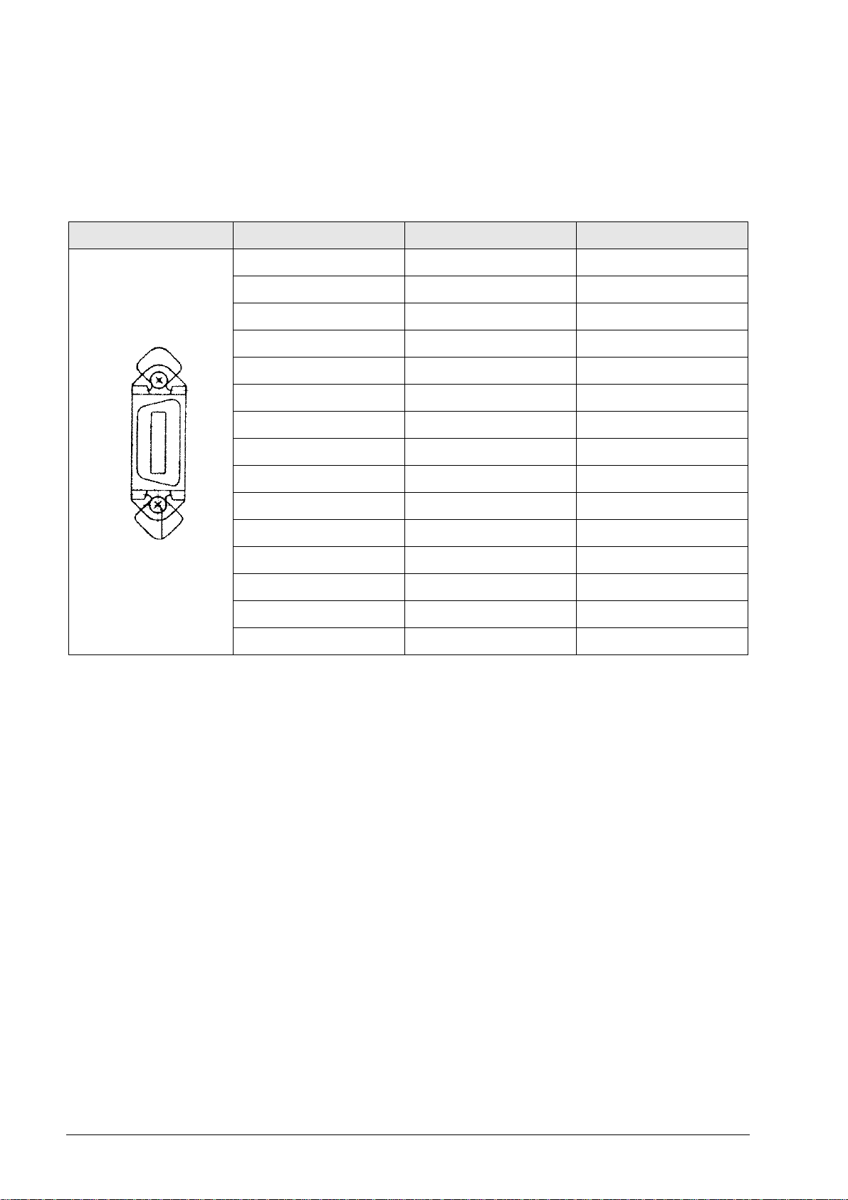
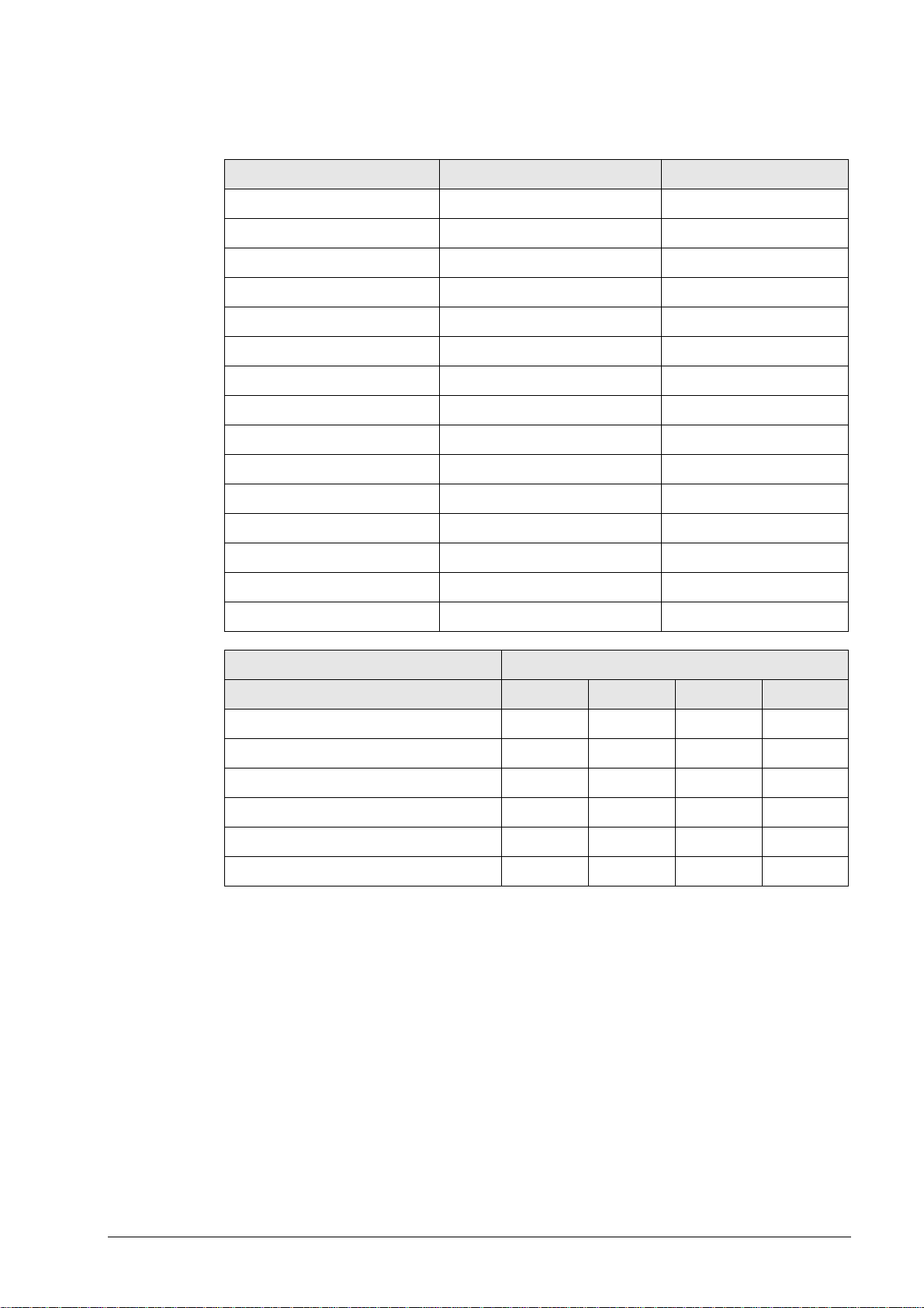
3.2.1 RS-232-C/V.24 data interface, 25-pin, D-sub
Flange socket with female insert
Pin no. Assignment Designation
1 Shield Chassis Ground
2 RxD Receive Data
3 TxD Transmit Data
4 CTS Clear to Send
5 RTS Request to Send
6 DTR Data Terminal Ready
7 GND (0 V *2) Signal Ground
8 to 19 Not assigned
20 DSR Data Set Ready
21 to 25 Not assigned
Chassis External shield = Chassis
Control model RS-232-C/V.24 connector
X21 X25 X6 X26
TNC 122 x
TNC 246 x
TNC 2500/B/C x
TNC 306 x
TNC 335 x
TNC 351/355 x
TNC 360 x
TNC 406 x
TNC 407 x
TNC 410 x
TNC 415/B x
TNC 425 x
TNC 426 x
TNC 430 x
CNC 232B x
CNC 234.xxx x
CNC 332 x
3 – 14 HEIDENHAIN Service Manual for Data Interfaces
Page 14
3.2.2 RS-232-C/V.24 data interface, 9-pin, D-sub
Flange socket with female insert
Pin no. Assignment Designation
1 Shield Chassis Ground
2 TxD Transmit Data
3 RxD Receive Data
4 DSR Data Set Ready
5 GND Signal Ground
6 DTR Data Terminal Ready
7 CTS Clear to Send
8 RTS Request to Send
9 Not assigned
Chassis External shield = Chassis
Control model RS-232-C/V.24 connector
X21
TNC 124 x
TNC 310 x
TNC 370 x
June 2011 3 – 15
Page 15
3.2.3 RS-422/V.11 data interface, 15-pin, D-sub
Flange socket with female insert
Pin no. Assignment Designation
1 Shield Chassis Ground
2 RxD Receive Data
3 CTS Clear to Send
4 TxD Transmit Data
5 RTS Request to Send
6 DSR Data Set Ready
7 DTR Data Terminal Ready
8 GND Signal Ground
9 RxD Receive Data
10 CTS Clear to Send
11 TxD Transmit Data
12 RTS Request to Send
13 DSR Data Set Ready
14 DTR Data Terminal Ready
15 Do not assign
Control model RS-422/V.11 connector
X22
TNC 406 x
TNC 407 x
TNC 415/B x
TNC 425 x
TNC 426 x
TNC 430 x
3 – 16 HEIDENHAIN Service Manual for Data Interfaces
Page 16

X25 Ethernet interface, RJ45 connection, 10BaseT
Maximum cable length: non-shielded: 100 m
shielded: 400 m
RJ45 connection (female) 8-pin Assignment
1TX+
2TX–
3REC+
4 Not assigned
5 Not assigned
6REC–
7 Not assigned
8 Not assigned
X26 Ethernet interface, BNC connection, 10Base2 (coaxial cable)
Maximum cable length: 180 m
BNC connection (female) Assignment
Inner conductor (core) Data (RXI, TXD)
Shield GND
Control model Ethernet connector
(option)
X25 X26
TNC 426.B x x
TNC 430.A x x
TNC 426M/430M x x
June 2011 3 – 17
Page 17

3 – 18 HEIDENHAIN Service Manual for Data Interfaces
Page 18
4 Wiring Diagrams of the Data Interfaces
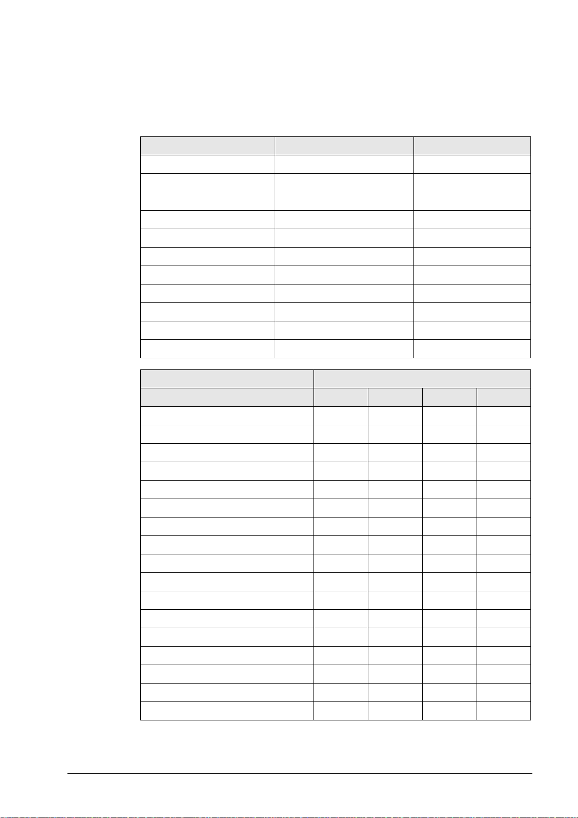
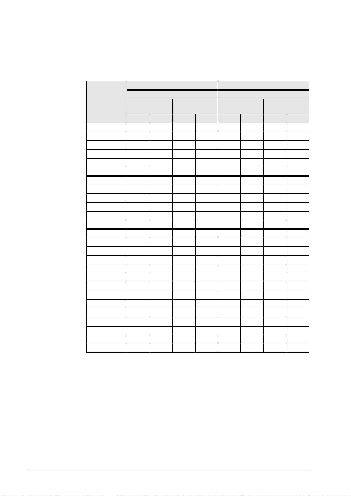
4.1 RS-232-C/V.24 Overview
Connection of peripheral, 25-pin Connection of peripheral, 9-pin
Wiring diagram for connection Wiring diagram for connection
direct
Control HW SW HW SW HW SW HW SW
TNC 122 11122 1 10103 4
TNC 124 - - 1414- - 1515
TNC 125 13 13 7 8 9 9 5 6
TNC 131 13 13 7 8 9 9 5 6
TNC 135 13 13 7 8 9 9 5 6
TNC 145 13 13 7 8 9 9 5 6
TNC 150 13 13 7 8 9 9 5 6
TNC 151/155 13 13 7 8 9 9 5 6
TNC 246 11122 1 10103 4
TNC 2500/B/C11122 1 10103 4
TNC 306 11122 1 10103 4
TNC 310 - - 1414- - 1515
TNC 335 11122 1 10103 4
TNC 351/355 11 12 2 1 10 10 3 4
TNC 360 11122 1 10103 4
TNC 370 - - 141410101515
TNC 406 11122 1 10103 4
TNC 407 11122 1 10103 4
TNC 410 11122 1 10103 4
TNC 415/B11122 1 10103 4
TNC 425 11122 1 10103 4
TNC 426 11122 1 10103 4
TNC 430 11122 1 10103 4
CNC 232B 11 12 2 1 10 10 3 4
CNC 234.XXX 11 12 2 1 10 10 3 4
CNC 332 11122 1 10103 4
via adapter and
JH cable
direct
via adapter and
JH cable
HW: Wiring diagram for data transfer with hardware handshake
SW: Wiring diagram for data transfer with software handshake
June 2011 4 – 19
Page 19
4.2 RS-422/V.11 Overview
Note
Control model Connection diagram
TNC 406 16
TNC 407 16
TNC 415/B 16
TNC 425 16
TNC 426 16
TNC 430 16
V.11 -> V.24 converter 17
4.3 Ethernet Overview
Control model Connection diagram
TNC 426 Chapter 7.2
TNC 430 Chapter 7.2
4.4 RS-232-C/V.24 Diagrams
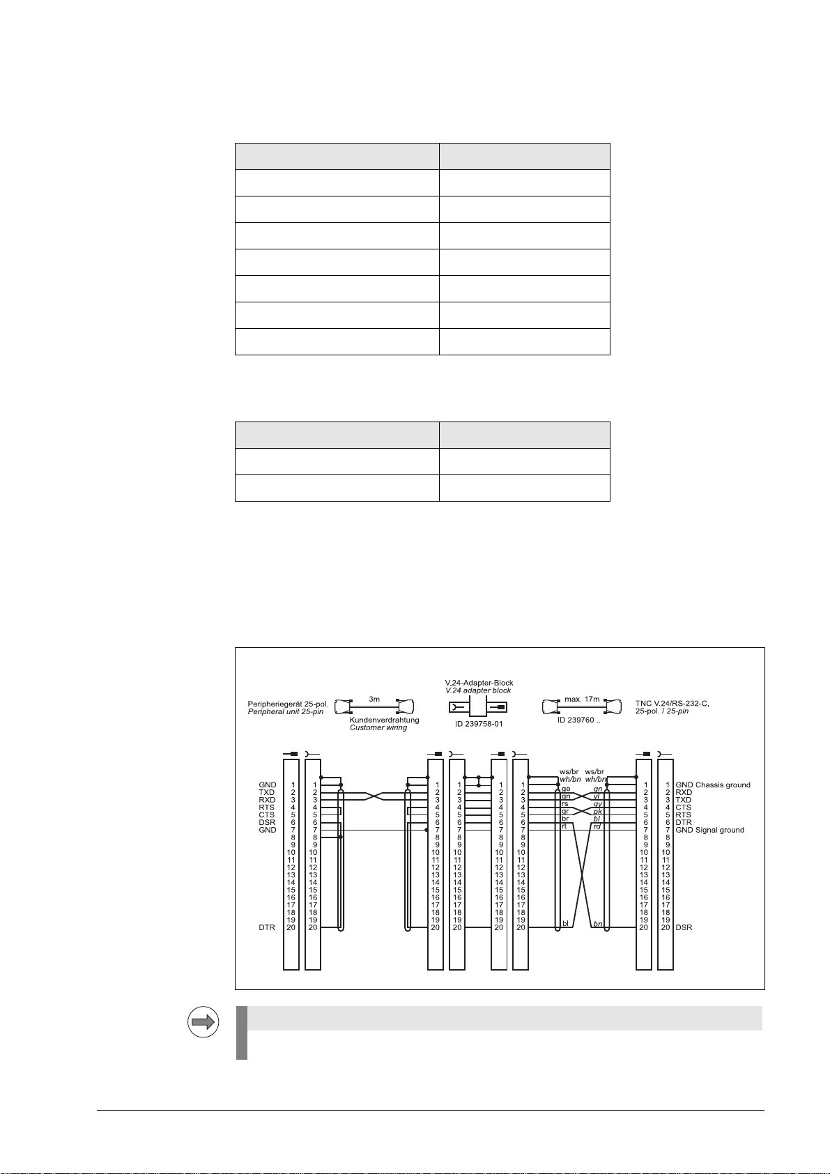
Diagram no. 1
RS-232-C/V.24 with adapter block for software handshake,
TNC 25-pin / peripheral 25-pin
This wiring only allows transfer stop with DC3 (software handshake).
4 – 20 HEIDENHAIN Service Manual for Data Interfaces
Page 20
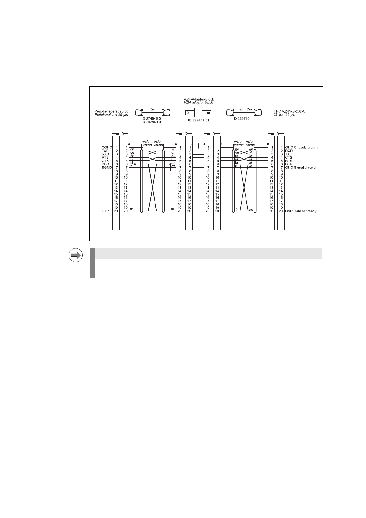
The RS-232-C-/V.24 data interface has different pin layouts at the logic unit and the V.24 adapter
Note
block.
Diagram no. 2
RS-232-C/V.24 with adapter block for hardware handshake,
TNC 25-pin / peripheral 25-pin
If the pin layout of your peripheral unit differs from the above layout, the HEIDENHAIN
connecting cable cannot be used.
June 2011 4 – 21
Page 21

Diagram no. 3
RS-232-C/V.24 with adapter block for hardware handshake,
TNC 25-pin / peripheral 9-pin
1)
Customer wiring or part available on market
4 – 22 HEIDENHAIN Service Manual for Data Interfaces
Page 22
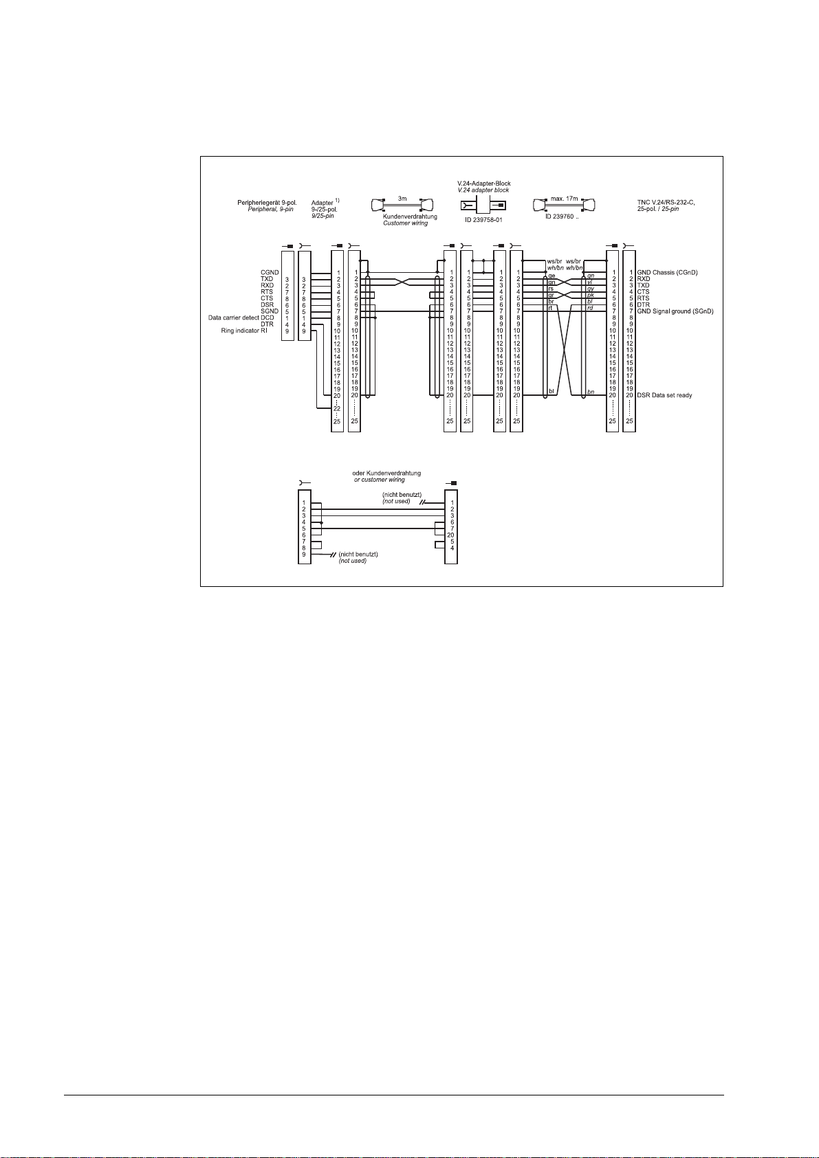
Diagram no. 4
RS-232-C/V.24 with adapter block for software handshake,
TNC 25-pin / peripheral 9-pin
1)
Customer wiring or part available on market
June 2011 4 – 23
Page 23
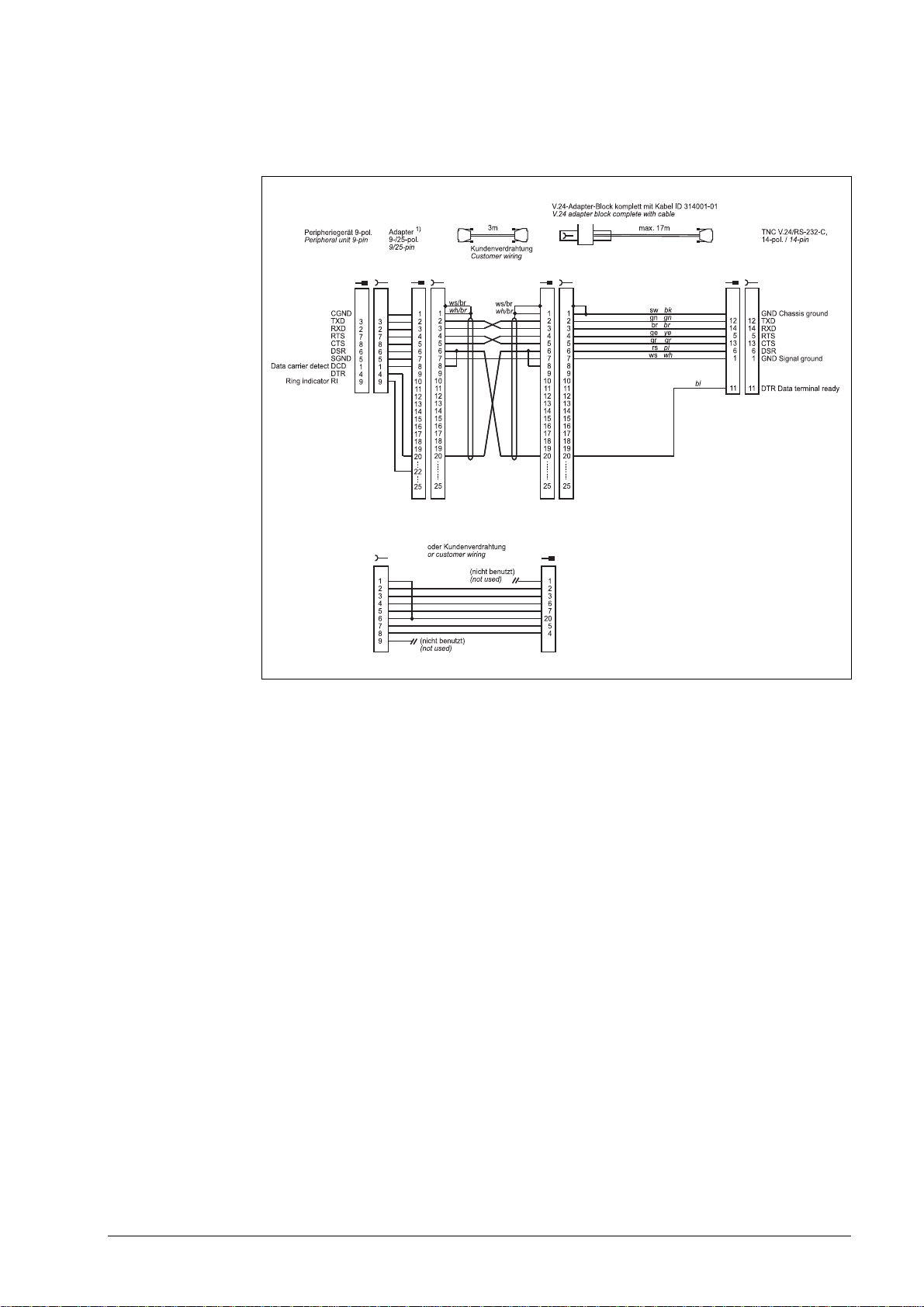
Diagram no. 5
RS-232-C/V.24 with adapter block for software handshake,
TNC 25-pin / peripheral 9-pin
1)
Customer wiring or part available on market
4 – 24 HEIDENHAIN Service Manual for Data Interfaces
Page 24
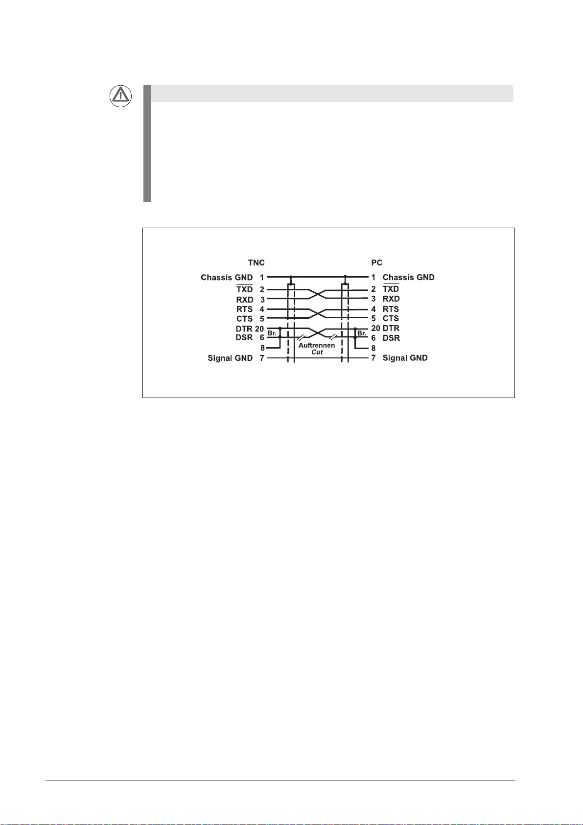
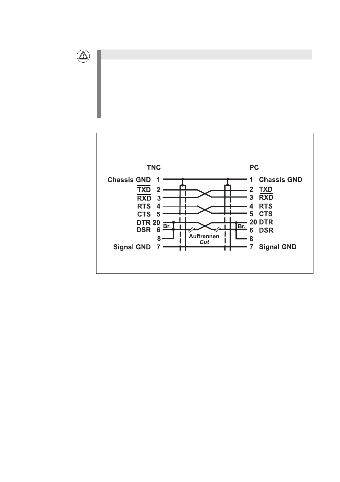
Attention
This modification applies for hardware handshake with TNC 145 to TNC 155. In these
control models, the RTS pin is not connected but tied high internally.
The following modification is required for hardware handshake:
Cut the line on both sides between DRS and DTR and short-circuit DSR with DTR
(at the PC: pin 6 with pin 20).
Without this modification, data transfer using hardware handshake is not only stopped but
aborted immediately (like "power off).
Do not use this configuration for TNC 335 with new hardware.
June 2011 4 – 25
Page 25
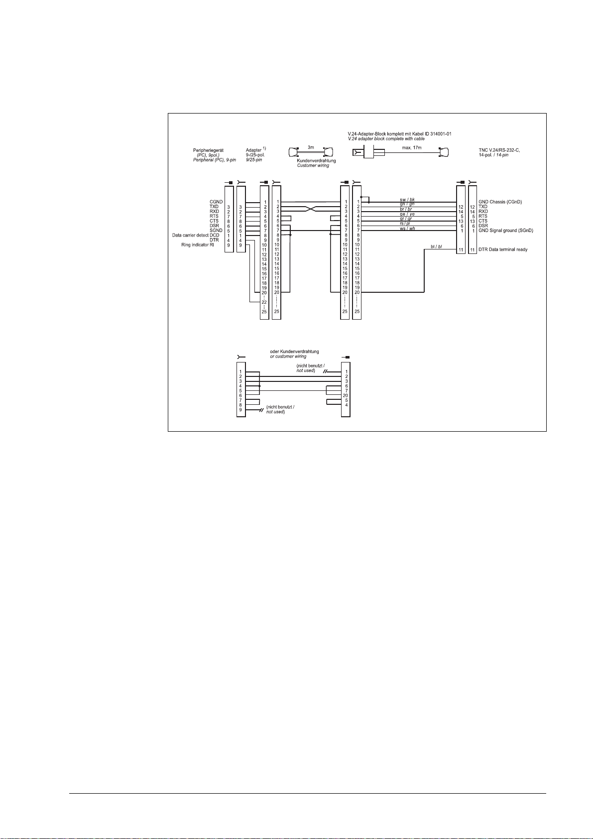
Diagram no. 6
RS-232-C/V.24 with adapter block for software handshake,
TNC 14-pin / peripheral 9-pin
1)
Customer wiring or part available on market
4 – 26 HEIDENHAIN Service Manual for Data Interfaces
Page 26
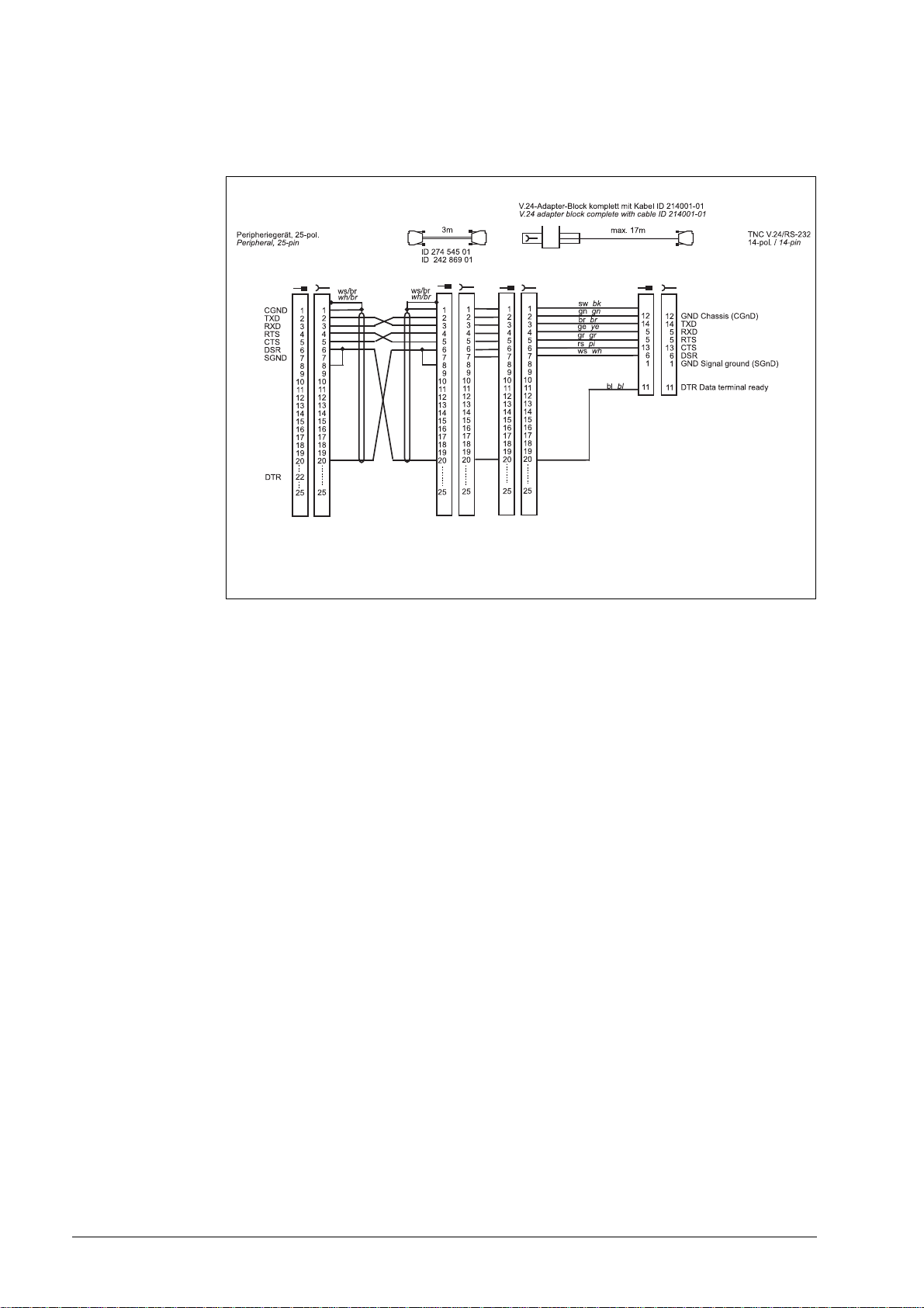
Diagram no. 7
RS-232-C/V.24 with adapter block for hardware handshake,
TNC 14-pin / peripheral 25-pin
June 2011 4 – 27
Page 27
Attention
This modification applies for hardware handshake with TNC 145 to TNC 155. In these
control models, the RTS pin is not connected but tied high internally.
The following modification is required for hardware handshake:
Cut the line on both sides between DRS and DTR and short-circuit DSR with DTR
(at the PC: pin 6 with pin 20).
Without this modification, data transfer using hardware handshake is not only stopped but
aborted immediately (like "power off).
Do not use this configuration for TNC 335 with new hardware.
4 – 28 HEIDENHAIN Service Manual for Data Interfaces
Page 28
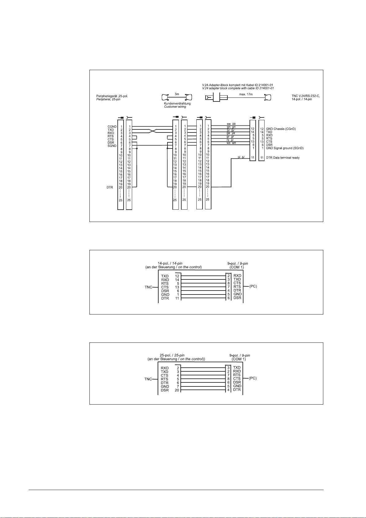
Diagram no. 8
RS-232-C/V.24 with adapter block for software handshake,
TNC 14-pin / peripheral 25-pin
Diagram no. 9
RS-232-C /V.24 direct connection, TNC 14-pin / peripheral 9-pin
Diagram no. 10
RS-232-C /V.24 direct connection, TNC 25-pin / peripheral 9-pin
June 2011 4 – 29
Page 29
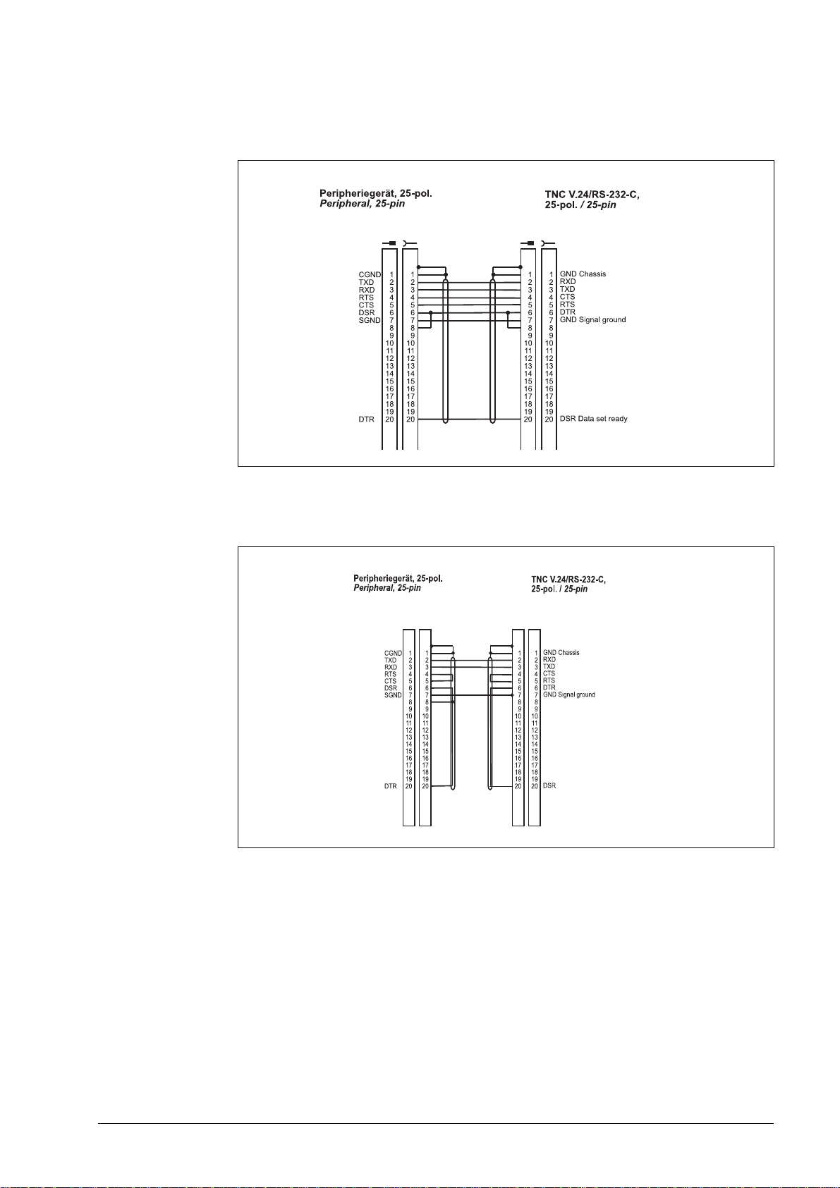
Diagram no. 11
RS-232-C/V.24 direct connection for hardware handshake,
TNC 25-pin / peripheral 25-pin (1:1)
Diagram no. 12
RS-232-C/V.24 direct connection for software handshake,
TNC 25-pin / peripheral 25-pin (1:1)
4 – 30 HEIDENHAIN Service Manual for Data Interfaces
Page 30
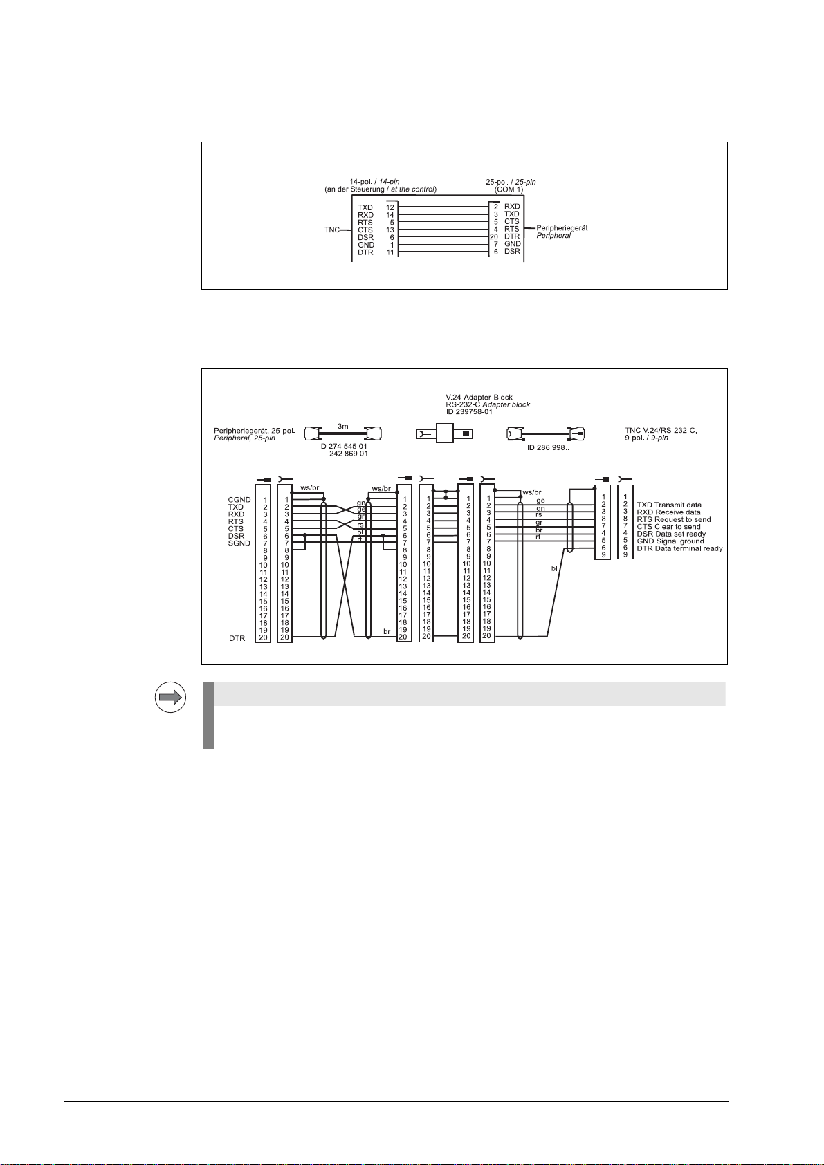
Diagram no. 13
Note
RS-232-C /V.24 direct connection, TNC 14-pin / peripheral 25-pin
Diagram no. 14
RS-232-C/V.24 with adapter block for hardware handshake,
TNC 9-pin / peripheral 25-pin
If the pin layout of your peripheral unit differs from the above layout, the HEIDENHAIN
connecting cable may not be used.
June 2011 4 – 31
Page 31

Diagram no. 15
RS-232-C/V.24 with adapter block for hardware handshake,
TNC 9-pin / peripheral 9-pin
1)
Customer wiring or part available on market
4 – 32 HEIDENHAIN Service Manual for Data Interfaces
Page 32

4.5 RS-422/V.11 Diagram
Note
Note
Diagram no. 16
RS-422/V.11 data interface
The RS-422-/V.11 data interface has the same pin layout at the logic unit X22 and at the V.11
adapter block.
4.6 V.11 -> V.24 Converter
Diagram no. 17
The adapter can be ordered, e.g., from WIESEMANN & THEIS GmbH (www.wut.de).
June 2011 4 – 33
Page 33

4 – 34 HEIDENHAIN Service Manual for Data Interfaces
Page 34

5 Operating Modes of the Data Interfaces
5.1 Operating Modes on TNC 125, 131, 135, 145, 150, 151/155
One or several operating modes are available, depending on the control model.
Control model Operating mode
ME FE EXT
TNC 125 x
TNC 131 x
TNC 135 x
TNC 145 x
TNC 150 x
TNC 151/155 B/Q
TNC 151/155 A/P
ME:
For connection of the HEIDENHAIN magnetic tape unit MP 101/102 or other peripheral units.
Data format (7 data bits, 1 stop bit, even parity) and baud rate (2400) are adapted to the FE.
FE:
For connection of the HEIDENHAIN floppy-disk unit FE 401 or other peripheral units. Data
transfer is executed with a special protocol (blockwise transfer) to back up data. Data format
(7 data bits, 1 stop bit, even parity), baud rate (9600) and transfer protocol are adapted to the FE.
EXT:
For adaptation of data transfer in standard data format and for blockwise transfer to peripheral
units. The interface for data transfer is adapted via machine parameters; any baud rate can be
selected.
1)
Selection via MOD
2)
Selection via machine parameter
1)
2)
xxx
xxx
April 2010 5 – 35
Page 35

5.2 Operating Modes on TNC 122 to TNC 430
One or several operating modes are available, depending on the model.
Control model Operating mode
ME FE EXT LSV2 Screen
dump
Host
operation
TNC 122 x x x
TNC 124 x x x
TNC 131 x
TNC 135 x
TNC 145 x
TNC 150 x
TNC 151
TNC 155
CNC 232
CNC 232B
CNC 234
CNC 234.xxx
1)
1)
1)
1)
1)
1)
x
xx 5)x
5)
xxx
xxx
xxx
xxx
CNC 332 x x x
TNC 246 x x x x
TNC 2500/B/C x
1)
xx x
DNC Log
TNC 306 x x x
TNC 310 x x x x x x
TNC 320 x x x x
TNC 335 x x x x
TNC 351/355 x x x x
TNC 360 x
CONTOUR 12
1)
1)
xx x
xx
TNC 370 x x x x
TNC 406
TNC 407 x x x x
2)
xxxxxx x
3)
3)
x
3)
x
x
TNC 410 x x x x x x
TNC 415 x x x
TNC 415B x x x x
TNC 425 x x x x
TNC 426 B / 430 x x x x
3)
4) 6)
xx
6)
x
3)
x
6)
x
iTNC 530 7) xxxx xx
TNC 6xx
7)
xxxx xx
5 – 36 HEIDENHAIN Service Manual for Data Interfaces
Page 36

Control model Operating mode
MANUALplus M
7)
MANUALplus 3110
CNC PILOT 3190
CNC PILOT 6xx
GrindPlusIT
MillPlus
7)
xx
MillPlusIT V600
7)
7)
xxx xx
7)
xx
7)
xxxx xx
ME FE EXT LSV2 Screen
dump
Host
operation
DNC Log
x
7)
x
x
1)
The transfer rate must be set to 9600 baud.
2)
Change of directory is not possible.
3)
Machine must support LSV2/DNC operation.
4)
File server (LSV2) as of software versions 280 462 05, 280 470 01, 280 472 01 only
5)
TNC 155B
6)
Via Ethernet as of software 280476-xx
7)
For further information, refer to the respective Technical Manual, User's Manual and Service
Manual.
For internals settings please refer to the User's Manuals and Technical Manuals of the controls
and DROs.
FE 1:
For connection of HEIDENHAIN floppy-disk unit FE 401 B (or floppy-disk unit FE 401, software
230 626 03 and later) or other peripheral units.
Data format and protocol adapted to FE 401/B
Protocol: Blockwise transfer
Data format: 7 data bits, 1 stop bit, even parity
Baud rate: 110 - 115 200 bauds
(depending on the hardware of the HEIDENHAIN product)
Interface parameters: Fixed
Transfer stop: Software handshake with DC3
FE 2:
For connection of the HEIDENHAIN floppy-disk unit FE 401 or other peripheral units.
Data format and protocol adapted to FE 401/B
Protocol: Blockwise transfer
Data format: 7 data bits, 1 stop bit, even parity
Baud rate: 110 - 115 200 bauds
(depending on the hardware of the HEIDENHAIN product)
Interface parameters: Fixed
Transfer stop: Software handshake with DC3
April 2010 5 – 37
Page 37

EXT:
For adaptation of data transfer in standard data format and for blockwise transfer to peripheral
units.
Protocol: Standard protocol or blockwise transfer
Adaptation via machine parameters (from MP 5000)
Data format: Adaptation via machine parameters (from MP 5000)
Baud rate: 110 - 115 200 bauds
(depending on the hardware of the HEIDENHAIN product)
Interface parameters: Adaptation via machine parameters (from MP 5000)
Transfer stop: Software handshake with DC3 or hardware handshake with
RTS, selectable via machine parameters (from MP 5000)
LSV-2:
With the appropriate software (TNCremo V 3.0), the LSV-2 protocol allows various functions
such as file management, remote control, and diagnosis of the TNC to be executed from the PC.
Protocol: Bidirectional data transfer in accordance with DIN 66019
Data format: 8 data bits, 1 stop bit, no parity
Baud rate: 110 - 115 200 bauds
(depending on the hardware of the HEIDENHAIN product)
Interface parameters: Fixed
Transfer stop: Software handshake via protocol
5 – 38 HEIDENHAIN Service Manual for Data Interfaces
Page 38

6 Machine Parameters for the Data Interfaces
6.1 Machine Parameters for TNC 125, 131, 135, 145, 150, 151/155, 351/355
6.1.1 Overview
April 2010 6 – 39
Page 39

6.1.2 Description of the machine parameters
=ˆ=ˆ=ˆ=ˆ=ˆ=ˆ=ˆ=
ˆ
=
ˆ
=ˆ=
ˆ
=
ˆ
=
ˆ
Machine parameters - general information
Data format
As of TNC 151 B/Q the data format can be set in the machine parameter MP 222.
MP 222 (5020) Bit 0
Bit 1
Bit 2
Bit 3
Bit 4
Bit 5
Bit 7, 6
Example:
For "Blockwise transfer" with the HEIDEHAIN data transfer software in the EXT mode, the data
format must be as follows:
7 data bits, 1 stop bit, even parity, software handshake
76543210 Bit
10101000 Binary
0
1
0
1
1
1
0
1
1
00
01
10
11
7 data bits (ASCII code, bit 8 = parity)
8 data bits (ASCII code, bit 8 = 0,
bit 9 = parity)
no BCC check
BCC check
Transfer stop by hardware handshake
Transfer stop by software handshake
Even character parity
Odd character parity
Character parity desired
11/2 stop bits
2 stop bits
1 stop bit
1 stop bit
128 + 32 + 8 =168
Decimal
In the "FE/ME" mode, the data format in MP 222 is not active; in this case the format is always
set to 7 data bits, 1 stop bit, even parity and software handshake.
6 – 40 HEIDENHAIN Service Manual for Data Interfaces
Page 40

Program end and program start
The control characters for "program end" and "program start" are defined in MP 71 (5010.0).
MP 71 (5010.0)LSB: Bit 0 - 7 = character for program end
MSB: Bit 8 - 15 = character for program start
In the example, the standard values "ETX" and "STX" are used, i.e. MP 71 = 515.
For serial data transfer only the character for program end is transmitted (in our example
"MP 71 = 3" would be sufficient for "ETX").
Both characters - program start and program end - are only sent with blockwise transfer.
(In our example "MP 17 = 515" would be required for "STX" and for "ETX".)
To select the characters for program start and program end via MP 71, the RS-232-C interface
must be set to "EXT" mode.
In the "FE" and "ME" modes the control characters "ETX" and "STX" are automatically set,
i.e. MP 71 must be 515.
In old control models (TNC 150; TNC 151 A/P; TNC 155 A/P) the machine parameter MP 71
is always active.
Machine parameters of TNC 145 C and TNC 150
MP 70:
Decimal point or comma ON = decimal point
OFF = decimal comma
If numerical values in programs are to be output with decimal points, the parameter MP 70 must
be programmed ON; if output with decimal comma is required, it must be programmed OFF.
MP 71:
Character for end of program 1 - 126
MP 76:
By means of the parameter 71 (TNC 159) or 76 (TNC 145 C) an additional ASCII character for
"program end" can be selected for remote programming. The input depends on the significance
of the character and is derived from the pattern on the punched tape (without parity bit).
MP 92:
Decimal point or comma 0 = decimal comma
1 = decimal point
If numerical values in programs are to be output with decimal points, the parameter MP 70 must
be programmed ON; if output with decimal comma is required, it must be programmed OFF.
Operating mode of the data interface
The operating mode of the data interface is defined in the machine parameter MP 223 (5030).
MP 223 (5030) 0 = blockwise transfer inactive
1 = blockwise transfer active
April 2010 6 – 41
Page 41

Machine parameters for blockwise transfer
With Blockwise Transfer in the "Program Run" operating mode, machine programs - in general
created on a remote computer-aided workstation - of any desired length can be downloaded and
machined via the serial interface.
Blocks already machined are deleted from the memory and the next program blocks requested
from the external memory.
With BLOCKWISE TRANSFER the data flow is not stopped by RTS or DC3, but only by the
control characters ACK (acknowledge = positive) and NAK (not acknowledge = negative).
Each transferred block is checked by means of a BCC (block check character), i.e. the received
data are checked for longitudinal parity. If both values are the same, positive acknowledgment
is transmitted; if they are not identical, negative acknowledgment is transmitted.
This block is repeated up to three times. If the result is negative in each case, data transfer is
aborted and an error message generated.
For MP 218 (5010.1) and MP 219 (5010.2)
H = HEIDENHAIN conversational program
D = ISO program
M = Machine parameter list
P = PLC program
S = Non-linear compensation list
X99999967 = For all programs stored in the ME mode
6 – 42 HEIDENHAIN Service Manual for Data Interfaces
Page 42

Machine parameter calculation
Examples: MP 218 (5010.1) - MP 221 (5010.4) and MP 224 (5010.5)
MP 218 (5010.1) = 17736
The LSB must correspond to the transfer program.
("Change identifier" in FDE program)
X (88) - User parameter (general) ME mode
H (72) - Programs in HEIDENHAIN plain language
D (68) - ISO programs
P (80) - PLC programs
M (77) - Machine parameters
S (83) - Non-linear compensation table
The MSB must correspond to the transfer program.
("E" is prescribed in the FDE/TNC program.)
MP 219 (5010.2) = 16712
The LSB can be selected as in the above example; however, it must be the same for both
machine parameter and identifier.
The MSB is "A" as in the FDE/TNC program.
MP 220 (5010.3) = 279
SOH and ETB are fixed for the FDE/TNC program. Otherwise a substitute character can be
selected which must match the data transfer software.
MP 221 (5010.4) = 5382
ACK/NAK is defined for the FDE/TNC program; otherwise a matching substitute character can
be selected in the data transfer software.
April 2010 6 – 43
Page 43

MP 224 (5010.5) = 4
Note
Prescribed for the FDE/TNC program; otherwise selectable as above.
For our example the following values must be entered in the machine parameter list:
MP 71 (5010.0) = 515 (STX, ETX)
MP 218 (5010.1) = 17736 (E, H)
MP 219 (5010.2) = 16712 (A, H)
MP 220 (5010.3) = 279 (SOH, ETB)
MP 221 (5010.4) = 5382 (NAK, ACK)
MP 222 (5020) = 168 (7 data bits, 1 stop bit, even parity, xon/xoff)
MP 223 (5030) = 1 (blockwise transfer active)
MP 224 (5010.5) = 4 (EOT)
Printer adaptation
General information on graphic output
Your printer manual is absolutely required!
Proceeding:
Via the DIP switches the printer must be configured such that it matches the configuration of
the control.
Control settings:
1. At the control, the RS-232-C interface must be set to EXT. (The interface can be selected
with the MOD key; pressing ENT changes the setting.)
2. The baud rate must also be selected via MOD and a value entered.
(Observe the settings of the DIP switches at the printer.)
3. Data format: 8 data bits, 1 stop bit, even parity, software handshaking. The data format is set
in MP 222 (MP 5020): 169.
4. The EXT control character for end of program is set in the machine parameter
MP 71 (MP 5010.0): 3.
5. Blockwise transfer must be deactivated in MP 223 (MP 5030): 0.
6. Enter MP 226 (MP 5110.0) to MP 233 (MP 5120.3).
Machine parameter calculation is explained on the following pages.
The printer manual is required to define the escape sequences.
The values determined must be entered in the machine parameter list.
6 – 44 HEIDENHAIN Service Manual for Data Interfaces
Page 44

Machine parameter calculation for graphic output
In the graphics mode the display of the TNC 155/355 consists of 512 x 490 pixels. For graphic
data output, the data is output line by line in 8-bit format via the serial interface. A line consists
of 8 pixels and 512 bytes.
The parameters are subdivided into two blocks:
The first block (MP 226 (5110.0) to MP 229 (5110.3)) is sent once before each block.
It serves to initialize the printer and to set the general parameters for graphic output,
e.g. line spacing, carriage return, line feed and possibly form feed to reach the beginning of
the print paper.
The line feed must be specified such that the graphic lines are printed without blanks in
between. For this reason, the line spacing should be 72/216 inches.
The second parameter block (MP 230 (5120.0) to MP 233 (5120.3)) is output before each graphic
line to perform carriage return and line feed at the printer and to set it to the graphics mode.
The control outputs 512 data bytes per line, i.e. 512 bytes must be displayed as graphics on
paper before the printer automatically switches from the graphics mode to ASCII mode.
The commands for the printer are described in escape sequences which may vary from
printer to printer.
The EPSON command set for printers is a quasi-standard supported by most printer
manufacturers. Therefore, this manual refers to these EPSON ESCAPE SEQUENCES.
April 2010 6 – 45
Page 45

The following escape sequences and ASCII characters must be transferred to the printer for
initialization:
The machine parameters MP 226 (5110.0) to MP 233 (5120.3) are present as 16-bit values and
are output in decimal format. The input value may be between 0 and 65535. These machine
parameters are subdivided into bytes.
The most significant byte from MP 226 (5110.0) and MP 230 (5120.0) defines the number of
bytes the control outputs via RS-232-C.
The entry values 0 to 7 are advisable, as up to 7 bytes can be transferred. The next bytes are
output individually in ascending order.
Example:
The escape sequences stated below are not generally valid; they must be defined individually
for each printer (with the help of the printer manual).
Machine parameter block 1: MP 226 (5110.0) to MP 229 (5110.3)
Output of control characters at the beginning of each graphics
Input values:
MP 226 (5110.0): 1548
MP 227 (5110.1): 3338
MP 228 (5110.2): 6963
MP 229 (5110.3): 18432
Machine parameter block 2: MP 230 (5120.0) to MP 233 (5120.3)
6 – 46 HEIDENHAIN Service Manual for Data Interfaces
Page 46

Output of control characters at the beginning of each graphic line
Input values
MP 230 (5120.0) : 1805
MP 231 (5120.1) : 2587
MP 232 (5120.2) : 10757
MP 233 (5120.3) : 2
April 2010 6 – 47
Page 47

6.2 Machine Parameters for TNC 122/124
6.2.1 Overview
Function TNC
Data transfer rate - 5040
6.2.2 Description of the machine parameters
The following list contains the machine parameters for all software variants.
Since however, several machine parameters are not valid for certain controls or have been
introduced or eliminated as of a certain software version, there are columns with symbols
for differentiation.
Meaning of the symbols
= The parameter applies for all software versions of this control.
04 = The parameter was introduced as of a certain software version (e.g. as of version 04).
I04 = The parameter was eliminated as of a certain software version (e.g. as of version 04)
or replaced by a new parameter.
- = The parameter is not active with this software (control).
Explanation of the columns
TNC 124 = TNC 124 with NC software 246 16* --
122 124
6 – 48 HEIDENHAIN Service Manual for Data Interfaces
Page 48

6.3 Machine Parameters for TNC 232/246
6.3.1 Overview
April 2010 6 – 49
Page 49

6.3.2 Description of the machine parameters
6 – 50 HEIDENHAIN Service Manual for Data Interfaces
Page 50

6.4 Machine Parameters for TNC 306/335/360/2500/CNC 234/TNC 370
6.4.1 Overview
April 2010 6 – 51
Page 51

6.4.2 Description of the machine parameters
* Accessible via code number 123
6 – 52 HEIDENHAIN Service Manual for Data Interfaces
Page 52

April 2010 6 – 53
Page 53

6.5 Machine Parameters for TNC 310/410
6.5.1 Overview
6 – 54 HEIDENHAIN Service Manual for Data Interfaces
Page 54

6.5.2 Description of the machine parameters
April 2010 6 – 55
Page 55

6.6 Machine Parameters for TNC 406/407/415/425
6.6.1 Overview
6 – 56 HEIDENHAIN Service Manual for Data Interfaces
Page 56

6.6.2 Description of the machine parameters of TNC 406/407/415
Machine parameters
The following list contains the machine parameters for all software variants.
Since however, several machine parameters are only valid for a certain software or have been
introduced or eliminated as of a certain software version, there are columns with symbols for
differentiation.
Meaning of the symbols
= The machine parameter or entry value applies for all software versions of this control.
04 = The machine parameter has been introduced with a certain software version
(e.g. with version 04).
I04 = The machine parameter is inactive.
- = The parameter does not exist on this control.
Explanation of the columns
A = TNC 407 with NC software 243 07* -- (without digitizing function)
B = TNC 415 with NC software 243 05* -- or 259 91* -- (without digitizing function)
C = TNC 407 with NC software 243 02* -- (with digitizing function)
D = TNC 415 with NC software 259 96* -- or 259 97* -- (with digitizing function)
E = TNC 407 with NC software 243 03* -- (software equivalent to TNC 415B/425)
F = TNC 407 with NC software 280 58* -- (special software)
April 2010 6 – 57
Page 57

* Accessible via code number 123
6 – 58 HEIDENHAIN Service Manual for Data Interfaces
Page 58

* Accessible via code number 123
April 2010 6 – 59
Page 59

6.6.3 Description of the machine parameters of TNC 415 B/425
Machine parameters
The following list contains the machine parameters for all software variants.
Since however, several machine parameters are only valid for a certain software or have been
introduced or eliminated as of a certain software version, there are columns with symbols for
differentiation.
Meaning of the symbols:
= The machine parameter applies for all software versions of this control.
04 = The machine parameter has been introduced with a certain software version
(e.g. with version 04).
I04 = The machine parameter is inactive.
- = The parameter does not exist on this control.
Explanation of the columns:
A = TNC 415/B/F/BR/FR and TNC 425/E with NC software 259 93* -- or 259 94* -B = TNC 415/B/F/BR/FR and TNC 425/E with NC software 280 54* -- or 280 56* --
(special software)
C = for future use
6 – 60 HEIDENHAIN Service Manual for Data Interfaces
Page 60

April 2010 6 – 61
Page 61

* Accessible via code number 123
6 – 62 HEIDENHAIN Service Manual for Data Interfaces
Page 62

6.7 Machine Parameters for TNC 426/430
6.7.1 Overview
April 2010 6 – 63
Page 63

6.7.2 Description of the machine parameters
* Accessible via code number 123
6 – 64 HEIDENHAIN Service Manual for Data Interfaces
Page 64

7 Ethernet Card (Option) in TNC 426/430 Controls
Attention
X37
X36
X35
X14 Id.-Nr. 311 647-xx
Id.-Nr. 293 890-xx
Id.-Nr. 294 130-xx
X38 Id.-Nr. 311 537-xx
X14 (X38)
X14
7.1 Installing the Ethernet Card
Danger to internal components!
When handling components that can be damaged by electrostatic discharge
(ESD), observe the safety recommendations in EN 100 015. Use only antistatic
packaging material. Be sure that the work station and the technician are properly
grounded during installation.
The Ethernet kit may only be mounted by trained personnel.
April 2010 7 – 65
Page 65

Function of the green LEDs on the ETHERNET board
BS (D1), Bus Select: Access to the Ethernet controller by the CPU of the TNC
This LED must blink when the control is started!
LN (D2), Link: Link signal received from server
RX (D3), Received: Data are received
TX (D4), Transmitted: Data are transmitted
7.2 Connecting the Ethernet Hardware
X26, 10Base2
The maximum cable length is 185 m.
If longer cables are required, an additional amplifier must be used.
The minimum distance between two T-connectors is 0.5 m.
The number of T-connectors must not exceed 30.
Cable ends not in use must be terminated by 50 ohms resistors.
7 – 66 HEIDENHAIN Service Manual for Data Interfaces
Page 66

X25, 10BaseT
A transposed cable must be used to realize a direct connection from the computer to the
TNC via 10BaseT.
Pin layouts of 10Base2 and 10BaseT connections: see chapter 3.2
April 2010 7 – 67
Page 67

7.3 Ethernet Configuration in the TNC
7.3.1 Settings in DEFINE NET
The following settings are made in DEFINE NET:
1)
1)
Information on the address of your TNC in the network (Internet).
1)
SUBNET MASK to "save" addresses in the network.
1)
ROUTER addresses only have to be specified, if a branch into another network
level is required to reach the SERVER.
Here the format for data transfer is specified (RFC in most cases).
ADDRESS:
MASK:
ROUTER:
PROT:
HW: Hardware configuration of the connection: 10BaseT (twisted pair)
10Base2 (COAX)
7 – 68 HEIDENHAIN Service Manual for Data Interfaces
Page 68

1)
HOST:
As of NC software 280 472 and 280 473!
Here the name is entered under which the control registers itself at the
SERVER.
The boxes represent for example TNC controls or personal computers. Please note that a TNC
can never be a ROUTER, since it does not feature the second connection for feeding signals
through.
1)
This information can be provided by your network specialist!
On the next pages, please find and example of the settings listed above.
ADDRESS:
1)
Information on the address of your TNC in the network (Internet).
April 2010 7 – 69
Page 69

MASK:1) SUBNET MASK to "save" addresses in the network.
1)
This information can be provided by your network specialist!
7 – 70 HEIDENHAIN Service Manual for Data Interfaces
Page 70

PROT:1)Here the format for data transfer is specified (RFC in most cases).
HW:1)Hardware configuration of the connection :10BaseT (twisted pair)
10Base2 (COAX)
1)
This information can be provided by your network specialist!
April 2010 7 – 71
Page 71

7.3.2 Settings in DEFINE MOUNT
The following settings can be made in DEFINE MOUNT:
ADDRESS:
2)
RS:
WS:
TIMEOUT:
1)
Address (Internet address) of the server
2)
Packet size for data input
Packet size for data output
1)
A Remote Procedure Call that is not answered by the NFS server is repeated
after expiration of the time defined here. 0 = 700 (standard)
HM: 1=YES / 0=NO: With a hard mount, the Remote Procedure Call is repeated
until an answer is received from the NFS server. This has the
advantage that after a server crash you can continue normal operation as soon
as the server is up again. Use a soft mount (0) only, if the NFS server is not
always available.
DEVICENAME: This name (TNC device name) is displayed in the TNC program management
for the mounted network.
PATH: Directory path of the NFS server to be mounted,
e.g.: world / home / test (input depends on the server software).
DOMAIN: Name used by the TNC to log onto the server.
As of NC software 280 472 and 473 this information is not required.
USER ID; identifies the user
GROUP ID; identifies the group
UID:
GID:
1)
1)
DCM Directory create mode to define access rights to the directory for
OWNER, GROUP and other USERS.
PROT As of NC software 280 472 and 473.
The data transfer protocol is specified here, e.g. UDP.
7 – 72 HEIDENHAIN Service Manual for Data Interfaces
Page 72

FCM FileCreateMode; here you assign access rights to files for
OWNER, GROUP and other USERs.
AM Here you can set, whether AUTOMOUNT is possible.
1)
This information can be provided by your network specialist.
2)
An entry of zero (standard) means that the optimum transfer size as indicated
by the NFS server is used. Do not enter any other input values unless you have
encountered throughput problems. Input range: 512 - 4096 bytes
On the next pages, please find and example of the settings listed above.
April 2010 7 – 73
Page 73

ADDRESS:1)Address (Internet address) of the server
HM: 1=YES / 0=NO
1)
This information can be provided by your network specialist!
7 – 74 HEIDENHAIN Service Manual for Data Interfaces
Page 74

DEVICENAME: This name is displayed in the TNC program management
for the mounted network.
PATH: Directory path,
e.g.: world / home / test (input depends on the server software).
April 2010 7 – 75
Page 75

DOMAIN: Name used by the TNC to log onto the server.
As of NC software 280 472 and 473 this information is not required.
1)
UID:
USER ID; identifies the user
1)
This information can be provided by your network specialist!
7 – 76 HEIDENHAIN Service Manual for Data Interfaces
Page 76

1)
GID:
GROUP ID; identifies the group
DCM Directory create mode to define access rights to the directory for
OWNER, GROUP and other USERS.
1)
This information can be provided by your network specialist!
April 2010 7 – 77
Page 77

FCM File create mode to define access rights to the files for OWNER, GROUP and other
USERS.
AM: Here you can set, whether AUTOMOUNT is possible.
After configuring the interface, switch the control off and on again to activate the data in the
control.
7 – 78 HEIDENHAIN Service Manual for Data Interfaces
Page 78
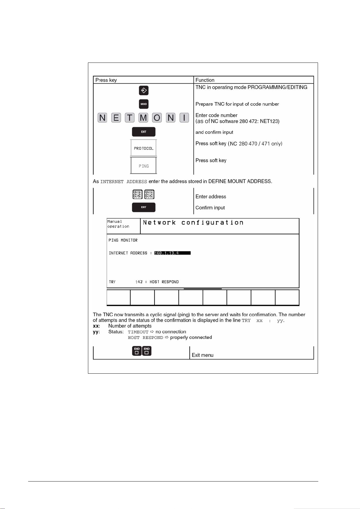
7.4 Checking the Connection to the Server
April 2010 7 – 79
Page 79

7.5 Finding the Hardware Address of the Ethernet Card
7 – 80 HEIDENHAIN Service Manual for Data Interfaces
Page 80

7.6 Working with the Ethernet Interface
7.6.1 Establish network connection (mount)
April 2010 7 – 81
Page 81

The network line must be connected to the Ethernet card.
On the left half of the screen the mounted drive is displayed; in the example:
7 – 82 HEIDENHAIN Service Manual for Data Interfaces
Page 82

7.6.2 Unmounting a network connection
April 2010 7 – 83
Page 83

7 – 84 HEIDENHAIN Service Manual for Data Interfaces
Page 84

8 Error Messages and their Causes
8.1 Error Messages Related to the RS-232C and RS-422 Interfaces
8.1.1 Error messages at the TNC in the ME mode
WRONG OPERATING MODE
No operating mode or wrong operating mode set on the
external data medium.
FAULTY PROGRAM DATA
Wrong or faulty program data have been detected during
data transfer. The control attempted three times to read from
the magnetic tape before aborting the process.
DATA MEDIUM MISSING
No cassette has been inserted into the drive.
DATA MEDIUM EMPTY
No programs are stored on the data medium (cassette).
DATA MEDIUM WRITE-PROTECTED
The write-enable plug in the cassette is missing.
PROGAM INCOMPLETE
Data transfer was aborted before the program was
completely loaded.
EXT. IN/OUTPUT NOT READY
The DSR signal is missing at the TNC.
- ME not connected
- Transmission cable defective or incorrect
- Wrong interface assignment
ME: TAPE END
The cassette is full. To continue data transfer, turn over or
exchange the cassette.
April 2010 8 – 85
Page 85

8.1.2 Error messages at the ME
DEL
STOP
In the ME, the electronics is tested and the external operating conditions are checked. If an error
is detected, the lamps of the operating mode display start blinking. In the table below the error
types are listed:
LED off
LED blinks
Indicator lamps Error message
Faulty data during transfer
No cassette inserted
Write-enable plug in cassette is missing
Wrong operating mode selected
Data of magnetic tape faulty
Magnetic tape empty
Error in ME electronics
End of tape
Peripheral unit is not connected
Data transfer between TNC and ME or peripheral interrupted by
Pressing clears the error messages.
8 – 86 HEIDENHAIN Service Manual for Data Interfaces
Page 86

8.1.3 Error messages at the FE in the ME mode
In the ME mode, errors are displayed by the indicator lamps (LEDs) of the control buttons
blinking.
LED off
LED on
LED blinks
Indicator lamps Error message
Disk is missing or error in the electronics
Disk cannot be formatted, as it is currently being used
Disk is missing or not formatted
Disk cannot be copied, as a read/write process is active
External device not ready or not connected
Disk is missing or not formatted
Disk is missing or not formatted or no program is available
Program cannot be output, as data transfer via the TNC interface is in
process
Program cannot be output, as data transfer via the PRT interface is in
process
External device not ready or not connected
Disk is missing or not formatted
Disk is missing or not formatted
Program cannot be output, as data transfer via the TNC interface is in
process
Program cannot be output, as data transfer via the PRT interface is in
process
External device not ready or not connected
Disk is missing or error in the electronics
Table of contents cannot be output, as data transfer via the PRT interface
is in process.
April 2010 8 – 87
Page 87

STOP
No interface coupling is possible, as data transfer via the TNC interface is
in process
No interface coupling is possible, as data transfer via the PRT interface is
in process
External device not ready or not connected
Pressing clears the error messages.
8 – 88 HEIDENHAIN Service Manual for Data Interfaces
Page 88

8.1.4 Error messages at the TNC in the FE mode
In this operating mode, the floppy disk unit outputs errors in the following format:
(SOH) ERR: (SP) (SP) (SP) [XXX] (ETB) (BCC)
XXX = Error number
The following errors may be displayed:
Input/Output Errors
ERR: 001 = Incorrect command code
ERR: 002 = Illegal program name
ERR: 003 = Faulty data transfer
ERR: 004 = Program incomplete
ERR: 005 = Receiving buffer overflow
ERR: 006 = Function currently disabled
ERR: 007 = Data-buffer overflow
Errors during Program Write or Read
ERR: 010 = Program not on disk
ERR: 011 = Program erase-protected
ERR: 012 = Program is being written to
ERR: 013 = Program directory is full
ERR: 014 = Disk is full
ERR: 015 = Text not found
ERR: 016 = Program name already exists
ERR: 017 = Disk access active
ERR: 018 = Program currently being read
Disk / Drive / Controller Errors
ERR: 100 = Disk not initialized
ERR: 101 = Sector number too large
ERR: 102 = Drive not ready 2)
ERR: 103 = Disk is write-protected
ERR: 104 = Faulty data on disk
ERR: 105 = Sector cannot be found 1)
ERR: 106 = Check sum is incorrect
ERR: 107 = Disk controller defective 3)
ERR: 108 = DMA error 3)
ERR: 109 = Disk exchanged during program loading
1)
These error messages indicate that the disk is defective; in most cases, they can only
be eliminated by reformatting the disk.
2)
If this error message comes up while the disk is inserted, the drive is probably defective.
3)
Hardware defect
1)
1)
1)
April 2010 8 – 89
Page 89

8.1.5 Error messages during data transfer
TRANSFERRED VALUE INCORRECT X
X = A Faulty character frame
B Character overflow
C Faulty character frame or character
overflow
D Parity error
E Faulty character frame or parity error
F Character overflow or parity error
G Faulty character frame or character
overflow or parity error
H Receiving buffer overflow
K Incorrect ESC sequence (only in "ME" mode)
L Incorrect ESC sequence (only in "ME" mode)
DATA TRANSFER ERRONEOUS X
X = A Faulty character frame
D Parity error
M The control has received the character for
"Negative Acknowledgement" (NAK) more
than 3 times
N The control has transmitted the character for
"Negative Acknowledgement" (NAK) more
than 3 times
P Timeout ACK/NAK
BAUD RATE NOT POSSIBLE
If both data interfaces (RS 232/RS 422) are active
simultaneously, the baud rate of both data interfaces must
be the same.
INTERFACE ALREADY ASSIGNED
A data interface cannot be used for two operating modes at
a time (e.g. DNC mode and simultaneous programming is not
possible with one data interface).
EXT. IN/OUTPUT NOT READY
- DSR signal missing at the TNC
- Transmission cable defective or incorrect
- Wrong interface assignment
PROGAM INCOMPLETE
Data transfer was aborted before the program was
completely loaded.
8 – 90 HEIDENHAIN Service Manual for Data Interfaces
Page 90

8.2 Ethernet Error Messages
ErrInternetor messages or warnings that are generated when a device is mounted, are stored in
plain language in an ERROR file.
When the control is switched off and on, the contents of this file is deleted.
The entries in this file can be viewed by entering the code number "NET123" and pressing the
soft key "SHOW ERROR".
Structure of an Error Message
A message starts with the program part that detected the error; this element is terminated by a
colon. Then the name of the device to be mounted can follow in <> angle brackets. The software
differentiates between errors (E) and warnings (W). In the event of an error the network cannot
be activated and the device cannot be mounted. When a warning is generated, the network
could be activated or the device mounted, however, inappropriate entry values were corrected.
Errors reported by the link layer:
LL: (W) CONNECTION "error string" UNKNOWN USING DEFAULT 10BASE2
An unknown name was entered for the connection.
10BASE2 (Thin Ethernet) is used.
LL: (E) PROTOCOL "error string" UNKNOWN
An unknown name was entered for the protocol.
Errors detected by the network layer:
IP4: (E) INTERFACE NOT PRESENT
The Ethernet card could not be found.
IP4: (E) INTERNET ADDRESS NOT VALID
The control was assigned an invalid Internet address; e.g. a class D or E address,
a loop-back address or a broadcast address.
IP4: (E) SUBNETMASK NOT VALID
The specified subnet mask does not match the Internet address, or only 1 bit
was provided for the subnet ID or the host ID.
IP4: (E) SUBNETMASK OR HOST ID NOT VALID
Input of Internet address or subnet mask faulty, or all bits of the host ID are 0 or 1.
IP4: (E) SUBNET MASK OR SUBNET ID NOT VALID
All bits of the SUBNET ID are 0 or 1.
IP4: (E) DEFAULTROUTERADRESS NOT VALID
For the default router an invalid Internet address was entered; e.g. a class D or E address,
a loop-back address or a broadcast address.
IP4: (E) CANNOT USE DEFAULT ROUTER
The net ID and the subnet ID of the default router are not identical to those of the control.
IP4: (E) I AM NOT A ROUTER
The Internet address of the default router is identical to that of the control.
Errors detected by the mount system call:
MOUNT: <Device name> (E) DEVICENAME NOT VALID
The device name is either too long or it contains illegal characters.
MOUNT: <Device name> (E) DEVICENAME ALREADY ASSIGNED
A device with the same name already exists
MOUNT: <Device name> (E) DEVICETABLE OVERFLOW
The device table is full; the device cannot be mounted any more.
April 2010 8 – 91
Page 91

Errors and warnings generated by the network file system, version 2:
NFS2: <Device name> (W) READSIZE SMALLER THEN x SET TO x
The selected read size is too small; it is set to the smallest permissible value.
NFS2: <Device name> (W) READSIZE LARGER THEN x SET TO x
The selected read size is too large; it is set to the highest permissible value.
NFS2: <Device name> (W) WRITESIZE SMALLER THEN x SET TO x
The selected write size is too small; it is set to the smallest permissible value.
NFS2: <Device name> (W) WRITESIZE LARGER THEN x SET TO x
The selected write size is too large; it is set to the highest permissible value.
NFS2: <Device name> (E) MOUNTPATH TOO LONG
The specified mount path is too long; the device cannot be mounted.
NFS2: <Device name> (E) NOT ENOUGH MEMORY
The memory available for the driver is insufficient to provide the management
data for the device.
NFS2: <Device name> (E) HOSTNAME TOO LONG
The specified host name is too long; the device cannot be mounted.
NFS2: <Device name> (E) CANNOT OPEN PORT
A port required for mounting cannot be opened.
NFS2: <Device name> (E) ERROR FROM PORTMAPPER
The data received from the port mapper are not plausible, or no data were received.
NFS2: <Device name> (E) ERROR FROM MOUNTSERVER
The data received from the mount server are not plausible, or no data were received.
NFS2: <Device name> (E) CANT GET ROOTDIRECTORY
The mount server does not permit the mounting of the specified directory.
NFS2: <Device name> (E) UID OR GID 0 NOT ALLOWED
User ID 0 and group ID 0 are not permitted; they may exclusively be used by the
super user or the system administrator.
8 – 92 HEIDENHAIN Service Manual for Data Interfaces
Page 92

9 Tables
9.1 7-Bit ASCII Code
Character Decimal Octal Hexadecimal
NUL 000 000 00
SOH 001 001 01
STX 002 002 02
ETX 003 003 03
EOT 004 004 04
ENQ 005 005 05
ACK 006 006 06
BEL 007 007 07
BS 008 010 08
HT 009 011 09
LF 010 012 0A
VT 011 013 0B
FF 012 014 0C
CR 013 015 0D
SO 014 016 0E
SI 015 017 0F
DLE 016 020 10
DC1 (X-ON) 017 021 11
DC2 018 022 12
DC3 (X-OFF) 019 023 13
DC4 020 024 14
NAK 021 025 15
SYN 022 026 16
ETB 023 027 17
CAN 024 030 18
EM 025 031 19
SUB 026 032 1A
ESC 027 033 1B
FS 028 034 1C
GS 029 035 1D
RS 030 036 1E
US 031 037 1F
April 2010 9 – 93
Page 93

Character Decimal Octal Hexadecimal
SP 032 040 20
! 033 041 21
“ 034 042 22
# 035 043 23
$ 036 044 24
% 037 045 25
& 038 046 26
’ 039 047 27
( 040 050 28
) 041 051 29
* 042 052 2A
+ 043 053 2B
, 044 054 2C
- 045 055 2D
. 046 056 2E
/ 047 057 2F
0 048 060 30
1 049 061 31
2 050 062 32
3 051 063 33
4 052 064 34
5 053 065 35
6 054 066 36
7 055 067 37
8 056 070 38
9 057 071 39
: 058 072 3A
; 059 073 3B
< 060 074 3C
= 061 075 3D
> 062 076 3E
? 063 077 3F
@ 064 100 40
A 065 101 41
B 066 102 42
C 067 103 43
9 – 94 HEIDENHAIN Service Manual for Data Interfaces
Page 94

Character Decimal Octal Hexadecimal
D 068 104 44
E 069 105 45
F 070 106 46
G 071 107 47
H 072 110 48
I 073 111 49
J 074 112 4A
K 075 113 4B
L 076 114 4C
M 077 115 4D
N 078 116 4E
O 079 117 4F
P 080 120 50
Q 081 121 51
R 082 122 52
S 083 123 53
T 084 124 54
U 085 125 55
V 086 126 56
W 087 127 57
X 088 130 58
Y 089 131 59
Z 090 132 5A
[ 091 133 5B
\ 092 134 5C
] 093 135 5D
^ 094 136 5E
_ 095 137 5F
` 096 140 60
a 097 141 61
b 098 142 62
c 099 143 63
d 100 144 64
e 101 145 65
f 102 146 66
g 103 147 67
April 2010 9 – 95
Page 95

Character Decimal Octal Hexadecimal
h 104 150 68
i 105 151 69
j 106 152 6A
k 107 153 6B
l 108 154 6C
m 109 155 6D
n 110 156 6E
o 111 157 6F
p 112 160 70
q 113 161 71
r 114 162 72
s 115 163 73
t 116 164 74
u 117 165 75
v 118 166 76
w 119 167 77
x 120 170 78
y 121 171 79
z 122 172 7A
{ 123 173 7B
| 124 174 7C
} 125 175 7D
~ 126 176 7E
DEL 127 177 7F
9 – 96 HEIDENHAIN Service Manual for Data Interfaces
Page 96

9.2 Powers of 2
n 2
01
12
24
38
416
532
664
7128
8256
9512
10 1 024
11 2 048
12 4 096
13 8 192
14 16 384
n
15 32 768
16 65 536
17 131 072
18 262 144
19 524 288
20 1 048 576
April 2010 9 – 97
Page 97

9 – 98 HEIDENHAIN Service Manual for Data Interfaces
Page 98

Page 99

Page 100

Mai 2006 HEIDENHAIN Service-Handbuch iTNC 530
 Loading...