


Instruction Manual
HI8931 • HI8936 Series
HI943500 Series
Conductivity Process
Controllers and Transmitters
w w w . h a n n a i n s t . c o m

Dear Customer,
Thank you for choosing a HANNA instruments® product.
Please read this instruction manual carefully before using the instrument.
This manual will provide you with all the necessary information for correct use of the instruments, as well as a precise idea of thier versatility in a wide range of applications.
If you need additional technical information, do not hesitate to e-mail us at tech@hannainst.com
These instruments are in compliance with the 
 directives.
TABLE OF CONTENTS |
|
Preliminary Examination ............................................................ |
4 |
General Description .................................................................... |
4 |
Functional Description HI 8931 & HI 943500 ............................ |
6 |
Functional Description HI 8936 ................................................ |
10 |
Conductivity Probes .................................................................. |
13 |
Specifications HI 8931 & HI 943500 ....................................... |
15 |
Specifications HI 8936 ............................................................. |
16 |
Connections .............................................................................. |
17 |
Operational Guide ................................................................... |
25 |
Calibration Procedure of HI 8931 & HI 8936 with HI 7635 .... |
31 |
Calibration Procedure of HI 8931 & HI 8936 with HI 7638 .... |
35 |
Calibration Procedure of HI 943500 with HI 7638 ................... |
39 |
Conductivity Versus Temperature Chart ..................................... |
41 |
Diagnostic Tests ........................................................................ |
42 |
Installation Examples ............................................................... |
44 |
Probe Maintenance and Cleaning ............................................ |
46 |
Accessories ................................................................................ |
47 |
Warranty ................................................................................. |
49 |
CE Declaration of Conformity ..................................................... |
50 |
2 |
3 |

PRELIMINARY EXAMINATION
Remove the instrument from the packing material and examine it carefully to make sure that no damage has occurred during shipping. If there is any noticeable damage, notify your dealer.
Each model is supplied complete with:
•Mounting brackets (not for HI 8936 series)
•Transparent splsh-proof cover (not for HI 8936 series)
•Instruction manual
Note: Save all packing materials until you are sure that the instrument functions correctly. All defective items must be returned in the original packing materials together with the supplied accessories.
GENERAL DESCRIPTION
The HI 8931 and HI 943500 are panel-mounted conductivity controllers designed for simplicity of use in a wide range of industrial process applications.
The instruments are designed with a standard DIN panel mount with membrane keypads and large LCD on the front, and provide a series of auto-diagnostic functions.
Probes, power supply, contacts and recorders are connected on the rear panel through screw terminals.
Using HI 8931 in conjunction with a 4-20 mA output transmitter (HI 8936 or HI 8936L series) will assure you of a strong, interferencefree signal at distances up to 300 meters (1000').
For in-line applications use the HI 7635 probe, while for tanks the HI 7638 with external threads is recommended. These probes are provided with built-in NTC sensor for temperature compensated conductivity measurements. The probe cable length is 3 meters (10').
HI 943500 features a direct connection up to 20 m (67'), without intermediate amplifiers, to the conductivity probe HI 7638 with DIN connector and automatic temperature compensation.
Four models with different measurement ranges are available to suit any application needs:
•HI 8931A / HI 943500A / HI8936A / HI8936AL from 0.0 to 199.9 mS/cm
•HI 8931B / HI 943500B / HI8936B / HI 8936BL from 0.00 to 19.99 mS/cm
•HI 8931C / HI 943500C / HI 8936C / HI8936CL from 0 to 1999 μS/cm
•HI 8931D / HI 943500D / HI 8936D / HI 8936DL from 0.0 to 199.9 μS/cm
Other features include: recorder output in 0-20 mA or 4-20 mA configuration; LED indicators (for HI 8931 and HI 943500) which identify whether the controller is in operation mode or selection mode.
Each instrument of the HI 8931 and HI 943500 series, is supplied with a plastic front cover and two mounting brackets. Power cables are not included.
4 |
5 |

FUNCTIONAL DESCRIPTION
HI 8931 & HI 943500
|
|
|
|
|
|
|
|
|
|
|
|
|
|
|
|
|
|
|
|
|
|
|
|
|
|
|
|
|
|
|
|
|
|
|
|
|
|
|
|
|
|
|
|
|
|
|
|
|
|
|
|
|
|
|
|
|
|
|
|
|
|
|
|
|
|
|
|
|
|
|
|
|
|
|
|
|
|
|
|
|
|
|
|
|
|
|
|
|
|
|
|
|
|
|
|
|
|
|
|
|
|
|
|
|
|
|
|
|
|
|
|
|
|
|
|
|
|
|
|
|
|
|
|
|
|
|
|
|
|
|
|
|
|
|
|
|
|
|
|
|
|
|
|
|
|
|
|
|
|
|
|
|
|
|
|
|
|
|
|
|
|
|
|
|
|
|
|
|
|
|
|
|
|
|
|
|
|
|
|
|
|
|
|
|
|
|
|
|
|
|
|
|
|
|
|
|
|
|
|
|
|
|
|
|
|
|
|
|
|
|
|
|
|
|
|
|
|
|
|
|
|
|
|
|
|
|
|
|
|
|
|
|
|
|
|
|
|
KEYPAD |
|
|
|
|
|
|
|
|
|
|
|
|
|
|
||
MEASURE |
To read measurements and enable diagnostic tests |
|||||||||||||||
AL |
To display set tolerance of the alarm |
|||||||||||||||
SET |
To set working point |
|||||||||||||||
TESTSLOPE |
Diagnosticfunction |
|||||||||||||||
TESTOFFSET |
Diagnosticfunction |
|||||||||||||||
When a key is pressed, the corresponding LED lights up to indicate that the function is active.
TRIMMERS |
|
OFFSET |
For offset calibration |
SLOPE |
For slope calibration |
AL |
To set the alarm tolerance |
COARSE |
To coarsely adjust the set point |
SET FINE |
To finely adjust the set point |
LEDS |
|
SET ON |
To indicate that the dosage is active |
ALARM |
To indicate an alarm condition |
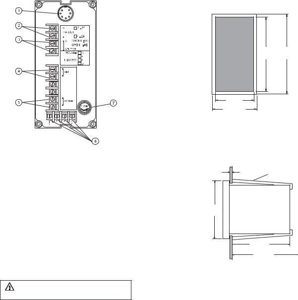
REAR PANEL OF HI 8931 SERIES
1.POWER OUTPUT terminals (+20 V and COM) for connection to a conductivity transmitter (HI 8936)
2.mA INPUT from a conductivity transmitter
3.mA OUTPUT terminals for connection to a recorder
4.SET SELECT terminals for reverse control operation
5.SET terminals for connection to a dosing pump
6.ALARM terminals for connection to an external alarm device
7.Power supply terminals
8.Fuse holder
Unplug the instrument from power supply before replacing the fuse.
6 |
7 |
REAR PANEL OF HI 943500 SERIES
1.DIN connector for conductivity probe
2.mA OUTPUT terminals for connection to a recorder
3.SET SELECT terminals for reverse control operation
4.SET terminals for connection to a dosing pump
5.ALARM terminals for connection to an external alarm device
6.Power supply terminals
7.Fuse holder
Unplug the instrument from power supply before replacing the fuse.
MECHANICAL DIMENSIONS
OF HI 8931 AND HI 943500
Front view of the panel-mounted unit
141mm 144mm 5.55" 5.67"
69mm
2.71"
72mm
2.83"
These dimensions show the cutout size for the installation.
Side view of the panel-mounted unit
0.25/4mm ADJUSTABLE
0.01/0.160" LOCATION BRACKET
144mm
5.67"
135mm
5.31"
190mm MIN
7.50"
Adjustable location brackets (supplied with the meter) allow the indicator to slide into the cutout and will hold the unit securely in place. 190 mm (7.50") is the minimum amount of room required to install the indicator with the cables connected.
8 |
9 |
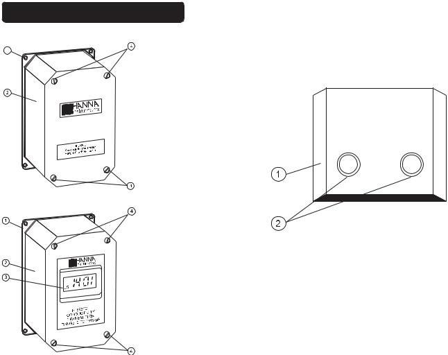
FUNCTIONAL DESCRIPTION HI 8936
HI 8936A
HI 8936B
HI 8936C
HI 8936D
HI 8936AL
HI 8936BL
HI 8936CL
HI 8936DL
1.Back cover
2.Top cover
3.Liquid Crystal Display
4.Screws for fastening the top cover
SIDE VIEW OF HI 8936 SERIES
1.Top cover
2.Cable glands for wiring
10 |
11 |

MECHANICAL DIMENSIONS OF
HI 8936A, HI8936B, HI8936C, HI8936D
165mm
6.50"
8614 |
100mm |
110mm |
3.94" |
4.33" |
|
|
|
|
HI |
|
|
|
4 x 4.3mm |
|
|
|
|
|
|
90mm |
4 x 0.17" |
|
155mm |
|
|||
|
6.10" |
||
3.54" |
|
|
|
MECHANICAL DIMENSIONS OF
HI 8936AL, HI8936BL, HI 8936CL, HI8936DL
165mm |
|
6.50" |
126mm |
|
|
58mm |
5.00" |
|
|
2.28" |
|
24mm |
|
0.94" |
|
45mm |
8614L |
100mm |
110mm |
|
1.77" |
3.94" |
4.33" |
||
|
||||
|
HI |
|
|
|
4 x 4.3mm |
155mm |
|
|
|
4 x 0.17" |
|
|
||
90mm |
6.10" |
|
|
|
3.54" |
|
|
|
CONDUCTIVITY PROBES
HI 7635 In-line Conductivity Probe
HI 7635 is a one piece, molded conductivity probe with pipe threads (1" NPT) at both ends.
This allows the probe to attach to an in-line system, and to be used in conjunction with the HI 8936 conductivity transmitter.
The HI 7635 uses a 4-ring potentiometric measuring method. This method is highly accurate and requires very little maintenance.
The construction of the housing is rugged, fiber-reinforced polypropylene.
The maximum working pressure of this unit is 5 bar (72.5 psi). Do not use in systems where the temperature exceeds 80°C (176°F).
HI7635
142mm |
52mm |
5.60" |
2.04" |
|
73mm |
|
2.87" |
|
1" NPT |
12 |
13 |

HI7638 Tank Conductivity Probe
HI 7638 conductivity probe combines the proven 4-ring potentiometric method of measuring conductivity with the platinum sensor and stainless steel external thread.
This method incorporates a series of four platinum rings into the probe shaft and is highly accurate requiring very little maintenance.
The removable plastic cover resists the harmful effect of most chemicals and can be unscrewed for quick and simple maintenance.
This probe can withstand temperatures of up to 120°C (248°F) and pressure of up to 5 bar (72.5 psi).
This probe is supplied complete with a 7-pin DIN connector.
HI 7638
SPECIFICATIONS |
HI 8931 |
& |
HI 943500 |
|
|
|
|
Range |
|
|
|
HI 8931A - HI 943500A |
0.0 to 199.9 mS/cm |
||
HI 8931B - HI 943500B |
0.00 to 19.99 mS/cm |
||
HI 8931C - HI 943500C |
0 to 1999 μS/cm |
||
HI 8931D - HI 943500D |
0.0 to 199.9 μS/cm |
||
Accuracy |
±2% of Full Scale |
||
(@20°C/68°F) |
excluding probe error |
||
Typical EMC |
±2.5% of Full Scale |
||
Deviation |
|
±0.4 mA |
|
4-20mA INPUT from |
|
|
|
Transmitter |
|
|
|
HI 8931A |
HI 8936 A or AL (not included) |
||
HI 8931B |
HI 8936 B or BL (not included) |
||
HI 8931C |
HI 8936 C or CL (not included) |
||
HI 8931D |
HI 8936 D or DL (not included) |
||
HI 943500 |
|
|
------ |
Conductivity Probe |
HI 7635 for in-line applications or |
||
|
HI 7638 for tank (not included) |
||
Calibration |
Manual, |
2 |
point, through |
|
offset and slope trimmers |
||
|
|
|
|
Temp. Compensation |
|
|
|
HI 8931 |
See transmitter HI 8936 |
||
HI 943500 |
Automatic, 0 to 60°C with ß=2% |
||
Recorder Output |
4 to 20 mA (isolated) |
||
Set Point Relay and |
Isolated, 2A, Max. 240V, resistive |
||
Alarm Relay |
load, 1,000,000 strokes |
||
Power Supply |
115 or 230 Vac ±10% |
||
|
(user selectable); 50/60 Hz |
||
Environment |
-10 to 50°C (14 to 122°F); RH 95% |
||
Panel Cutout |
141 x 69 mm (5.6 x 2.7") |
||
Weight |
1 kg (2.2 lb.) |
||
Enclosure |
DIN 43 700, 144x72 mm (5.7x2.8"), |
||
|
black anodized aluminum; |
||
|
front and back with shockproof ABS |
||
|
plastic, and |
transparent cover |
|
|
|
|
|
14 |
15 |

SPECIFICATIONS HI 8936
Range |
|
HI 8936 A/AL |
0.0 to 199.9 mS/cm |
HI 8936 B/BL |
0.00 to 19.99 mS/cm |
HI 8936 C/CL |
0 to 1999 μS/cm |
HI 8936 D/DL |
0.0 to 199.9 μS/cm |
|
|
Accuracy |
±2% of Full Scale |
(@20°C/68°F) |
excluding probe error |
Typical EMC |
±2% of Full Scale |
Deviation |
±0.4 mA |
Conductivity Probe |
HI 7635 for in-line applications or |
|
HI 7638 for tank (not included) |
|
|
Calibration |
Manual, 2 point, through |
|
offset and slope trimmers |
Temperature |
Fixed or automatic |
Compensation |
from 0 to 50°C (32 to 122°F) |
|
with ß=2% |
Output |
4 to 20 mA not-isolated |
|
max. 500 Ohm |
Power Supply |
|
HI 8936 A/B/C/D |
12 to 30 Vdc |
HI 8936 AL/BL/CL/DL |
17 to 36 Vdc |
Protection |
IP 65 |
Environment |
0 to 50°C (32 to 122°F); |
|
RH max 95% |
Dimensions |
165 x 110 x 90 mm |
|
(6.5 x 4.3 x 3.5") |
Weight |
1 kg (2.2 lb.) |
|
|
CONNECTIONS
REAR CONNECTIONS FOR HI 8931
• Power Connection Terminals
4-screw-terminal-strip for connection to a 3-wire power cable according to the indicated voltage (115 or 230V).
• IN/OUT Transmitter
2 wires of the 4-core signal cable from the conductivity transmitter (HI8936) have to be connected to the mA input terminals and the other 2 wires to the "+20 V" and "COM" while paying careful attention to the polarity.
+20 V supply is the regulated DC supply required for the operation of the external conductivity transmitter HI 8936.
• Set Contacts
Dosing pumps or other control equipment may be connected to the "SET" (Max. 2A, 240 V) terminals. These contacts act only as a "dry" switch allowing electrical continuity, not as a power supply.
16 |
17 |
 Loading...