


pH 502/mV 602 Series
Panel-mounted,
Microprocessor-based
Process pH/mV Meters
Instruction Manual
Dear Customer,
Thank you for choosing a Hanna Product.
Please read this instruction manual carefully before using the instrument. It will provide you with the necessary information for the correct use of the instrument, as well as a precise idea of its versatility.
If you need additional technical information, do not hesitate to e-mail us at tech@hannainst.com.
These instruments are in compliance with the 
 directives.
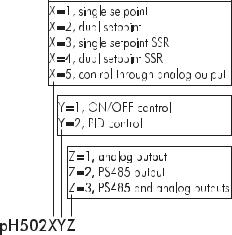
MODEL IDENTIFICATION
The models pH502XYZ are pH controllers, while the models mV602XYZ are ORP controllers.
The meaning of the last three letters is according to the following scheme:
© 1999 Hanna Instruments
All rights are reserved. Reproduction in whole or in part is prohibited without the written consent of the copyright owner, Hanna Instruments Inc., 584 Park East Drive, Woonsocket, Rhode Island, 02895 , USA.
2

TABLE OF CONTENTS
PRELIMINARY EXAMINATION . . . . . . . . . . . . . . . . . . 4 GENERAL DESCRIPTION . . . . . . . . . . . . . . . . . . . . . 4 FUNCTIONAL DESCRIPTION . . . . . . . . . . . . . . . . . . 6 MECHANICAL DIMENSIONS . . . . . . . . . . . . . . . . . . 7 SPECIFICATIONS pH 502 & mV 602 . . . . . . . . . . . . . 8 INSTALLATION . . . . . . . . . . . . . . . . . . . . . . . . . . . . 9 SETUP MODE . . . . . . . . . . . . . . . . . . . . . . . . . . . . 11 CONTROL MODE . . . . . . . . . . . . . . . . . . . . . . . . . 17 IDLE MODE . . . . . . . . . . . . . . . . . . . . . . . . . . . . . 25 ANALOG OUTPUT . . . . . . . . . . . . . . . . . . . . . . . . 26 RS 485 COMMUNICATION . . . . . . . . . . . . . . . . . . 28 CALIBRATION . . . . . . . . . . . . . . . . . . . . . . . . . . . . 35 LAST CALIBRATION DATA . . . . . . . . . . . . . . . . . . . . 48 STARTUP . . . . . . . . . . . . . . . . . . . . . . . . . . . . . . . 51 FAULT CONDITIONS AND SELFTEST PROCEDURES . . 52 pH VALUES AT VARIOUS TEMPERATURES . . . . . . . . . 56 ELECTRODE CONDITIONING AND MAINTENANCE . . 57 TAKING REDOX MEASUREMENTS. . . . . . . . . . . . . . 61 ACCESSORIES . . . . . . . . . . . . . . . . . . . . . . . . . . . 63 WARRANTY . . . . . . . . . . . . . . . . . . . . . . . . . . . . . 69 CE DECLARATION OF CONFORMITY . . . . . . . . . . . 70
3

PRELIMINARY EXAMINATION
Remove the instrument from the packing material and examine it carefully to make sure that no damage has occurred during shipping. If there is any noticeable damage, notify your Dealer or the nearest Hanna Customer Service Center immediately.
Note Save all packing materials until you are sure that the instrument functions correctly. Any damaged or defective items must be returned in their original packing materials together with the supplied accessories.
GENERAL DESCRIPTION
The product is a real time microprocessor-based pH/ORP controller. It provides accurate measurements, flexible ON/OFF or PID control capabilities and dual alarm signals.
The system is composed of a case inside which the signal conversion circuitry, the microprocessor circuitry and the output power drivers are contained.
MAIN FEATURES OF DIFFERENT MODELS
•Display: large LCD with 4 ½ 17 mm digits and 3 ½ 10 mm digits.
•LEDs: three (mV 602) or four (pH 502) LEDs are provided for signaling the energizing of relay 1 (a yellow LED), relay 2 (a yellow LED in pH 502 Series only) and alarm relays (a green and a red LED).
•Relays: 1 or 2 output relays for acid or base dosage.
The models with Electromechanical Relay(s) have COM, NO and NC contacts. The models with Solid State Relay(s) have COM and NO contacts.
1 output relay for alarm condition (COM, NO and NC contacts).
•RS485 isolated communication link (optional).
•Calibration and Setup procedures allowed only through an unlock password.
•Calibration: for pH 502 Series in 1, 2 or 3 points with buffers 4.01, 7.01 and 10.01 pH (25 °C); for mV 602
4
Series in 1 or 2 points at 0, 350 and 1900 mV.
•Temperature compensation of the HANNA standard buffers (for pH 502 Series only).
•Temperature compensation of the pH reading (for pH 502 Series only).
•Manual temperature setting when the temperature probe is not inserted or temperature exceeds the upper range.
•Last calibration data internally recorded (non-volatile EEPROM memory): calibration date and time, pH offset, pH slopes, number of calibration points and correspondent pH values (for pH 502 Series only) or calibration date and time and the mV calibration points used (for mV 602 Series only).
•Input: pH electrode with BNC connector.
•±5 VDC output for amplified electrodes.
•Output:
-isolated 0-1 mA, 10 KΩ maximum load (optional);
-isolated 0-20 mA, 750 Ω maximum load (optional);
-isolated 4-20 mA, 750 Ω maximum load (optional);
-isolated 0-5 VDC, 1 KΩ minimum load (optional);
-isolated 1-5 VDC, 1 KΩ minimum load (optional);
-isolated 0-10 VDC, 1 KΩ minimum load (optional).
•Real time clock.
5
FUNCTIONAL DESCRIPTION
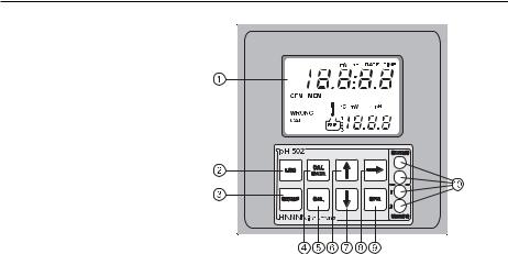
FRONT PANEL
|
|
|
|
|
|
|
1. |
Liquid Crystal Display |
|||||
2. |
LCD key |
exits from setup and calibration modes and reverts back to |
||||
|
|
normal mode (in idle or control phases with the measure- |
||||
|
|
ment on the display). In pH 502 series, during pH |
||||
|
|
calibration, alternately displays pH buffer value or current |
||||
|
|
temperature |
||||
3. |
SETUP key |
enters setup mode |
||||
4. |
CAL DATA key |
last calibration data viewing (enters and exits) |
||||
5. |
CAL key |
initiates and exits calibration mode |
||||
6. |
key |
increases the blinking digit/letter by one when selecting a |
||||
|
|
parameter. Advances forward while in last calibration data |
||||
|
|
viewing mode. Increases the temperature setting when |
||||
|
|
temperature probe is not inserted |
||||
7. |
key |
decreases the blinking digit/letter by one when selecting a |
||||
|
|
parameter. Reverts backward while in last calibration data |
||||
|
|
viewing mode. Decreases the temperature setting when |
||||
|
|
temperature probe is not inserted |
||||
8. |
key |
moves to the next digit/letter (circular buffer) when select- |
||||
|
|
ing a parameter. Same as key during last calibration |
||||
|
|
data viewing mode |
||||
9. |
CFM key |
confirms current choice (and skips to the next item) |
||||
10. |
LEDs |
|
|
|
|
|
6
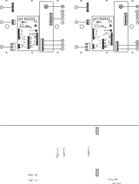
REAR PANEL |
|
|
|
|
|
|
|
|
|
|
|
|
|
|
|
|
|
|
|
|
|
|
|
|
|
|
|
|
|
||||||||||||||||||||||||
|
|
|
|
|
Models with 3-contact |
|
|
|
Models with 2-contact |
|
|
||||||||||||||||||||||||||||||||||||||||||
|
electromechanical output relay(s) |
|
|
|
solid state output relay(s) |
|
|
||||||||||||||||||||||||||||||||||||||||||||||
|
|
|
|
|
|
|
|
|
|
|
|
|
|
|
|
|
|
|
|
|
|
|
|
|
|
|
|
|
|
|
|
|
|
|
|
|
|
|
|
|
|
|
|
|
|
|
|
|
|
|
|
|
|
|
|
|
|
|
|
|
|
|
|
|
|
|
|
|
|
|
|
|
|
|
|
|
|
|
|
|
|
|
|
|
|
|
|
|
|
|
|
|
|
|
|
|
|
|
|
|
|
|
|
|
|
|
|
|
|
|
|
|
|
|
|
|
|
|
|
|
|
|
|
|
|
|
|
|
|
|
|
|
|
|
|
|
|
|
|
|
|
|
|
|
|
|
|
|
|
|
|
|
|
|
|
|
|
|
|
|
|
|
|
|
|
|
|
|
|
|
|
|
|
|
|
|
|
|
|
|
|
|
|
|
|
|
|
|
|
|
|
|
|
|
|
|
|
|
|
|
|
|
|
|
|
|
|
|
|
|
|
|
|
|
|
|
|
|
|
|
|
|
|
|
|
|
|
|
|
|
|
|
|
|
|
|
|
|
|
|
|
|
|
|
|
|
|
|
|
|
|
|
|
|
|
|
|
|
|
|
|
|
|
|
|
|
|
|
|
|
|
|
|
|
|
|
|
|
|
|
|
|
|
|
|
|
|
|
|
|
|
|
|
|
|
|
|
|
|
|
|
|
|
|
|
|
|
|
|
|
|
|
|
|
|
|
|
|
|
|
|
|
|
|
|
|
|
|
|
|
|
|
|
|
|
|
|
|
|
|
|
|
|
|
|
|
|
|
|
|
|
|
|
|
|
|
|
|
|
|
|
|
|
|
|
|
|
|
|
|
|
|
|
|
|
|
|
|
|
|
|
|
|
|
|
|
|
|
|
|
|
|
|
|
|
|
|
|
|
|
|
|
|
|
|
|
|
|
|
|
|
|
|
|
|
|
|
|
|
|
|
|
|
|
|
|
|
|
|
|
|
|
|
|
|
|
|
|
|
|
|
|
|
|
|
|
|
|
|
|
|
|
|
|
|
|
|
|
|
|
|
|
|
|
|
|
|
|
|
|
|
|
|
|
|
|
|
|
|
|
|
|
|
|
|
|
|
|
|
|
|
|
|
|
|
|
|
|
|
|
|
|
|
|
|
|
|
|
|
|
|
|
|
|
|
|
|
|
|
|
|
|
|
|
|
|
|
|
|
|
|
|
|
|
|
|
|
|
|
|
|
|
|
|
|
|
|
|
|
|
|
|
|
|
|
|
|
|
|
|
|
|
|
|
|
|
|
|
|
|
|
|
|
|
|
|
|
|
|
|
|
|
|
|
|
|
|
|
|
|
|
|
|
|
|
|
|
|
|
|
|
|
|
|
|
|
|
|
|
|
|
|
|
|
|
|
|
|
|
|
|
|
|
|
|
|
|
|
|
|
|
|
|
|
|
|
|
|
|
|
|
|
|
|
|
|
|
|
|
|
|
|
|
|
|
|
|
|
|
|
|
|
|
|
|
|
|
|
|
|
|
|
|
|
|
|
|
|
|
|
|
|
|
|
|
|
|
|
|
|
|
|
|
|
|
|
|
|
|
|
|
|
|
|
|
|
|
|
|
|
|
|
|
|
|
|
|
|
|
|
|
|
|
|
|
|
|
|
|
|
|
|
|
|
|
|
|
|
|
|
|
|
|
|
|
|
|
|
|
|
|
|
|
|
|
|
|
|
|
|
|
|
|
|
|
|
|
|
|
|
|
|
|
|
|
|
|
|
|
|
|
|
|
|
|
|
|
|
|
|
|
|
|
|
|
|
|
|
|
|
|
|
|
|
|
|
|
|
|
|
|
|
|
|
|
|
|
|
|
|
|
|
|
|
|
|
|
|
|
|
|
|
|
|
|
|
|
|
|
|
|
|
|
|
|
|
|
|
|
|
|
|
|
|
|
|
|
|
|
|
|
|
|
|
|
|
|
|
|
|
|
|
|
|
|
|
|
|
|
|
|
|
|
|
|
|
|
|
|
|
|
|
|
|
|
|
|
|
|
|
|
|
|
|
|
|
|
|
|
|
|
|
|
|
|
|
|
1.6-pin RS485 terminal (not for pH502XY1 and mV602XY1)
2.Analog output (not for pH502XY2 and mV602XY2)
3.Power supply input
4.Alarm terminal
5.Relay 2 - second dosing terminal (pH5022XY and pH5024XY models only)
6.Relay 1 - first dosing terminal
7.Connections for Pt 100 temperature sensor
8.Connection for electrode reference
9.Connection for Potential Matching Pin
10.BNC Socket for pH or ORP electrode
11.±5V power supply output
 Unplug the meter before starting any electrical connections.
MECHANICAL DIMENSIONS
|
|
|
|
|
|
|
|
|
|
|
|
|
|
|
|
|
|
|
|
|
|
|
|
|
|
|
|
|
|
|
|
|
|
|
|
|
|
|
|
|
|
|
|
|
|
|
|
|
|
|
|
|
|
|
|
|
|
|
|
|
|
|
|
|
|
|
|
|
|
|
|
|
|
|
|
|
|
|
|
|
|
|
|
|
|
|
|
|
|
|
|
|
|
|
|
|
|
|
|
|
|
|
|
|
|
|
|
|
|
|
|
|
|
|
FRONT VIEW |
|
|
|
|
|
|
|
|
|
|
|
|
|
|
SIDE VIEW |
|
|
7

SPECIFICATIONS pH 502 & mV 602
Range |
0.00-14.00 pH (pH 502 Series only) |
|
±2000 mV (mV 602 Series only) |
|
-9.9 to 120.0 °C |
|
|
Resolution |
0.01 pH (pH 502 Series only) |
|
1 mV (mV 602 Series only) |
|
0.1 °C |
|
|
Accuracy |
±0.02 pH (pH 502 Series only) |
(@20°C/68°F) |
±2 mV (mV 602 Series only) |
|
±0.5 °C |
|
|
Typical EMC Deviation |
±0.2 pH (pH 502 Series only) |
|
±10 mV (mV 602 Series only) |
|
±0.5 °C |
|
|
Installation Category |
II |
|
|
Power Supply |
230 ±10% VAC or 115 ±10% VAC, 50/60 Hz |
|
|
Power Consumption |
15 VA |
|
|
Over Current Protection |
400 mA 250V FAST FUSE |
|
|
Max. Oscillation Frequency |
4 MHz |
|
|
Relays 1 and 2 |
• Electromechanical relay SPDT contact outputs, |
|
5A-250 VAC, 5A - 30 VDC (resistive load) |
|
(pH 5021YZ, pH 5022YZ and mV 6022YZ) |
|
Fuse protected: 5A, 250V FUSE |
|
• SSR (Solid State Relay) 1A - 250VAC (pH 5023YZ , |
|
pH 5024YZ and mV 6023YZ) |
|
Fuse protected: 2A, 250V FAST FUSE |
|
|
Alarm Relay |
Electromechanical Relay SPDT contact output, |
|
5A - 250 VAC, 5A - 30 VDC (resistive load) |
|
Fuse protected: 5A, 250V FUSE |
|
|
Environment |
0-50 °C; max 85% R.H. non-condensing |
|
|
Enclosure |
single case ½ DIN |
|
|
Weight |
approximately 1.6 kg. (3.5 lb.) |
|
|
8

INSTALLATION
pH 502 and mV 602 offer a multitude of possibilities, from single and dual setpoints to ON/OFF or PID dosage, isolated outputs with user-selectable zoom, bi-directional RS485, recorder outputs in mAmps and Volts.
In addition, pH 502 and mV 602 are both equipped with the exclusive differential input.
In a system with poor grounding, it is possible to have a ground current flowing through the reference junction. This can cause a rapid degradation of the electrode. The Hanna differential input reduces the likelihood of ground loops.
See the diagram for a recommended installation.
9
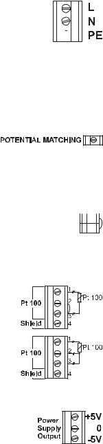
• Power Supply: Connect a 3-wire power cable to the terminal strip, while paying attention
to the correct line (L), earth (PE) and neu-
tral (N) terminal connections.  Power: 115VAC - 100 mA / 230VAC - 50 mA.
Line Contact: fused inside 400mA.
PE must be connected to ground; leakage current 1mA.
•Electrode: Connect the pH or ORP electrode to the BNC socket (#10 at page 7).
To benefit from the differential input, connect the proper electrode wire (if available) or a cable with a potential matching pin (grounding
bar) to the relevant terminal (#9 at page 7).
Note When it is not possible to immerse the Potential Matching Pin together with the pH electrode in the solution, disable the differential input by connecting the Connection for Potential Matching Pin (#9 page 7) with the Connection for Electrode Reference (#8 on page 


 7) with a jumper wire.


•Pt 100 Terminals: these contacts (#7 at page 7) connect the Pt 100 temperature sensor for automatic temperature compensation of pH measurement. In the case of shielded wire, connect the shield to pin 4.
In the case of a 2-wire sensor con-
nect the Pt 100 to pins 1 and 3, and short pins 2 and 3 with a jumper wire.
If the Pt 100 has more than 2
wires, connect the two wires of one end to pins 2 and 3 (pin 2 is an auxiliary input to compensate for
the cable resistance) and one wire from the other end to pin 1. Leave
the fourth wire unconnected, if present.
• Power Supply Output: these terminals provide +5V and -5V DC signals to supply power to amplified electrodes.
Note All cables connected to rear panel should end with cable lugs.
10
SETUP MODE
pH 502 and mV 602 offer a multitude of possibilities from ON/OFF or PID dosage to analog recorder output and from alarm to selftest features.
The Setup Mode allows the user to set all needed characteristics of the meter.
The setup mode is entered by pressing SETUP and entering the password when the device is in idle or control mode.
Generally speaking, if the password is not inserted the user can only view the setup parameters (except for password) without modifying them (and the device remains in control mode). An exception is certain setup items, or flags, which can activate special tasks when set and confirmed.
Each setup parameter (or setup item) is assigned a twodigit setup code which is entered and displayed on the secondary LCD.
The setup codes can be selected after password and CFM are pressed. When CFM is pressed, the current setup item is saved on EEPROM and the following item is displayed. Whenever LCD is pressed, the de-
vice reverts back to control mode. The same is true when CFM is
pressed on the last setup item.
The possible transitions in setup mode are the following:
ENTERING THE PASSWORD
•Press SETUP to enter the setup mode. The LCD will display “0000” on the upper part and “PAS” on the lower. The first digit of the upper part of the LCD will blink.
•Enter the first value of the pass-
word by the or keys.
11
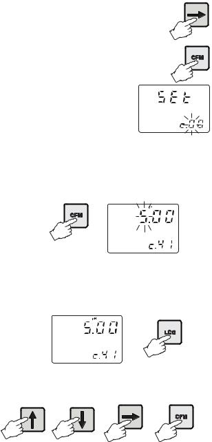
• Then confirm the displayed digit withand move to the next one.
• When the whole password has been inserted, press CFM to confirm it.
Note The default password is set at “0000”.
• The LCD will display “SET” on the upper part and “c.00” on the lower, allowing the user to edit setup parameters (see table below).
•Enter the code of the parameter you want to set, using the arrow keys as per the password procedure above (e.g. 41).
•Confirm the code by pressing CFM and the default or the previously memorized value will be displayed with the first digit blinking.
Note When the password is not inserted or a wrong password is confirmed, the display will only show the previously memorized value, without blinking (read only mode). In this case, the value cannot be set. Press LCD and start again.
•Enter the desired value using the arrow keys and then press CFM.
12

• Afterconfirmation,theselectedparameter is displayed. The user can scroll throughtheparametersbypressingCFM.
In order to directly set another parameter, press SETUP again and enter the code or scroll to it by pressing CFM.
The following table lists the setup codes along with the description of the specific setup items, their valid values and whether password is required to view that item (“PW” column):
Code |
Valid Values |
Default |
PW |
|
|
|
|
|
|
00 |
Factory ID |
0 to 9999 |
0000 |
no |
|
|
|
|
|
01 |
Process ID |
0 to 9999 (modelsw/o RS485) |
0000 |
no |
|
|
0 to 99 (models with RS485) |
00 |
no |
|
|
|
|
|
02 |
Control enable/disable |
0: C.M. disabled |
0 |
no |
|
|
1: C.M. enabled |
|
|
|
|
|
|
|
11 |
Relay 1 mode |
0: disabled |
0 |
no |
|
(M1) |
1: ON-OFF high setpoint |
|
|
|
|
2: ON-OFF low setpoint |
|
|
|
|
3: PID, high setpoint |
|
|
|
|
4: PID, low setpoint |
|
|
for pH 5025YZ and mV 6025YZ only:
0:disabled
1:PID, high setpoint
2:PID, low setpoint
12 |
Relay 1 setpoint |
0.00 to 14.00 pH |
8.00 pH |
no |
|
(S1) |
-2000 to 2000 mV |
500 mV |
|
|
|
|
|
|
13 |
Relay 1 hysteresis |
0.00 to 14.00 pH |
1 pH |
no |
|
(H1) |
0 to 4000 mV |
50 mV |
|
|
|
|
|
|
14 |
Relay 1 deviation |
0.50 to 14.00 pH |
1 pH |
no |
|
(D1) |
25 to 4000 mV |
50 mV |
|
|
|
|
|
|
15 |
Relay 1 reset time |
0.1 to 999.9 minutes |
999.9 mins |
no |
|
|
|
|
|
16 |
Relay 1 rate time |
0.0 to 999.9 minutes |
0.0 mins |
no |
|
|
|
|
|
21* |
Relay 2 mode (M2) |
same as relay 1 |
0 |
no |
|
|
|
||
* Available only in models with two relays |
|
|
||
13

Code |
Valid Values |
Default |
PW |
|
|
|
|
|
|
22* |
Relay 2 setpoint (S2) |
0.00 to 14.00 pH |
6.00 pH |
no |
|
|
-2000 to 2000 mV |
-500 mV |
|
|
|
|
|
|
23* |
Relay 2 hysteresis (H2) |
0.00 to 14.00 pH |
1 pH |
no |
|
|
0 to 4000 mV |
50 mV |
|
|
|
|
|
|
24* |
Relay 2 deviation (D2) |
0.50 to 14.00 pH |
1 pH |
no |
|
|
25 to 4000 mV |
50 mV |
|
|
|
|
|
|
25* |
Relay 2 reset time |
0.1 to 999.9 minutes |
999.9 mins |
no |
|
|
|
|
|
26* |
Relay 2 rate time |
0.0 to 999.9 minutes |
0.0 mins |
no |
|
|
|
|
|
30 |
Relay 3 high alarm (HA) |
0.00 to 14.00 pH |
9.00 pH |
no |
|
-2000 to 2000 mV |
600 mV |
|
|
|
|
HA>LA, HA>S1 or HA>S2 |
|
|
|
|
|
|
|
31 |
Relay 3 low alarm (LA) |
0.00 to 14.00 pH |
5.00 pH |
no |
|
|
-2000 to 2000 mV |
-600 mV |
|
|
|
LA<HA, LA<S1 or LA<S2 |
|
|
|
|
|
|
|
32 |
Proportional control |
1 to 30 min (models w/o SSR) |
5 min |
no |
|
mode period |
5 s to 30 min (models with SSR) 30 s |
no |
|
|
|
|
|
|
33 |
Maximum relay ON time |
1 to 60 min |
60 |
no |
|
(after which an alarm mode is entered) |
|
|
|
|
|
|
|
|
34 |
Alarm mask time |
00:00 to 30:00 (mm:ss) |
00:00 |
no |
|
|
|
|
|
40 |
Analog output selection |
0: 0-1mA |
2 |
no |
|
|
1: 0-20 mA |
|
|
|
|
2: 4-20 mA |
|
|
|
|
3: 0-5 VDC |
|
|
|
|
4: 1-5 VDC |
|
|
|
|
5: 0-10 VDC |
|
|
|
|
|
|
|
41 |
Analog output |
0.00 to 13.00 pH |
0.00 pH |
no |
|
lower limit |
-2000 to 2000 mV |
-2000 mV |
|
|
(O_VARMIN) |
(O_VARMIN < O_VARMAX-(1.00pH or 50mV)) |
||
|
|
|
|
|
42 |
Analog output |
1.00 to 14.00 pH |
14.00 pH |
no |
|
upper limit |
-2000 to 2000 mV |
2000 mV |
|
|
(O_VARMAX) |
(O_VARMIN < O_VARMAX- (1.00pH or 50mV)) |
||
|
|
|
|
|
14

Code |
Valid Values |
Default |
PW |
|
|
|
|
|
|
60 |
Current day |
01 to 31 |
from RTC |
no |
|
|
|
|
|
61 |
Current month |
01 to 12 |
from RTC |
no |
|
|
|
|
|
62 |
Current year |
1997 to 9999 |
from RTC |
no |
|
|
|
|
|
63 |
Current time |
00:00 to 23:59 |
from RTC |
no |
|
|
|
|
|
71 |
Baud rate |
1200, 2400, 4800, 9600 |
9600 (RS485) |
no |
|
|
|
|
|
90 |
Display selftest |
0: off |
0 |
yes |
|
1: on |
|
|
|
|
|
|
|
|
91 |
Keyboard selftest |
0: off |
0 |
yes |
|
1: on |
|
|
|
|
|
|
|
|
92 |
EEPROM selftest |
0: off |
0 |
yes |
|
1: on |
|
|
|
|
|
|
|
|
93 |
Relays and LEDs selftest |
0: off |
0 |
yes |
|
|
1: on |
|
|
|
|
|
|
|
94 |
Watchdog selftest |
0: off |
0 |
yes |
|
|
1: on |
|
|
|
|
|
|
|
99 |
Unlock password |
0000 to 9999 |
0000 |
yes |
Note The process controller automatically checks to ensure that the entered data matches other related variables. If a wrong configuration is entered, “WRONG” blinks on the LCD to prompt the user. The correct configurations are the following:
If M1=/ 0 then S1<HA, S1>LA; If M2=/ 0 then S2<HA, S2>LA;
For models other than pH5025YZ and mV6025YZ: If M1= 1 then S1-H1>LA;
If M1= 2 then S1+H1<HA; If M1= 3 then S1+D1<HA; If M1= 4 then S1-D1>LA; If M2= 1 then S2-H2>LA; If M2= 2 then S2+H2<HA; If M2= 3 then S2+D2<HA; If M2= 4 then S2-D2>LA; If M1= 1 and M2 = 2
then S1-H1>S2+H2, S2>LA, HA>S1; If M1 = 2 and M2 = 1
then S2-H2>S1+H1, S1>LA, HA>S2;
15
If M1 = 3 and M2 = 2
then S1>S2+H2, S2>LA, HA>S1+D1; If M1 = 2 and M2 = 3
then S1+H1<S2, S1>LA, HA>S2+D2; If M1 = 4 and M2 = 1
then S1<S2–H2, S1–D1>LA, HA>S2; If M1 = 1 and M2 = 4
then S1–H1>S2, S2–D2>LA, HA>S1; If M1 = 3 and M2 = 4
then S1>S2, S2–D2>LA, HA>S1+D1; If M1 = 4 and M2 = 3
then S2>S1, S1–D1>LA, HA>S2+D2; For pH5025YZ and mV6025YZ only: If M1 = 1 then S1+D1<HA;
If M1 = 2 then S1–D1>LA;
where the minimum deviation (D1 or D2) is 0.5 pH (for pH502) or 25 mV (for mV602).
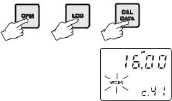
Note The password cannot be viewed when SETUP is pressed without entering the original password first. The default password is set at “0000”. In the event that the user forgets the password, this can be reset to “0000” by pressing and holding CFM and then pressing LCD and CAL DATA at the same time when the pH controller is in normal operating mode (idle or control with measurement displaying).
Note When a wrong setup value is con-
firmed, the pH controller does not skip to the next setup item but remains in the current item displaying a flashing “WRONG” indicator until the parameter value is changed by the user (the
same is also true for the setup code selection). In some circumstances, the user cannot succeed in setting a parameter to a desired value if the related parameters are not changed beforehand; e.g. to set a pH high setpoint to 10.00 the high alarm must be set to a value greater than pH 10.00 first.
Note Forcodenumbers40,41,42,theoutputisrelatedtopHormVunits dependingonthemodel(pHprocessmetersormVprocessmeters). Items41and42arenotavailable inpH5025YZ andmV6025YZ.
16

CONTROL MODE
The control mode is the normal operational mode for these meters. During control mode pH 502 and mV 602 fulfill the following main tasks:
•convert information from pH/ORP and temperature inputs to digital values;
•control relays and generate the analog outputs as determined by the setup configuration, display alarm condition;
•RS485 management (if the feature is included).
In addition, pH 502 and mV 602 can log working data through RS485 connection. This data includes:
•pH, mV and oC measured values;
•last calibration data;
•setup configuration (also from PC).
The status of the meter is shown by the LED’s on the right
|
STATUS |
|
LEDs |
|
Control |
Alarm |
Alarm LED (green) |
RelayLED(yellow) |
Red LED |
|
|
|
|
|
OFF |
---- |
ON |
OFF |
ON |
|
|
|
|
|
ON |
OFF |
ON |
ON or OFF |
OFF |
|
|
|
|
|
ON |
ON |
OFF |
ON or OFF |
Blinking |
|
|
|
|
|
Meter exits control mode by pressing SETUP or CAL and confirming the password. Note that this command generates a temporary exit. To deactivate the con-
trol mode definitively, set CONTROL ENABLE to “0” (item # 02).
RELAY MODES
Once enabled, the relays 1 and 2 can be used in four different modes):
1)ON/OFF, high setpoint (acid dosage) (not for pH5025YZ and mV6025YZ);
2)ON/OFF, low setpoint (base dosage) (not for pH5025YZ and mV6025YZ);
3)PID, low setpoint (base dosage, if available);
4)PID, high setpoint (acid dosage, if available).
17

An upper boundary is imposed for acid/base dosage time when relays are energized continuously, i.e. when relay works in ON/OFF mode or in PID mode but in the latter case only if the relay is always ON. This parameter can be set through setup procedure. When the maximum boundary is reached, an alarm is generated; device stays in alarm condition until relay is de-energized.
ON/OFF CONTROL MODE
Either for mode 1 or 2 (base or acid dosage) the user has to define the following values through setup:
• relay setpoint (pH/mV value);
• relay hysteresis (pH/mV value). 


 Connect your device to the COM and
NO (Normally Open) or NC (Normally 


 Closed) terminals.


Note The NC contact is available with electromechanical relays only.
The ON relay state occurs when relay is energized (NO and COM connected, NC and COM disconnected).
The OFF relay state occurs when relay is de-energized (NO and COM disconnected, NC and COM connected).
The following graphs show relay states along with pH measured value (similar graph can be derived for mV control).
As shown below, a high setpoint relay is activated when the measured pH exceeds the setpoint and is deactivated when it is below the setpoint value minus hysteresis.
ON |
|
|
OFF |
|
|
Setpoint – |
Setpoint |
14 |
Hysteresis |
|
|
Such a behavior is suitable to control an acid dosing pump. A low setpoint relay as can be seen from the following graphs is energized when the pH value is below the setpoint and is de-energized when the pH value is above the sum of setpoint and the hysteresis. The low setpoint relay may be used to control an alkaline dosing pump.
18

ON |
|
|
OFF |
|
|
Setpoint |
Setpoint + |
14 |
|
Hysteresis |
|
P.I.D. CONTROL MODE
PID control is designed to eliminate the cycling associated with ON/OFF control in a rapid and steady way by means of the combination of the proportional, integral and derivative control methods.
With the proportional function, the duration of the activated control is proportional to the error value (Duty Cycle Control Mode): as the measurement approaches setpoint, the ON period diminishes.
The following graph describes the pH process controller behavior. Similar graph may apply to the mV controller.
|
|
|
|
|
|
|
|
|
|
|
|
|
|
|
|
|
|
|
t0 |
t0+Tc |
|
t0+2Tc |
t0+3Tc |
|||
During proportional control the process controller calculates the relay activation time at certain moments t0, t0+Tc, t0+2Tc etc. The ON interval (the shaded areas) is then dependent to the error amplitude.
With the integral function (reset), the controller will reach a more stable output around the setpoint providing a more accurate control than with the ON/OFF or proportional action only.
The derivative function (rate action) compensates for rapid changes in the system reducing undershoot and overshoot of the pH value.
During PID control, the ON interval is dependent not only to the error amplitude but even to the previous measurements.
Definitely PID control provides more accurate and stable control than ON/OFF controllers and it is best suitable in system with a fast response, quickly reacting to changes due to addition of acid or base solution.
19
Anexample ofhow theresponse overshootcan beimproved with a proper rate action setting is depicted in the following graphic.
pH
RATE ACTION COMPENSATES FOR RAPID CHANGES |
t |
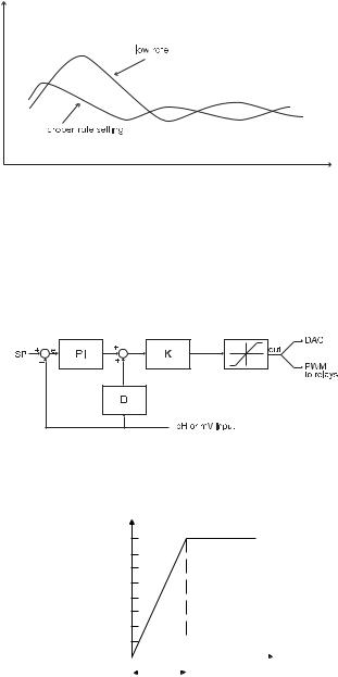
PID TRANSFER FUNCTION
The transfer function of a PID control is as follows:
Kp + Ki/s + s Kd = Kp(1 + 1/(s Ti) +s Td) with Ti = Kp/Ki, Td = Kd/Kp,
where the first term represents the proportional action, the second is the integrative action and the third is the derivative action.
Proportional action can be set by means of the Proportional Band (PB). Proportional Band is expressed in percentage of the input range and is related to Kp according to the following:
Kp = 100/PB.
100%
Controller output
|
|
|
|
0 |
|
|
Error |
|
|||
|
|
|
|
Proportional Band
20
In pH502 and mV602 the proportional action is set directly as “Deviation” in pH and mV units respectively. Relation between Deviation (D) and PB is:
D = Range * PB/100
Each setpoint has a selectable proportional band: PB1 for setpoint1 and PB2 for setpoint2. Two further parameters must be provided for both setpoints:
Ti = Kp/Ki, reset time, measured in minutes Td = Kd/Kp, rate time, measured in minutes.
Ti1 and Td1 will be the reset time and rate time for setpoint1, while Ti2 and Td2 will be the reset time and the rate time for setpoint2.
TUNING A PID CONTROLLER
The proportional, integrative, derivative terms must be tuned, i.e. adjusted to a particular process. Since usually the process variables are not completely known, a “trial and error” tuning procedure must be applied to get the best possible control for the particular process. The target is to achieve a fast response time and a small overshoot.
Many tuning procedures are available and can be applied to pH502 and mV602. A simple and profitable procedure is reported in this manual and can be used in almost all applications.
The user can vary five different parameters, i.e. the setpoint (S1 or S2), the deviation (D1 or D2), the reset time, the rate time and the proportional control mode period Tc (from 1 to 30 minutes for models with electromechanical relays and from 5 seconds to 30 minutes for models with SSR).
Note User can disable the derivative and/or integrative action (for P or PI controllers) by setting Td = 0 and/or Ti = MAX (Ti) respectively through the setup procedure.
SIMPLE TUNING PROCEDURE
The following procedure uses a graphical technique of analyzing a process response curve to a step input.
Note Connecting an external device (chart recorder or PC) to the controller, the procedure is easier and doesn’t need the use of hand plotting the process variable (pH or mV).
21
1.Starting from a solution with a pH or mV value different from the dosed liquid (at least a 3 pH or 150mV difference) turn on the dosing device at its maximum capacity without the controller in the loop (open loop process). Note the starting time.
2.After some delay the pH or mV starts to vary. After more delay, the pH or mV will reach a maximum rate of change (slope). Note the time that this maximum slope occurs and the pH or mV value at which it occurs. Note the maximum slope in pH or mV per minute. Turn the system power off.
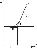
3.On the chart draw a tangent to the maximum slope point until intersection with the horizontal line corresponding to the initial pHormVvalue.ReadthesystemtimedelayTxonthetimeaxis.
4.Thedeviation,TiandTdcanbecalculatedfromthefollowing:
•Deviation = Tx * max. slope (pH or mV)
•Ti = Tx / 0.4 (minutes)
•Td = Tx * 0.4 (minutes).
5.Set the above parameters and restart the system with the controller in the loop. If the response has too much overshoot or is oscillating, then the system can be fine-tuned slightly increasing or decreasing the PID parameters one at a time.
Example:
the chart recording in the figure  aside was obtained continuously dosing an alkaline solution to a weak acid solution in a tank. The initial settings will be:
Max. slope = 3 pH/5 mins = 0.6 pH/min
Time delay = Tx = approx. 7 mins Deviation = Tx * 0.6 = 4.2 pH Ti = Tx / 0.4 = 17.5 mins
Td = Tx * 0.4 = 2.8 mins
22
 Loading...