


HI 2216
Instruction Manual
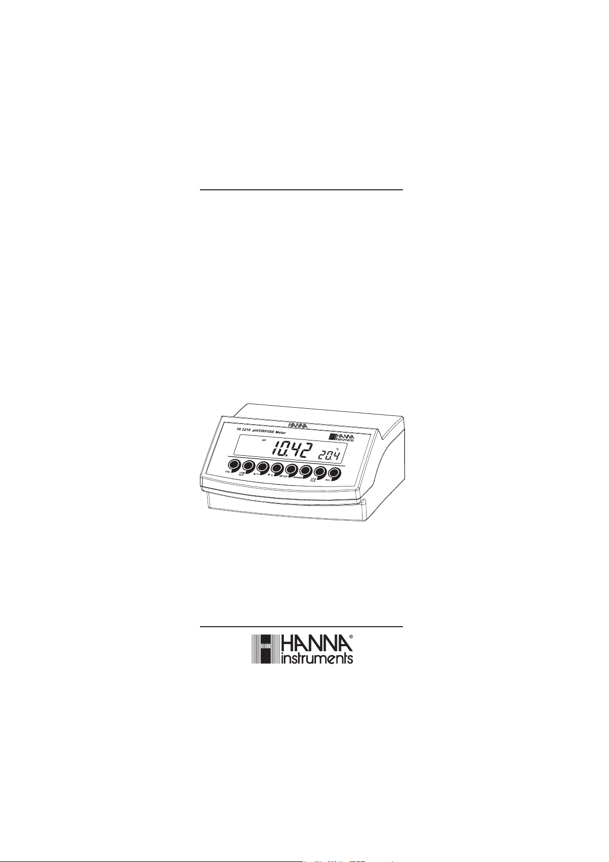
HI 2216
pH/mV/ISE/°C
Bench Meter
with Custom Buffers
and Interval Logging
www.hannainst.com
1

Dear Customer,
Thank you for choosing a Hanna Instruments product.
Please read this instruction manual carefully before using this instrument.
This manual will provide you with the necessary information for correct
use of this instrument, as well as a precise idea of its versatility.
If you need additional technical information, do not hesitate to e-mail us
at tech@hannainst.com or view our worldwide contact list at
www.hannainst.com.
WARRANTYWARRANTY
WARRANTY
WARRANTYWARRANTY
HI 2216 is guaranteed for two years against defects in workmanship and
materials when used for their intended purpose and maintained according
to instructions. Electrodes and probes are guaranteed for six months. This
warranty is limited to repair or replacement free of charge.
Damage due to accidents, misuse, tampering or lack of prescribed
maintenance is not covered.
If service is required, contact the dealer from whom you purchased the
instrument. If under warranty, report the model number, date of
purchase, serial number and the nature of the problem. If the repair is
not covered by the warranty, you will be notified of the charges incurred.
If the instrument is to be returned to Hanna Instruments, first obtain a
Returned Goods Authorization number from the Technical Service
department and then send it with shipping costs prepaid. When shipping
any instrument, make sure it is properly packed for complete protection.
TABLE OF CONTENTSTABLE OF CONTENTS
TABLE OF CONTENTS
TABLE OF CONTENTSTABLE OF CONTENTS
WARRANTY ............................................................................................. 2
PRELIMINARY EXAMINATION ...................................................................... 3
GENERAL DESCRIPTION ............................................................................ 3
FUNCTIONAL DESCRIPTION ........................................................................ 4
SPECIFICATIONS ....................................................................................... 5
OPERATIONAL GUIDE ................................................................................ 6
pH CALIBRATION ...................................................................................... 9
pH BUFFER TEMPERATURE DEPENDENCE ................................................. 14
ISE CALIBRATION ................................................................................... 15
RELATIVE mV CALIBRATION .................................................................... 18
GOOD LABORATORY PRACTICE (GLP) ........................................................ 18
LOGGING FUNCTION ............................................................................... 23
SETUP .................................................................................................. 28
TEMPERATURE CALIBRATION (for technical personnel only) .......................... 33
mV CALIBRATION (for technical personnel only) .......................................... 34
PC INTERFACE ....................................................................................... 35
ELECTRODE CONDITIONING & MAINTENANCE ............................................. 40
TROUBLESHOOTING GUIDE ..................................................................... 43
TEMPERATURE CORRELATION FOR pH SENSITIVE GLASS ............................. 44
ACCESSORIES ........................................................................................ 45
2

PRELIMINARY EXAMINATIONPRELIMINARY EXAMINATION
PRELIMINARY EXAMINATION
PRELIMINARY EXAMINATIONPRELIMINARY EXAMINATION
Remove the instrument from the packing material and examine it carefully
to make sure that no damage has occurred during shipping. If there is any
damage, notify your Dealer or the nearest Hanna Customer Service Center.
Each instrument is supplied with:
• HI 1131B Glass-body Combination pH Electrode with 1 m (3.3')
Cable
• HI 7662 Temperature Probe
• HI 76404N Electrode Holder
• pH 4.01 & 7.01 Buffer Solutions (20 mL each)
• HI 7071 Electrolyte Solution
• HI 700661 Cleaning Solution
• 12VDC Power Adapter
• Instruction Manual
Note: Save all packing material until you are sure that the instrument
functions correctly. All defective items must be returned in the
original packing with the supplied accessories.
GENERAL DESCRIPTIONGENERAL DESCRIPTION
GENERAL DESCRIPTION
GENERAL DESCRIPTIONGENERAL DESCRIPTION
The HI 2216 is state of the art, heavy-duty pH, mV, ISE meter designed
to provide laboratory results and accuracy under harsh industrial
conditions.
HI 2216 can also measure Oxidation Reduction Potential (ORP) in mV
range.
Relative mV feature is also provided.
pH measurements are compensated for temperature effect manually or
automatically with the HI 7662 temperature probe.
Up to a five-point pH calibration can be performed using seven standard
buffers. In addition, two custom buffers can be used during calibration.
Up to a two-point ISE calibration can be performed using five standard
solutions.
The GLP feature provides data consistency.
A calibration due alarm can be set to alert the user that too much time
elapsed since the last pH calibration.
Data can be stored in meter’s memory for later retrieval.
An USB connection ensures communication with a PC.
The meter’s memory can hold 200 manually logged points and 500 lot
logging points.
3
FUNCTIONAL DESCRIPTIONFUNCTIONAL DESCRIPTION
FUNCTIONAL DESCRIPTION
FUNCTIONAL DESCRIPTIONFUNCTIONAL DESCRIPTION
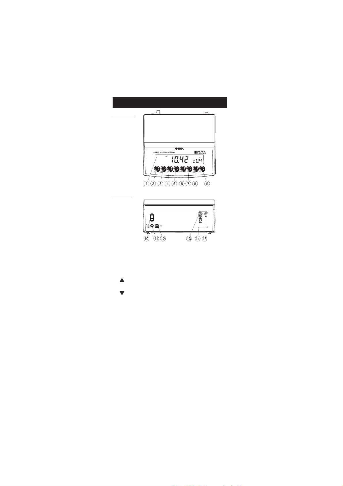
Front Panel
Rear Panel
1) Liquid Crystal Display (LCD).
2) CAL key, to enter and exit calibration mode.
3) CFM/GLP key, to confirm calibration, different values or to display
Good Laboratory Practice information.
4) ºC key, to manually increase temperature value or other
parameters.
5) ºC key, to manually decrease temperature value or other
parameters.
6) SETUP key, to enter/exit SETUP mode.
7) RANGE key, to select measurement range, switch to focused data in
SETUP or toggle between buffer value and temperature during
calibration.
8) LOG/CLR key, to store a value into memory, to clear pH calibration,
or to delete log records.
9) RCL key, memory recall.
10) ON/OFF switch.
11) Power supply socket.
12) USB connector.
13) BNC electrode connector.
14) Temperature probe socket.
15) Electrode reference socket.
4
EGNAR
Hp0.61ot0.2–
Hp00.61ot00.2–
Hp000.61ot000.2–
)PRO(Vm9.999±
)PRO(Vm0002±
mpp09991ot100.0
)F°0.842ot0.4-(Cº0.021ot0.02–
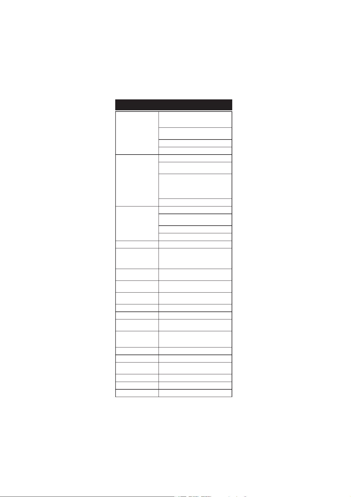
NOITULOSER
Hp100.0,Hp10.0,Hp1.0
)PRO&ESI()Vm9.999±(Vm1.0
)PRO&ESI()Vm0002±(Vm1
)mpp999.1ot(100.0
)mpp99.91ot(10.0
)mpp9.991ot(1.0
)mpp9991ot(1
)mpp09991ot(01
Cº1.0
YCARUCCA
F°86/C°02@
Hp200.0±,Hp10.0±,Hp1.0±
)Vm9.999±(Vm2.0±
)Vm0002±(Vm1±
SF%5.0±
)rorreeborpgnidulcxe(Cº2.0±
egnartesffoVmleR Vm0002±
noitarbilaCHp
,noitarbilactniop5otpu,citamotuA
elbaliavasreffubdradnats7
,)54.21,10.01,81.9,10.7,68.6,10.4,86.1(
sreffubmotsuc2dna
noitarbilaCESI
sreffub5,stniop2ro1,citamotuA
)mpp0001,001,01,1,1.0(elbaliava
erutarepmeT
noitasnepmoc
ro)eborp2667IHhtiw(citamotuA
Cº0.021ot0.02–morflaunam
edortcelEHp
,B1311IH ,noitcnujelgnis,ydob-ssalg
)dedulcni(rotcennocCNB,elballifer
eborperutarepmeT )dedulcni(2667IH
ecnadepmitupnI 01
21
smho
erutaefgoL
sdrocer002
dnamednogol
erutaeflavretnIgoL
,)bAtS(gniggolytilibatS
ces03,01,5
nim081,021,06,03,51,01,5,2,1
noitacinummocCP BSUdetalosi-otpO
ylppusrewoP )dedulcni(retpadaCDV21
tnemnorivnE
)Fº221–23(Cº05–0
gnisnednoc-nonHR%59.xam
snoisnemiD )”3.4x7.8x2.9(mm901x222x532
thgieW )bl9.2(gK3.1
ytnarraW sraey2
SPECIFICATIONSSPECIFICATIONS
SPECIFICATIONS
SPECIFICATIONSSPECIFICATIONS
5
OPERATIONAL GUIDEOPERATIONAL GUIDE
OPERATIONAL GUIDE
OPERATIONAL GUIDEOPERATIONAL GUIDE
POWER CONNECTION
Plug the 12 VDC adapter into the power supply socket.
Notes: • This instrument uses non volatile memory to retain the pH,
mV, temperature calibrations and all other settings, even
when unplugged.
• Make sure a fuse protects the main line.
ELECTRODE AND PROBE CONNECTIONS
For pH or ORP measurements connect an electrode with internal reference
to the BNC connector on the back of the instrument.
For electrodes with a separate reference connect the electrode’s BNC to the
BNC connector and the reference electrode plug to the reference socket.
For temperature measurements and automatic temperature compensation
connect the temperature probe to the appropriate socket.
INSTRUMENT START-UP
• Turn the instrument on by pressing the ON/OFF switch located on
the rear panel.
• All LCD tags are displayed and a beep is sounded while the instruments
perform a self test.
• The instrument will display “LoAd” message and “ ” blinking until
initialization is complete.
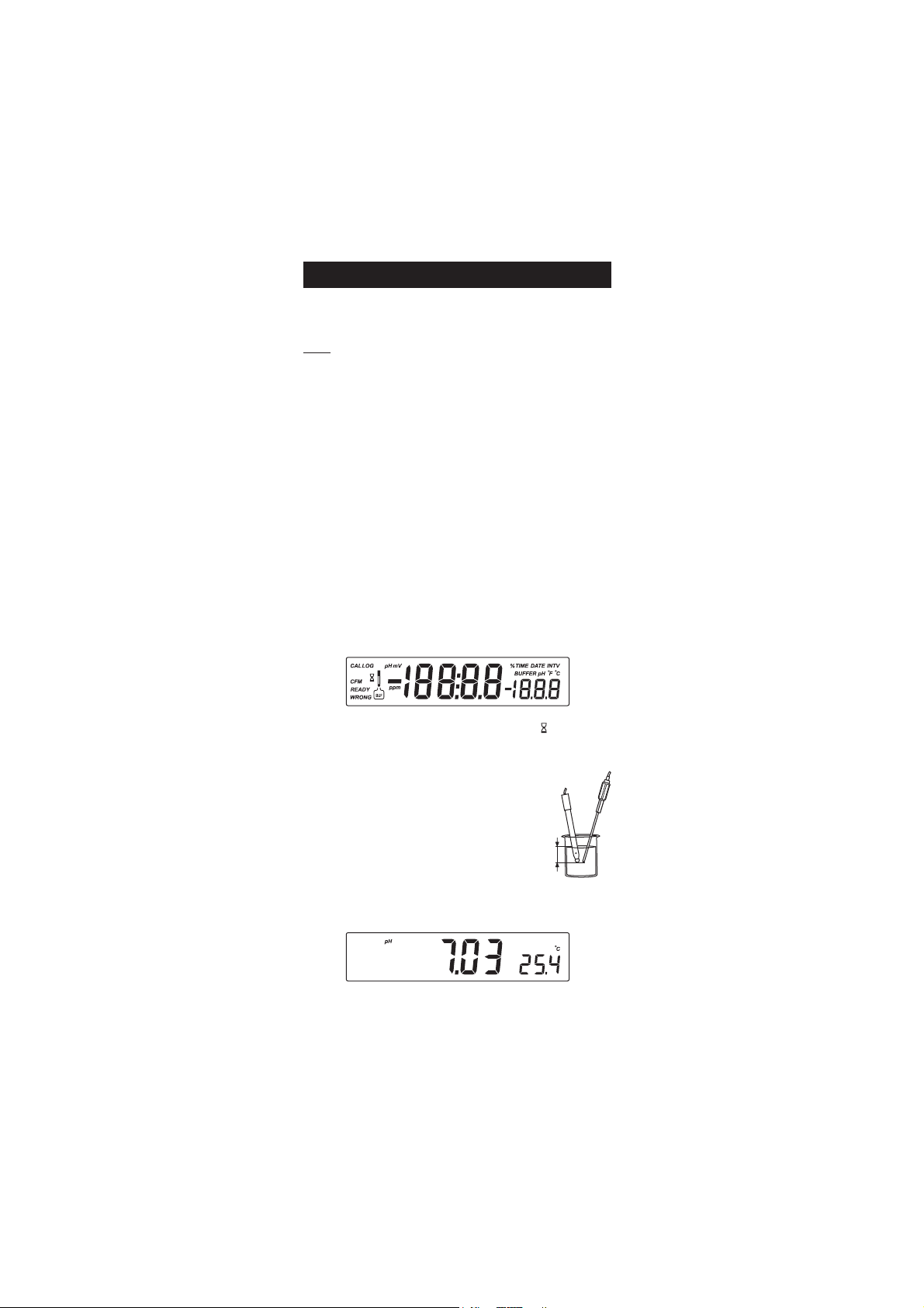
pH MEASUREMENTS
Make sure the instrument has been calibrated before
taking pH measurements.
• Submerse the electrode tip and the temperature
probe approximately 3 cm (1¼”) into the sample
to be tested and stir gently. Allow time for the
3 cm
(1¼")
electrode to stabilize.
• The pH is displayed on the primary LCD and the temperature on the
secondary LCD.
• If the reading is out of range, the closest full-scale value will be
displayed blinking on the primary LCD.
6
If measurements are taken successively in different samples, it is recommended
to rinse the electrode thoroughly with deionized water or tap water and
then with some of the next sample to prevent cross-contamination.
The pH reading is affected by temperature. In order to measure the pH
accurately, the temperature effect must be compensated for. To use the
Automatic Temperature Compensation feature, connect and submerse
the HI 7662 temperature probe into the sample as close as possible to
the electrode and wait for a few seconds.
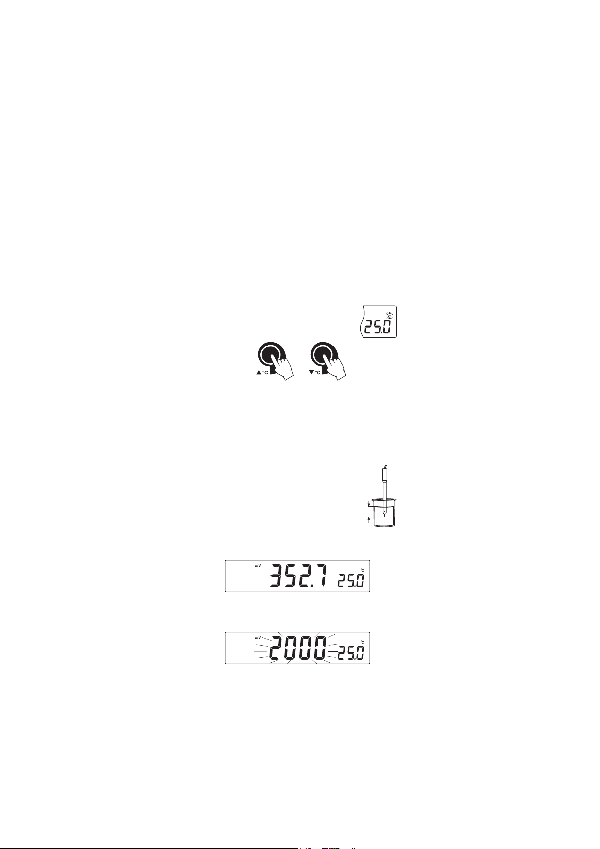
If the temperature of the sample is known, manual temperature
compensation can be used by disconnecting the temperature probe.
The display will show the last temperature reading with the “ºC” tag blinking.
The temperature can now be adjusted with the
ARROW keys (from -20.0 ºC to 120.0 ºC).
mV/ORP MEASUREMENTS
An optional ORP electrode must be used to perform ORP measurements
(see Accessories).
Oxidation-Reduction Potential (REDOX) measurements provide the
quantification of the oxidizing or reducing power of the tested sample.
The surface of the ORP electrode must be clean and smooth in order to
obtain an accurate measurement.
• Press RANGE to enter mV range.
• Submerse the tip of the ORP electrode 3 cm (1¼”)
into the sample to be tested and allow a few
seconds for the reading to stabilize.
3 cm
(1¼")
• The instrument displays the mV reading on the primary LCD and the
temperature on the secondary LCD.
• If the reading is out of range, the closest full-scale value will be
displayed blinking on the primary LCD.
7
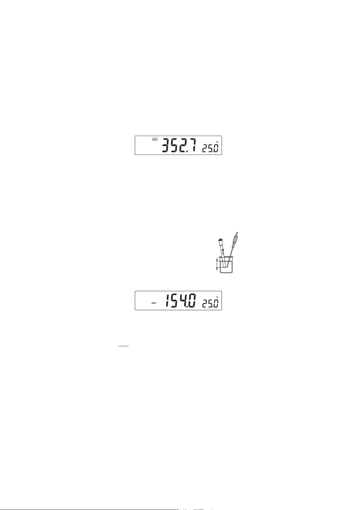
RELATIVE mV MEASUREMENTS
• Press RANGE until “rEL” message and “mV” tag are displayed for
one second. After one second the temperature will be displayed on
the secondary LCD and the “mv” tag will blink.
The reading displayed by the instrument is equal to the difference
between the current mV input value and relative mV offset established in
the relative mV calibration.
ISE MEASUREMENT
To perform ion concentration measurements, connect an optional ISE
electrode to the instrument input (BNC or BNC and REF if separate
reference electrode is used). Enter the ISE mode by pressing RANGE key
until the display changes to ppm. Select the corresponding ion charge in
the SETUP menu.
Submerse the ISE electrode (reference electrode) and
temperature probe (3 cm/1¼”) into the sample to
be tested and wait a few seconds for the reading to
stabilize.
The ppm reading will be displayed on the primary
3 cm
(1¼")
LCD and the current temperature value on the
secondary LCD.
In order to take accurate ISE measurements, make sure that the
appropriate ion charge was set in the SETUP menu and the instrument
was calibrated (see ISE CALIBRATION for details, page 15).
Notes: • When the reading is out of range, the display will flash the
closest full-scale value.
• The instrument will display “----” on the primary LCD if it is
not calibrated. Perform at least a one-point calibration if the
ion charge is -1, 1, -2, 2 or a two-point calibration for the
“undF” option selected in SETUP menu in order to take ISE
measurements.
8

TEMPERATURE MEASUREMENTS
Connect the HI 7662
appropriate socket and turn the instrument on.
Submerse the temperature
and allow the reading on the secondary LCD to stabilize.
Calibrate the instrument frequently, especially if high accuracy is
required.
The instrument should be recalibrated:
• Whenever the pH electrode is replaced.
• At least once a week.
• After testing aggressive chemicals.
• If “CAL” “INTV” tags are blinking during measurement.
Every time you calibrate the instrument use fresh buffers and perform an
electrode Cleaning Procedure (see page 42).
PREPARATION
Pour small quantities of the buffer solutions into clean beakers. If
possible, use plastic or glass beakers to minimize any EMC interferences.
For accurate calibration and to minimize cross-contamination, use two
beakers for each buffer solution. One for rinsing the electrode and one for
calibration.
If you are measuring in the acidic range, use pH 7.01 or 6.86 as first
buffer and pH 4.01 as second buffer. If you are measuring in the alkaline
range, use pH 7.01 or 6.86 as first buffer and pH 10.01 or 9.18 as
second buffer.
PROCEDURE
Calibration can be performed up to five-points.
For accurate measurements a three-point calibration is recommended.
The calibration buffer can be selected from the calibration buffer list that
includes the custom buffers and the memorized standard buffers:
• pH 1.68, 4.01, 6.86, 7.01, 9.18, 10.01 and 12.45.
temperature probe to the
probe
into the sample
pp
H CALIBRATIONH CALIBRATION
p
H CALIBRATION
pp
H CALIBRATIONH CALIBRATION
9
The custom buffers allow the user to calibrate in a buffer solution different
BUF
from a standard one. Up to two custom buffers can be set in SETUP menu
(see page 28). Each custom buffer value can be changed in a ±1.0 pH
window around the set value, during calibration, when it is selected; the
“BUFFER pH” tag will blink.
The instruments will automatically skip the buffer used during calibration
and the buffers which are in a ±0.2 pH window, around one of the
calibrated buffers.
All new calibrations will override existing stored calibration data in a
±0.2 pH window. The slopes adjacent to the new points will be reevaluated.
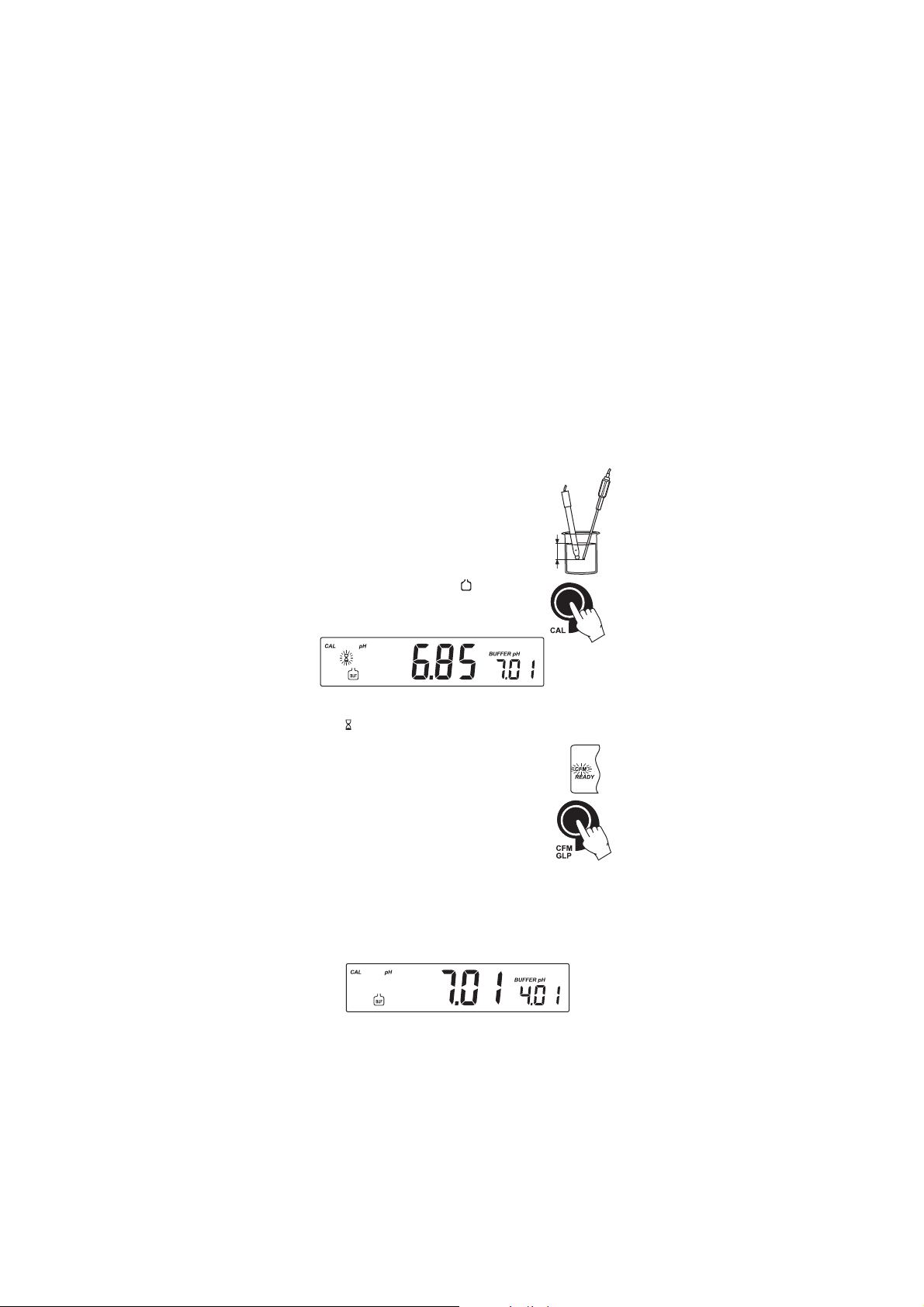
FIVE-POINT CALIBRATION
• Submerse the pH electrode and the temperature
probe approximately 3 cm (1¼”) into a buffer
solution and stir gently. The temperature probe
should be close to the pH electrode.
• Press CAL. The “CAL” and “
” tags will
3 cm
(1¼")
appear and the “7.01” buffer will be displayed
on the secondary LCD.
• If necessary, press the ARROW keys to select a different buffer value.
• The “ ” tag will blink on the LCD until the reading is stable.
• When the reading is stable and close to the selected
buffer, the “READY” tag will be displayed and the
“CFM” tag will blink.
• Press CFM to confirm calibration.
• The calibrated value will be displayed on the primary
LCD and the second expected buffer value on the
secondary LCD.
• After the first calibration point is confirmed, submerse the pH
electrode and the temperature probe approximately 3 cm (1¼”)
into the second buffer solution and stir gently. The temperature
probe should be close to the pH electrode.
• If necessary, press the ARROW keys to select a different buffer value.
10
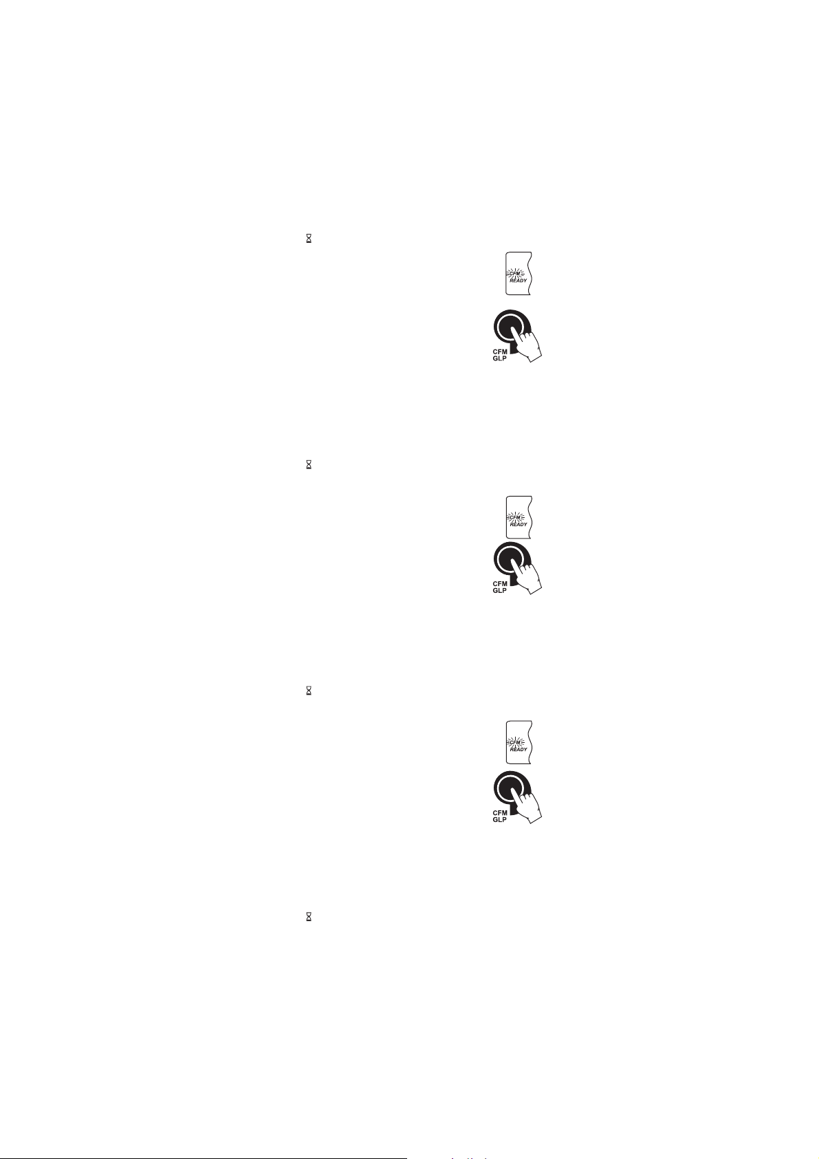
• The “ ” tag will blink on the LCD until the reading is stable.
• When the reading is stable and close to the selected
buffer, the “READY” tag will be displayed and the
“CFM” tag will blink.
• Press CFM to confirm calibration.
• The calibrated value is then displayed on the
primary LCD and the third expected buffer value on
the secondary LCD.
• After the second calibration point is confirmed, submerse the pH
electrode and the temperature probe approximately 3 cm (1¼”) into
the next buffer solution and stir gently. The temperature probe
should be close to the pH electrode.
• If necessary, press the ARROW keys to select a different buffer value.
• The “ ” tag will blink on the LCD until the reading is stable.
• When the reading is stable and close to the selected buffer, the
“READY” tag will be displayed and the “CFM” tag
will blink.
• Press CFM to confirm calibration.
• The calibrated value is then displayed on the
primary LCD and the fourth expected buffer value
on the secondary LCD.
• After the third calibration point is confirmed, submerse the pH
electrode and the temperature probe approximately 3 cm (1¼”) into
the next buffer solution and stir gently. The temperature probe should
be close to the pH electrode.
• If necessary, press the ARROW keys to select a different buffer value.
• The “ ” tag will blink on the LCD until the reading is stable.
• When the reading is stable and close to the selected buffer, the
“READY” tag will be displayed and the “CFM” tag
will blink.
• Press CFM to confirm calibration.
• The calibrated value is then displayed on the
primary LCD and the fifth expected buffer value on
the secondary LCD.
• After the fourth calibration point is confirmed, submerse the pH
electrode and the temperature probe approximately 3 cm (1¼”) into
the next buffer solution and stir gently. The temperature probe
should be close to the pH electrode.
• If necessary, press the ARROW keys to select a different buffer value.
• The “ ” tag will blink on the LCD until the reading is stable.
11

• When the reading is stable and close to the selected
buffer, the “READY” tag will be displayed and the
“CFM” tag will blink.
• Press CFM to confirm the fifth calibration point.
• The instrument stores the calibration value and
returns to normal measurement mode.
FOUR, THREE OR TWO-POINT CALIBRATION
• Proceed as described in “FIVE-POINT CALIBRATION” section.
• Press CAL after the fourth, third or second calibration point was
confirmed. The instrument will memorize the calibration data and
return to measurement mode.
ONE-POINT CALIBRATION
Two SETUP selectable options are available: “Pnt” and “OFFS”.
If the “Pnt” option is selected, the new calibration point overrides an
existing one. The adjacent slopes will be reevaluated.
If the “OFFS” option is selected, an electrode offset correction is performed.
The adjacent slopes will remain unchanged.
• Proceed as described in “FOUR, THREE or TWO-POINT CALIBRATION”
section.
• Press CAL after the first calibration point was confirmed. The
instrument will memorize the one-point calibration data and will
return to measurement mode.
Notes: • If the value measured by the instrument is not close to the
selected buffer, “WRONG” “ ” and “WRONG” “ ” tags
will blink alternately. Check if the correct buffer has been
used, or clean the electrode by following the Cleaning Procedure
(see page 42). If necessary, change the buffer or the electrode.
• When a custom buffer is displayed, the “BUFFER pH” tag
blinks. To change the custom buffer value in accordance with
the buffer temperature proceed as described in “WORKING
WITH CUSTOM BUFFERS” (see page 13).
• If the buffer temperature or the manual temperature
exceeds the temperature limits of the buffer, “WRONG” tag
and temperature reading will blink.
• If “WRONG”, “BUFFER pH” tags and “OLD” message are
displayed blinking on the secondary LCD line, an inconsistency
between new and previous (old) calibration is detected.
12
Clear calibration parameters and proceed with calibration
from the current calibration point. The instrument will keep
all confirmed values during current calibration.
• To clear calibration parameters for all uncalibrated buffers
starting with current buffer, press CLR. The calibration will
continue from the current point. If
this procedure is performed while calibrating in the first calibration point, the
instrument returns to measurement
mode.
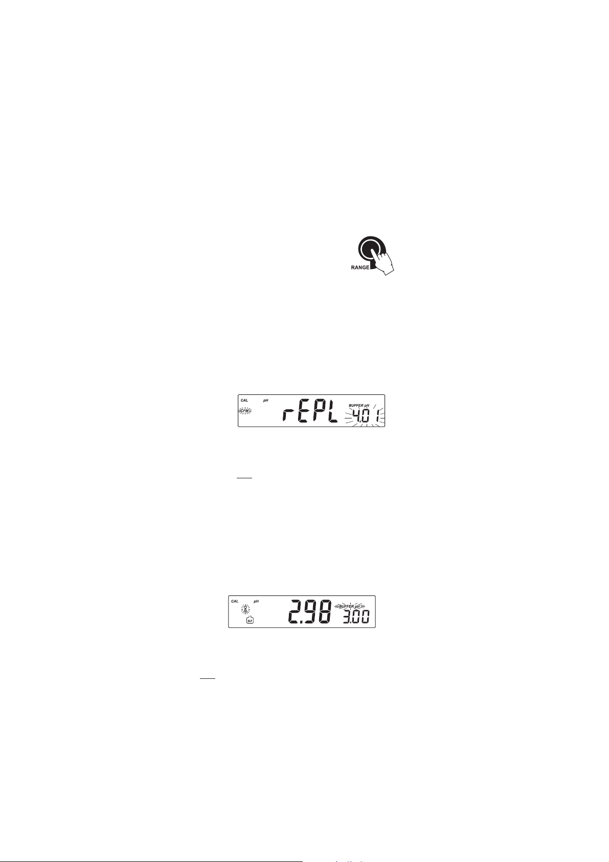
• Press RANGE to toggle between pH buffer, calibration
buffer number and temperature reading.
• Each time a buffer is confirmed, the new calibration data
replaces the old data for the coresponding buffer. If current
buffer has no previous data stored and the calibration is not
full (five buffers), the current buffer is added to the existing
calibration. If the existing calibration is full, the instrument
asks which buffer to replace.
Press the ARROW keys to select another buffer to be replaced.
Press CFM to confirm the buffer that will be replaced.
Press CAL to leave calibration without replacing.
Note: If the replaced buffer is outside the ±0.2 pH window,
around each of the calibrated buffers, it is possible to
select this buffer for next calibration during current
calibration.
WORKING WITH CUSTOM BUFFERS
If a custom buffer was set in SETUP menu, it can be selected during
calibration by pressing the ARROW keys. The “BUFFER pH” tag will
blink.
Press SETUP if you want to adjust the buffer value. The buffer value will
start blinking.
Use the ARROW keys to change the buffer value.
After 5 seconds, the buffer value is updated. Press SETUP if you want to
change it again.
Note: Custom buffer value can be adjusted in a ±1.00 pH window,
around the set value.
13
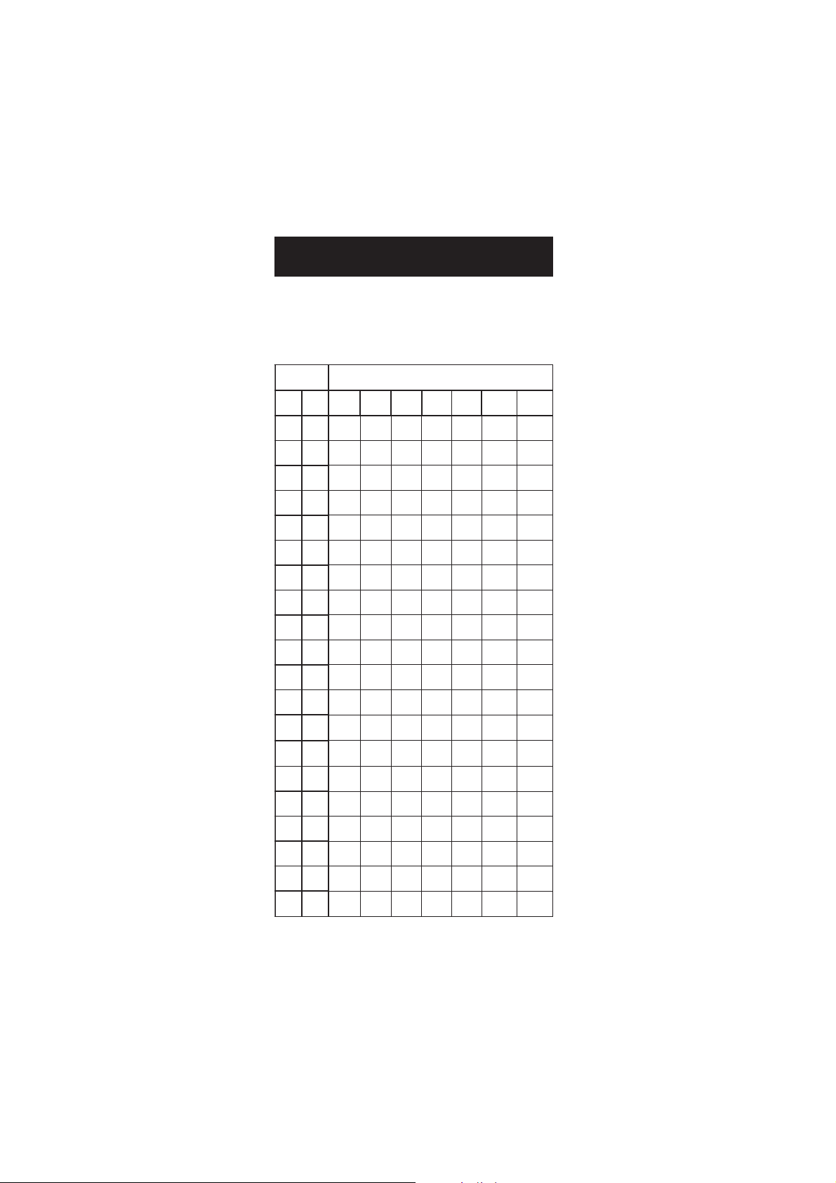
PMET SREFFUBHp
Cº Fº 86.1 10.4 68.6 10.7 81.9 10.01 54.21
0 23 76.1 10.4 89.6 31.7 64.9 23.01 83.31
5 14 76.1 00.4 59.6 01.7 93.9 42.01 81.31
01 05 76.1 00.4 29.6 70.7 33.9 81.01 99.21
51 95 76.1 00.4 09.6 50.7 72.9 21.01 08.21
02 86 86.1 00.4 88.6 30.7 22.9 60.01 26.21
52 77 86.1 10.4 68.6 10.7 81.9 10.01 54.21
03 68 86.1 20.4 58.6 00.7 41.9 69.9 92.21
53 59 96.1 30.4 48.6 99.6 11.9 29.9 31.21
04 401 96.1 40.4 48.6 89.6 70.9 88.9 89.11
54 311 07.1 50.4 38.6 89.6 40.9 58.9 38.11
05 221 17.1 60.4 38.6 89.6 10.9 28.9 07.11
55 131 27.1 80.4 48.6 89.6 99.8 97.9 75.11
06 041 27.1 90.4 48.6 89.6 79.8 77.9 44.11
56 941 37.1 11.4 48.6 99.6 59.8 67.9 23.11
07 851 47.1 21.4 58.6 99.6 39.8 57.9 12.11
57 761 67.1 41.4 68.6 00.7 19.8 47.9 01.11
08 671 77.1 61.4 78.6 10.7 98.8 47.9 00.11
58 581 87.1 71.4 78.6 20.7 78.8 47.9 19.01
09 491 97.1 91.4 88.6 30.7 58.8 57.9 28.01
59 302 18.1 02.4 98.6 40.7 38.8 67.9 37.01
pp
H BUFFER TEMPERATUREH BUFFER TEMPERATURE
p
H BUFFER TEMPERATURE
pp
H BUFFER TEMPERATUREH BUFFER TEMPERATURE
DEPENDENCEDEPENDENCE
DEPENDENCE
DEPENDENCEDEPENDENCE
The temperature has an effect on pH. The calibration buffer solutions are
affected by temperature changes to a lesser degree than normal solutions.
During calibration the instrument will automatically calibrate to the pH
value corresponding to the measured or set temperature.
During calibration the instrument will display the pH buffer value at 25 ºC.
14
1
BUF
II
SESE
CALIBRATION CALIBRATION
I
SE
CALIBRATION
II
SESE
CALIBRATION CALIBRATION
It is recommended to calibrate the instrument frequently, especially if
high accuracy is required.
The ppm range should be recalibrated:
• Whenever the ISE electrode is replaced.
• When the ion charge is changed in SETUP menu.
• At least once a day.
• After testing agressive chemicals.
• When calibration is expired - “CAL” “INTV” tags blink (if feature is
enabled).
Due to electrode conditioning time, the electrode must be kept submersed
a few seconds to stabilize.
PROCEDURE
Select the proper ion charge in SETUP menu (see SETUP for details, page 28).
Note: If “undF” option is selected in SETUP menu, calibration must be
performed at two points. Otherwise “----” message will be
displayed on the LCD.
Pour small quantities of the calibration solutions into clean beakers. If
possible, use plastic beakers to minimize any EMC interferences.
For accurate calibration and to minimize cross-contamination, use two
beakers for each calibration solution. One for rinsing the electrode and
one for calibration.
Note: ISA needs to be added to all calibration solutions. See sensor
manual.
The instrument offers a choice of six standard solutions: 0.1, 1, 10, 100,
1000, 10000 ppm and calibration up to two points. Standards should
bracket the working range.
Remove the protective cap from the ISE electrode.
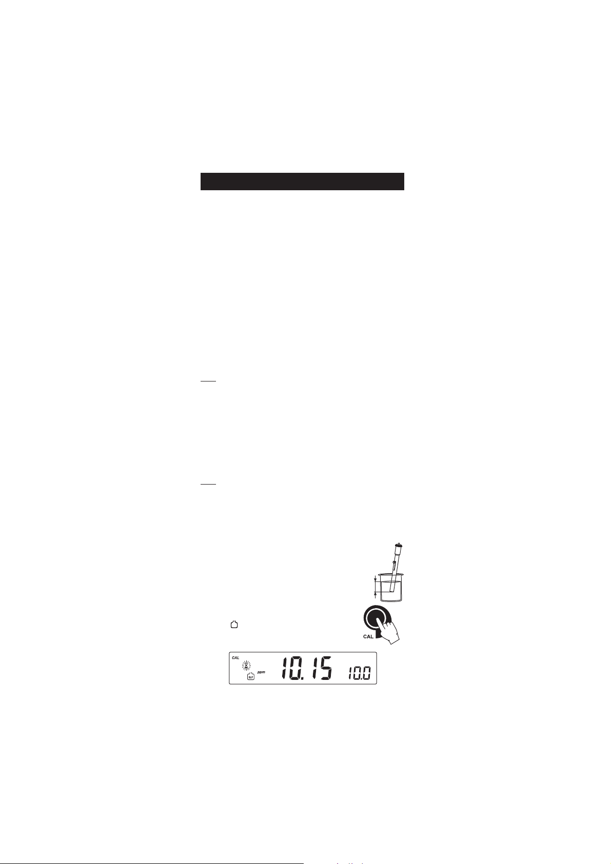
TWO-POINT CALIBRATION
• Submerse the ISE electrode approximately 3 cm
(1¼”) into the selected solution and stir gently.
3 cm
(1¼")
• Press CAL. The primary LCD will display the ppm
value using the current offset and slope. The “CAL”
and “
” tags will appear and “10.0” ppm
standard will be displayed on the secondary LCD.
15

• If necessary, press the ARROW keys to select a different standard
BUF
BUF
value.
• The “ ” tag will blink on the LCD until the reading
is stable.
• When the reading is stable and close to the selected
standard, the “READY” tag will be displayed and
the “CFM” tag will blink.
• Press CFM to confirm calibration.
• The calibrated value will be displayed on the primary LCD and the
second expected standard value on the secondary LCD.
Note: The instrument will automatically skip the standard used for the
first point.
• After the first calibration point is confirmed, submerse the ISE electrode
approximately 3 cm (1¼”) into the second calibration solution.
• If necessary, press the ARROW keys to select a different standard
value.
• The “ ” tag will blink on the LCD until the reading
is stable.
• When the reading is stable and close to the selected
standard, the “READY” tag will be displayed and
the “CFM” tag will blink.
• Press CFM to confirm calibration.
• The instrument stores the calibration value and returns to normal
measurement mode.
Notes: • If the mV value is out of the mV range (±2000), “WRONG”
“
” and “WRONG” “ ” tags will blink alternately. In this
case, check if the correct standard has been used.
• If the new slope is out of the slope window, “WRONG” “
”
and “WRONG” “ ” tags will blink alternately. In this case,
check if the correct standard has been used.
Slope window is between ±20 mV and ±120 mV if
ion charge is not specified (undF option in SETUP menu)
or between 50% and 120% of default slope for the
corresponding ion charge.
16
 Loading...