


Instruction Manual
HI 2550
Multiparameter
pH/ORP/°C
EC/TDS/NaCl
Bench Meter
www.hannainst.com
1

Dear Customer,
Thank you for choosing a Hanna Instruments product.
Please read this instruction manual carefully before using this instrument.
This manual will provide you with the necessary information for correct use of this instrument, as well as a precise idea of its versatility.
If you need additional technical information, do not hesitate to e-mail us at tech@hannainst.com.
WARRANTY
HI 2550 is guaranteed for two years against defects in workmanship and materials when used for their intended purpose and maintained according to instructions. Electrodes and probes are guaranteed for six months. This warranty is limited to repair or replacement free of charge.
Damage due to accidents, misuse, tampering or lack of prescribed maintenance is not covered.
If service is required, contact the dealer from whom you purchased the instrument. If under warranty, report the model number, date of purchase, serial number and the nature of the problem. If the repair is not covered by the warranty, you will be notified of the charges incurred. If the instrument is to be returned to Hanna Instruments, first obtain a Returned Goods Authorization number from the Technical Service department and then send it with shipping costs prepaid. When shipping any instrument, make sure it is properly packed for complete protection.
TABLE OF CONTENTS |
|
WARRANTY .................................................................................................... |
2 |
PRELIMINARY EXAMINATION ............................................................................ |
3 |
GENERAL DESCRIPTION .................................................................................... |
3 |
FUNCTIONAL DESCRIPTION .............................................................................. |
4 |
SPECIFICATIONS ............................................................................................. |
5 |
OPERATIONAL GUIDE ....................................................................................... |
7 |
AUTO-RANGING ............................................................................................. |
12 |
pH CALIBRATION ............................................................................................ |
13 |
pH BUFFER TEMPERATURE DEPENDENCE ......................................................... |
18 |
RELATIVE mV CALIBRATION .............................................................................. |
19 |
ECS/TDS CALIBRATION .................................................................................... |
19 |
CONDUCTIVITY VERSUS TEMPERATURE CHART ................................................... |
21 |
NaCl CALIBRATION ......................................................................................... |
22 |
GOOD LABORATORY PRACTICE (GLP) ................................................................. |
23 |
LOGGING FUNCTION ....................................................................................... |
28 |
SETUP .......................................................................................................... |
36 |
TEMPERATURE CALIBRATION (FOR TECHNICAL PERSONNEL ONLY) ....................... |
42 |
mV CALIBRATION (FOR TECHNICAL PERSONNEL ONLY) ....................................... |
44 |
PC INTERFACE ............................................................................................... |
45 |
ELECTRODE CONDITIONING & MAINTENANCE .................................................... |
51 |
TROUBLESHOOTING GUIDE .............................................................................. |
54 |
TEMPERATURE CORRELATION FOR pH SENSITIVE GLASS ..................................... |
55 |
ACCESSORIES ............................................................................................... |
56 |
2

PRELIMINARY EXAMINATION
Remove the instrument from the packing material and examine it carefully to make sure that no damage has occurred during shipping. If there is any damage, notify your Dealer or the nearest Hanna Customer Service Center.
Each instrument is supplied with:
•HI 1131B Glass-body Combination pH Electrode with 1 m (3.3') Cable
•HI 76310 Conductivity / TDS probe
•HI 7662 Temperature Probe
•HI 76404N Electrode Holder
•pH 4.01 & 7.01 Buffer Solutions (20 mL each)
•HI 7071 Electrolyte Solution
•12VDC Power Adapter
•Instruction Manual
Note: Save all packing material until you are sure that the instrument functions correctly. All defective items must be returned in the
original packing with the supplied accessories.
GENERAL DESCRIPTION
The HI 2550 is a microprocessor based pH, ORP, Conductivity (EC), TDS, NaCl, and Temperature Bench Meter. Relative mV feature is also provided.
pH measurements are compensated for temperature effect manually or automatically with the HI 7662 temperature probe.
Up to a five-point pH calibration can be performed using seven standard buffers and two custom buffers.
A calibration due alarm can be set to alert the user that too much time has elapsed since the last pH calibration.
Conductivity and TDS features auto-ranging, which automatically selects the scale with the highest resolution. Conductivity measurements are compensated for temperature manually or automatically with a temperature sensor located inside the probe. The temperature coefficient is user selectable. Temperature compensation can be disabled to measure actual conductivity.
The GLP feature provides data consistency.
Data can be stored in the meters memory for later retrieval. The meters memory can hold 200 manually logged points and 500 lot logging points.
An USB connection ensures communication with a PC.
3
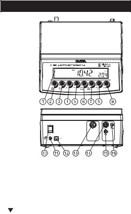
FUNCTIONAL DESCRIPTION
Front Panel
Rear Panel
1)Liquid Crystal Display (LCD).
2)CAL key, to enter and exit calibration mode.
RCL key (alternate function), to enter and exit memory recall.
3)CFM/GLP key, to confirm calibration selection, different setup values or to display Good Laboratory Practice information.
4) ºC key, to manually increase temperature value or other parameters. TC key (alternate function), to view temperature coefficient value.
5)ºC key, to manually decrease temperature value or other parameters.
ATC key (alternate function), to select EC temperature compensation mode.
6)SETUP key, to enter/exit SETUP mode.
LOCK key (alternate function), to freeze current EC range on the LCD.
7)RANGE key, to select measurement range (pH, mV, EC), switch to focused data in SETUP or toggle between buffer value and temperature during calibration.
MODE key (alternate function) to select mV or Rel mV on mV range or EC, TDS, NaCl on EC range.
8)LOG/CLR key, to store a value into memory, to clear pH calibration, or to select to delete log records or lots.
9)ALT key, to select alternate function.
10)ON/OFF switch.
11)Power supply socket.
12)USB connector.
13)EC electrode connector.
14)BNC electrode connector.
15)Temperature probe socket.
16)Electrode reference socket.
4

SPECIFICATIONS
|
–2.0 to 16.0 pH |
|
|
–2.00 to 16.00 pH |
|
|
–2.000 to 16.000 pH |
|
|
|
|
|
±999.9 mV (ISE & ORP) |
|
|
±2000 mV (ISE & ORP) |
|
|
|
|
|
0.00 to 29.99 μS/cm |
|
|
30.0 to 299.9 μS/cm |
|
|
300 to 2999 μS/cm |
|
|
3.00 to 29.99 mS/cm |
|
|
30.0 to 200.0 mS/cm |
|
RANGE |
up to 500.0 mS/cm uncompensated(*) |
|
|
conductivity |
|
|
|
|
|
0.00 to 14.99 ppm |
|
|
15.0 to 149.9 ppm |
|
|
150 to 1499 ppm |
|
|
1.50 to 14.99 g/l |
|
|
15.0 to 100.0 g/l |
|
|
up to 400.0 g/l uncompensated(*) TDS |
|
|
(with 0.80 factor) |
|
|
|
|
|
0.0 to 400.0% NaCl |
|
|
|
|
|
–20.0 to 120.0 ºC (pH, EC range) |
|
|
|
|
|
0.1 pH |
|
|
0.01 pH |
|
|
0.001 pH |
|
|
|
|
|
0.1 mV (±1000.0 mV) |
|
|
1 mV (±2000 mV) |
|
|
|
|
|
0.01 μS/cm |
|
|
0.1 μS/cm |
|
|
1 μS/cm |
|
RESOLUTION |
0.01 mS/cm |
|
0.1 mS/cm |
||
|
||
|
|
|
|
0.01 ppm |
|
|
0.1 ppm |
|
|
1 ppm |
|
|
0.01 g/l |
|
|
0.1 g/l |
|
|
|
|
|
0.1% NaCl |
|
|
|
|
|
0.1 ºC |
|
|
|
|
|
±0.01 pH |
|
|
±0.002 pH |
|
|
|
|
|
±0.2 mV (±999.9 mV) |
|
|
±1 mV (±2000 mV) |
|
|
|
|
ACCURACY |
±1 % reading (±0.05 μS/cm or 1 |
|
digit, whichever greater) |
||
@ 20°C / 68°F |
||
|
||
|
±1 % of reading (±0.03 ppm or 1 |
|
|
digit, whichever greater) |
|
|
|
|
|
±1% of reading |
|
|
|
|
|
±0.4 ºC (excluding probe error) |
|
|
|
(*) Uncompensated conductivity (or TDS) is the conductivity (or TDS) value without temperature compensation.
5
Rel mV offset range |
±2000 mV |
|
|
|
|
|
1, 2, 3, 4 or 5 point calibration, |
|
pH Calibration |
7 standard buffers available |
|
(1.68, 4.01, 6.86, 7.01, 9.18, 10.01, 12.45), |
||
|
||
|
and 2 custom buffers |
|
|
|
|
|
1 point slope calibration; |
|
|
6 buffers available: |
|
EC Calibration |
84.0, 1413 μS/cm |
|
5.00, 12.88, 80.0, 111.8 mS/cm |
||
|
||
|
1 point offset: |
|
|
0.00 μS/cm |
|
|
|
|
NaCl Calibration |
1 point with HI 7037L buffer (optional) |
|
|
|
|
|
Manual or Automatic from: |
|
Temperature |
–20.0 to 120.0 ºC (pH RANGE) |
|
–20.0 to 120.0 ºC (EC RANGE) |
||
compensation |
||
(can be disabled on conductivity range to |
||
|
||
|
measure actual conductivity |
|
|
|
|
Conductivity |
0.00 to 6.00 %/ºC |
|
(for EC and TDS only) |
||
temperature coefficient |
||
default value is 1.90 %/ºC |
||
|
||
|
|
|
TDS factor |
0.40 to 0.80 |
|
(default value is 0.50) |
||
|
||
|
|
|
pH Electrode |
HI 1131B |
|
|
|
|
EC Probe |
HI 76310 |
|
|
|
|
Temperature probe |
HI 7662 |
|
|
|
|
Input impedance |
1012 ohms |
|
(BNC input) |
||
|
||
|
|
|
Log on demand feature |
200 records |
|
|
|
|
|
500 records |
|
Log Interval feature |
Stability logging (”StAb”), |
|
5, 10, 30 sec |
||
|
||
|
1, 2, 5, 10, 15, 30, 60, 120, 180 min |
|
|
|
|
PC communication |
Optoisolated USB |
|
|
|
|
Power supply |
12 VDC adapter |
|
|
|
|
Dimensions |
235 x 222 x 109 mm (9.2 x 8.7 x 4.3”) |
|
|
|
|
Weight |
1.3 Kg (2.9 lb); |
|
kit with holder 2.1 Kg (4.6 lb) |
||
|
||
|
|
|
Environment |
0 – 50 ºC (32 – 122 ºF) |
|
max. 95% RH non-condensing |
||
|
||
|
|
|
Warranty |
2 years |
|
|
|
6
OPERATIONAL GUIDE
POWER CONNECTION
Plug the 12 VDC adapter into the power supply socket.
Notes: • This instrument uses non volatile memory to retain the calibration parameters and all other settings, even when unplugged.
• Make sure a fuse protects the main line.
ELECTRODE AND PROBE CONNECTIONS
For pH or ORP measurements connect an electrode with internal reference to the BNC connector on the back of the instrument.
For electrodes with a separate reference connect the electrode’s BNC to the BNC connector and the reference electrode plug to the reference socket.
For temperature measurements and automatic temperature compensation connect the temperature probe to the appropriate socket.
For EC/TDS measurements connect the probe to the 7-pin connector. Make sure the probe sleeve is properly inserted.
INSTRUMENT START-UP
•Turn the instrument on by pressing the ON/OFF switch located on the rear panel.
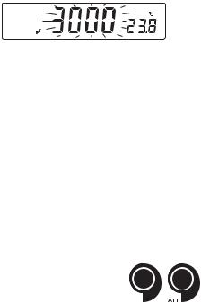
•All LCD tags are displayed and a beep is sounded while the instruments perform a self test.
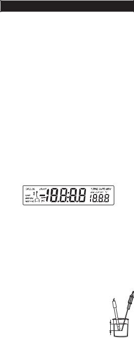
•The instrument will display “LoAd” message and “ ” blinking until initialization is complete.
Notes: • The instrument starts in the same range and mode as it was at power off.
•The ALT&MODE keys change the measuring modes:
-mV or Rel mV
-EC or TDS or NaCl
•The RANGE key toggles between measurement ranges:
-pH, mV or Rel mV, EC or TDS or NaCl.
pH MEASUREMENTS
Make sure the instrument has been calibrated before taking pH measurements.
•Submerse the electrode tip and the temperature probe approximately 3 cm (1¼”) into the sample to be tested and stir gently. Allow time for the electrode to stabilize.
3 cm (1¼")
7
•The pH is displayed on the primary LCD and the temperature on the secondary LCD.
pH
•If the reading is out of range, the closest full-scale value will be displayed blinking on the primary LCD.
pH
If measurements are taken successively in different samples, it is recommended to rinse the electrode thoroughly with deionized water or tap water and then with some of the next sample to prevent cross-contamination.
The pH reading is affected by temperature. In order to measure the pH accurately, the temperature effect must be compensated for. To use the Automatic Temperature Compensation feature, connect and submerse the HI 7662 temperature probe into the sample as close as possible to the electrode and wait for a few seconds.
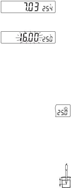
If the temperature of the sample is known, manual temperature compensation can be used by disconnecting the temperature probe.
The display will show the last temperature reading with
the “ºC” tag blinking.
The temperature can now be adjusted with the ARROW keys (from –20.0 ºC to 120.0 ºC).
mV/ORP MEASUREMENTS
An optional ORP electrode must be used to perform ORP measurements (see Accessories).
Oxidation-Reduction Potential (REDOX) measurements provide the quantification of the oxidizing or reducing power of the tested sample.
The surface of the ORP electrode must be clean and smooth in order to obtain an accurate measurement.
•Press RANGE to enter mV range.
•Submerse the tip of the ORP electrode (3 cm/1¼”) into the sample to be tested and allow a few seconds for the reading to stabilize.
3 cm (1¼")
8
•The instrument displays the mV reading on the primary LCD and the temperature on the secondary LCD line.
mV
•If the reading is out of range, the closest full-scale value will be displayed blinking on the primary LCD.
mV
RELATIVE mV MEASUREMENTS
•Press the ALT&MODE keys simultaneously while in mV range. The “rEL” and “mV” tags are displayed for about one second. After one second the temperature will be displayed on the secondary LCD and the “mV” tag will blink.
mV
The reading displayed by the instrument is equal to the difference between the current mV input value and the relative mV offset established in the relative mV calibration.
CONDUCTIVITY MEASUREMENTS
Connect the conductivity probe to the instrument.
•Press the RANGE key to enter conductivity measurement range (EC).
•Submerse the probe into the solution to be tested. The
sleeve holes must be completely submersed. Tap the probe repeatedly to remove any air bubbles that may be trapped inside the sleeve.
•The conductivity value will be displayed on the primary LCD and the temperature on the secondary LCD.
•If the reading is out of range, the full-scale value (200.0 for MTC/ATC mode or 500.0 for actual conductivity) will be displayed blinking.
9
•If LOCK key was pressed and the reading goes out of range, the full-scale value of the frozen range will be displayed blinking.
The conductivity reading is affected by temperature.
Three options for temperature compensation are available in conductivity measurement mode.
Automatic (ATC): The conductivity probe has a built-in temperature sensor; the temperature value is used to automatically compensate the EC/TDS reading.
Manual (MTC): The temperature value, shown on the secondary LCD, can be manually set with the ARROW keys. The “ºC” tag blinks when this option is active. This value will be used to compensate the EC/TDS reading.
No Compensation (notc): The temperature value is displayed, but not taken into account. When this option is selected the “ºC” tag will blink with slower frequency. The reading displayed on the primary LCD is the uncompensated EC or TDS value.
To select the desired option, press the ALT&ATC keys until the option is displayed
on the LCD. 
 Notes: • The default compensation mode is ATC.
•If no temperature probe is detected, ATC mode can not be selected and the instrument displays “----” on the secondary LCD.
If temperature compensation is selected, measurements are compensated using the temperature coefficient (default value 1.90 %/ºC). To change the temperature coefficient, enter the setup mode and select “tc” (see SETUP for details, page 36). The current temperature coefficient can be quickly viewed by pressing the ALT&TC keys. The value is briefly displayed on the secondary LCD.
•If the temperature reading exceeds the limits of the meter (–20.0 ºC to 120.0 ºC), the “ºC” tag will blink and the closest full scale value will be displayed.
10
TDS MEASUREMENTS
Press the ALT&MODE keys while in EC range. The instrument will switch to TDS measuring range. The TDS reading will be displayed on the primary LCD and the temperature reading on the secondary LCD.
•If the reading is out of range, the full-scale value (100.0 for MTC/ATC mode or 400.0 for uncompensated TDS) will be displayed blinking.
•If LOCK was pressed and the reading goes out of range, the full-scale value of the frozen range will be displayed blinking.
NaCl MEASUREMENTS
Press the ALT&MODE keys while in EC range until NaCl is displayed on the LCD. The instrument will display the NaCl reading on the primary LCD and the temperature reading on the secondary LCD line.
•If the reading is out of range, the full-scale value (400.0%) will be displayed blinking.
TEMPERATURE MEASUREMENTS
In pH and ORP mode, connect the HI 7662 temperature probe to the appropriate socket.
Submerse the temperature probe into the sample and allow the reading on the secondary LCD to stabilize.
In EC/TDS/NaCl range, the HI 76310 probe has a built-in temperature sensor.
11

AUTO-RANGING
The EC and TDS scales are auto-ranging. The meter automatically sets the scale with the highest possible resolution.
By pressing ALT&LOCK, the auto-ranging feature is disabled and the current range is frozen on the LCD. The “Auto” “Off” (auto-ranging disabled) tags will be displayed on the LCD for a few seconds. To restore the auto-ranging option, press ALT&LOCK again. The “Auto” “On” (auto-ranging enabled) tags will be displayed on the LCD for a few seconds.
Note: Auto-ranging is automatically restored if the range is changed, if the setup or calibration modes are entered and if the meter is turned off and back on again.
12

pH CALIBRATION
Calibrate the instrument frequently, especially if high accuracy is required. The instrument should be recalibrated:
•Whenever the pH electrode is replaced.
•At least once a day.
•After testing aggressive chemicals.
•If “CAL” “INTV” tags are blinking during measurement.
Every time you calibrate the instrument use fresh buffers and perform an electrode Cleaning Procedure (see page 53).
PREPARATION
Pour small quantities of the buffer solutions into clean beakers. If possible, use plastic or glass beakers to minimize any EMC interferences.
For accurate calibration and to minimize cross-contamination, use two beakers for each buffer solution. One for rinsing the electrode and one for calibration.
If you are measuring in the acidic range, use pH 7.01 or 6.86 as first buffer and pH 4.01 as second buffer. If you are measuring in the alkaline range, use pH 7.01 or 6.86 as first buffer and pH 10.01 or 9.18 as second buffer.
PROCEDURE
Calibration can be performed at up to five-points.
For accurate measurements, a three-point calibration is recommended.
The calibration buffer can be selected from the calibration buffer list that includes the custom buffers and the memorized standard buffers:
• pH 1.68, 4.01, 6.86, 7.01, 9.18, 10.01 and 12.45
The custom buffers allow the user to calibrate in a buffer solution different from a standard one. Up to two custom buffers can be set in SETUP menu (see page 36). Each custom buffer value can be changed in a ±1.0 pH window around the set value, during calibration, when it is selected; the “BUFFER pH” tag will blink.
The instruments will automatically skip the buffer used during calibration and the buffers which are in a ±0.2 pH window, around one of the calibrated buffers.
All new calibrations will override existing stored calibration data in a ±0.2 pH window. The slopes adjacent to the new points will be reevaluated.
13
FIVE-POINT CALIBRATION
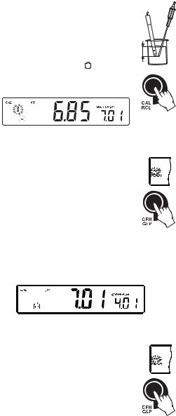
•Submerse the pH electrode and the temperature probe approximately 3 cm (1¼”) into a buffer solution and stir gently. The temperature probe should be close to the pH electrode.
•Press CAL. The “CAL” and “ BUF ” tags will appear and the “7.01” buffer will be displayed on the secondary LCD.
3 cm (1¼")
•If necessary, press the ARROW keys to select a different buffer value.
•The “ ” tag will blink on the LCD until the reading is stable.
•When the reading is stable and close to the selected
buffer, the “READY” tag will be displayed and the “CFM” tag will blink.
•Press CFM to confirm calibration.
•The calibrated value is then displayed on the primary
LCD and the second expected buffer value on the secondary LCD.
•After the first calibration point is confirmed, submerse the pH electrode and the temperature probe approximately 3 cm (1¼”) into the second buffer solution and stir gently. The temperature probe should be close to the pH electrode.
•If necessary, press the ARROW keys to select a different buffer value.
•The “ ” tag will blink on the LCD until the reading is stable.
•When the reading is stable and close to the selected
buffer, the “READY” tag will be displayed and the “CFM” tag will blink.
•Press CFM to confirm calibration.
•The calibrated value is then displayed on the primary
LCD and the third expected buffer value on the secondary LCD.
•After the second calibration point is confirmed, submerse the pH electrode and the temperature probe approximately 3 cm (1¼”) into the third buffer solution and stir gently. The temperature probe should be close to the pH electrode.
14

•If necessary, press the ARROW keys to select a different buffer value.
•The “ ” tag will blink on the LCD until the reading is
stable.
•When the reading is stable and close to the selected buffer, the “READY” tag will be displayed and the
“CFM” tag will blink.
• Press CFM to confirm calibration.
•The calibrated value is then displayed on the primary LCD and the fourth expected buffer value on the secondary LCD.
•After the third calibration point is confirmed, submerse the pH electrode and the temperature probe approximately 3 cm (1¼”) into the fourth buffer solution and stir gently. The temperature probe should be close to the pH electrode.
•If necessary, press the ARROW keys to select a different buffer value.
•The “ ” tag will blink on the LCD until the reading is
stable.
•When the reading is stable and close to the selected buffer, the “READY” tag will be displayed and the
“CFM” tag will blink.
• Press CFM to confirm calibration.
•The calibrated value is then displayed on the primary LCD and the fifth expected buffer value on the secondary LCD.
•After the fourth calibration point is confirmed, submerse the pH electrode and the temperature probe approximately 3 cm (1¼”) into the fifth buffer solution and stir gently. The temperature probe should be close to the pH electrode.
•If necessary, press the ARROW keys to select a different buffer value.
•The “ ” tag will blink on the LCD until the reading is
stable.
•When the reading is stable and close to the selected buffer, the “READY” tag will be displayed and the
“CFM” tag will blink.
• Press CFM to confirm the fifth calibration point.
•The instrument stores the calibration value and returns to normal measurement mode.
FOUR, THREE OR TWO-POINT CALIBRATION
•Proceed as described in “FIVE-POINT CALIBRATION” section.
•Press CAL after the fourth, third or second calibration point was confirmed. The instruments will memorize the calibration data and return to measurement mode.
15

ONE-POINT CALIBRATION
Two SETUP selectable options are available: “Pnt” and “OFFS”.
If the “Pnt” option is selected, the new calibration point overrides an existing one. The adjacent slopes will be reevaluated.
If the “OFFS” option is selected, an electrode offset correction is performed. The adjacent slopes will remain unchanged.
•Proceed as described in “FOUR, THREE or TWO-POINT CALIBRATION” section.
•Press CAL after the first calibration point was confirmed. The instruments will memorize the one-point calibration data and return to measurement mode.
Notes: • If the value measured by the instrument is not close to the
selected buffer, “WRONG” “ ” and “WRONG” “

 ” tags will blink alternately. Check if the correct buffer has been used, or clean the electrode by following the Cleaning Procedure (see page 53). If necessary, change the buffer or the electrode.
•When a custom buffer is displayed, the “BUFFER pH” tag blinks. To change the custom buffer value in accordance with the buffer temperature proceed as described in “WORKING WITH CUSTOM BUFFERS” (see page 17).
•If the buffer temperature or the manual temperature exceeds the temperature limits of the buffer, “WRONG” tag and temperature reading will blink.
•If “WRONG”, “BUFFER pH” tags and “OLD” message are displayed blinking on the secondary LCD line, an inconsistency between new and previous (old) calibration is detected. Clear calibration parameters and proceed with calibration from the current calibration point. The instrument will keep all confirmed values during current calibration.
•To clear calibration parameters for all uncalibrated buffers starting with current buffer, press CLR. The calibration will continue from the current point. If this procedure is performed while calibrating in the first calibration point, the instrument returns to measurement mode.
•Press RANGE to toggle between pH buffer,
calibration buffer number and temperature reading. 


16
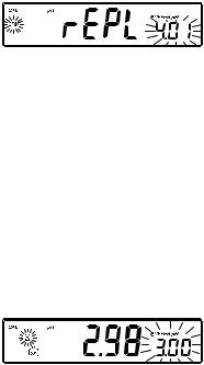
•Each time a buffer is confirmed, the new calibration data replaces the old calibration data for the corresponding buffer. If current buffer has no previous data stored and the calibration is not full (five buffers), the current buffer is added to the existing calibration. If the existing calibration is full, the instrument asks which buffer to replace.
Press the ARROW keys to select another buffer to be replaced.
Press CFM to confirm the buffer that will be replaced. Press CAL to leave calibration without replacing.
Note: If the replaced buffer is outside the ±0.2 pH window, around each of the calibrated buffers, it is possible to select this buffer for next calibration during current calibration.
WORKING WITH CUSTOM BUFFERS
If a custom buffer was set in SETUP menu, it can be selected during calibration by pressing the ARROW keys. The “BUFFER pH” tag will blink.
Press SETUP if you want to adjust the buffer value. The buffer value will
start blinking.
Use the ARROW keys to change the buffer value.
After 5 seconds, the buffer value is updated. Press SETUP if you want to change it again.
Note: Custom buffer value can be adjusted in a ±1.00 pH window, around the set value.
17

pH BUFFER TEMPERATURE DEPENDENCE
The temperature has an effect on pH. The calibration buffer solutions are affected by temperature changes to a lesser degree than normal solutions. During calibration the instrument will automatically calibrate to the pH value corresponding to the measured or set temperature.
TEMP |
|
|
pH BUFFERS |
|
|
|||
|
|
|
|
|
|
|
|
|
ºC |
ºF |
1.68 |
4.01 |
6.86 |
7.01 |
9.18 |
10.01 |
12.45 |
|
|
|
|
|
|
|
|
|
0 |
32 |
1.67 |
4.01 |
6.98 |
7.13 |
9.46 |
10.32 |
13.38 |
|
|
|
|
|
|
|
|
|
5 |
41 |
1.67 |
4.00 |
6.95 |
7.10 |
9.39 |
10.24 |
13.18 |
|
|
|
|
|
|
|
|
|
10 |
50 |
1.67 |
4.00 |
6.92 |
7.07 |
9.33 |
10.18 |
12.99 |
|
|
|
|
|
|
|
|
|
15 |
59 |
1.67 |
4.00 |
6.90 |
7.05 |
9.27 |
10.12 |
12.80 |
|
|
|
|
|
|
|
|
|
20 |
68 |
1.68 |
4.00 |
6.88 |
7.03 |
9.22 |
10.06 |
12.62 |
|
|
|
|
|
|
|
|
|
25 |
77 |
1.68 |
4.01 |
6.86 |
7.01 |
9.18 |
10.01 |
12.45 |
|
|
|
|
|
|
|
|
|
30 |
86 |
1.68 |
4.02 |
6.85 |
7.00 |
9.14 |
9.96 |
12.29 |
|
|
|
|
|
|
|
|
|
35 |
95 |
1.69 |
4.03 |
6.84 |
6.99 |
9.11 |
9.92 |
12.13 |
|
|
|
|
|
|
|
|
|
40 |
104 |
1.69 |
4.04 |
6.84 |
6.98 |
9.07 |
9.88 |
11.98 |
|
|
|
|
|
|
|
|
|
45 |
113 |
1.70 |
4.05 |
6.83 |
6.98 |
9.04 |
9.85 |
11.83 |
|
|
|
|
|
|
|
|
|
50 |
122 |
1.71 |
4.06 |
6.83 |
6.98 |
9.01 |
9.82 |
11.70 |
|
|
|
|
|
|
|
|
|
55 |
131 |
1.72 |
4.08 |
6.84 |
6.98 |
8.99 |
9.79 |
11.57 |
|
|
|
|
|
|
|
|
|
60 |
140 |
1.72 |
4.09 |
6.84 |
6.98 |
8.97 |
9.77 |
11.44 |
|
|
|
|
|
|
|
|
|
65 |
149 |
1.73 |
4.11 |
6.84 |
6.99 |
8.95 |
9.76 |
11.32 |
|
|
|
|
|
|
|
|
|
70 |
158 |
1.74 |
4.12 |
6.85 |
6.99 |
8.93 |
9.75 |
11.21 |
|
|
|
|
|
|
|
|
|
75 |
167 |
1.76 |
4.14 |
6.86 |
7.00 |
8.91 |
9.74 |
11.10 |
|
|
|
|
|
|
|
|
|
80 |
176 |
1.77 |
4.16 |
6.87 |
7.01 |
8.89 |
9.74 |
11.00 |
|
|
|
|
|
|
|
|
|
85 |
185 |
1.78 |
4.17 |
6.87 |
7.02 |
8.87 |
9.74 |
10.91 |
|
|
|
|
|
|
|
|
|
90 |
194 |
1.79 |
4.19 |
6.88 |
7.03 |
8.85 |
9.75 |
10.82 |
|
|
|
|
|
|
|
|
|
95 |
203 |
1.81 |
4.20 |
6.89 |
7.04 |
8.83 |
9.76 |
10.73 |
|
|
|
|
|
|
|
|
|
During calibration the instrument will display the pH buffer value at 25 ºC.
18
RELATIVE mV CALIBRATION
•Press CAL when the instrument is in RELATIVE mV measurement mode. The “mV” and “ ” tags will be displayed. Absolute mV is displayed on the primary LCD and “AbS” message is displayed on the secondary LCD.
•When the absolute reading is stable and in measurement range, the instrument asks for confirmation.
•If the reading is out of range, “WRONG” tag will be displayed.
•Press CFM to confirm the absolute value. The instrument will display 0.0 mV on the primary LCD and “rEL” message on the secondary LCD. In this moment the relative mV offset is equal to absolute mV reading.
•Use the ARROW keys if you want to change the displayed relative mV value.
•Press CFM to confirm the relative mV value. The instrument returns to measurement mode.
Note: The relative mV value can be changed only inside the relative mV offset window (± 2000 mV).
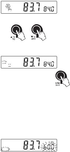
EC/TDS CALIBRATION
Selectable calibration points for conductivity are 0.00 μS for offset and 84.0 μS, 1413 μS, 5.00 mS, 12.88 mS, 80.0 mS, 111.8 mS for slope.
Rinse the probe with calibration solution or deionized
water. Submerse the probe into the solution. The sleeve holes must be completely submersed. Tap the probe repeatedly to remove any air bubbles that may be trapped
inside the sleeve.
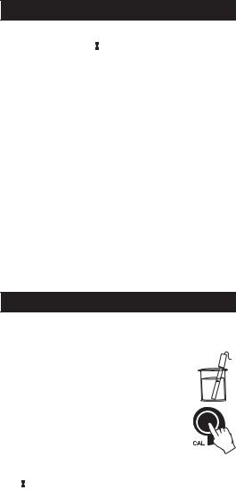
To enter EC calibration, select the EC range and press
CAL.
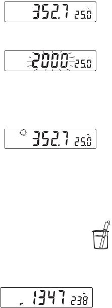
The “BUF” and “CAL” tags are displayed. The primary 

 LCD will display the EC reading. The secondary LCD will display the value. The “
 ” and “~” tags will blink.
Note: The TDS reading is automatically derived from the EC reading and no specific calibration for TDS is needed. Pressing CAL when TDS range is selected has no effect.
For zero calibration, just leave the dry probe in the air. This calibration is performed in order to correct the reading at 0.00 μS. The slope is evaluated when the calibration is performed at any other point.
19
CAL
BUF  S
S
Select the desired value with the ARROW keys, if necessary.
When the reading is stable, “READY” tag is displayed and “CFM” tag starts blinking on the LCD, asking for confirmation.
CAL
 CFM
CFM 
READY
BUF  S
S
Press CFM to confirm calibration.
The instrument stores the calibration value and returns to measurement mode.
Notes: • If the reading is too far from the expected value, the “WRONG” and “ ” tags will blink. Calibration can not be confirmed.
In this case check if the calibration solution has been used or clean the probe by following the Cleaning Procedure (see page 53).
•If the meter is in ATC mode and the buffer temperature is out of the 0.0 °C to 60.0 ºC interval, “WRONG” “ºC” tags and the temperature will blink.
CAL
WRONG
•For best results choose an EC buffer value close to the sample to be measured.
•In order to minimize any EMC interference, use plastic or glass beakers.
•It is possible to set the cell constant value directly, without following the calibration procedure. To set the cell constant, enter SETUP mode and select “CEL” (see SETUP for details, page 36).
20
 Loading...