


HI 3512
Instruction Manual
HI 3512
Two Channels
pH/ORP/ISE,
EC/TDS/NaCl/Resistivity,
Temperature
Bench Meter
www.hannainst.com
1

Dear Customer,
Thank you for choosing a Hanna Instruments product.
Please read this instruction manual carefully before using this instrument.
This manual will provide you with the necessary information for correct use
of this instrument, as well as a precise idea of their versatility.
If you need additional technical information, do not hesitate to e-mail us
at tech@hannainst.com or view our worldwide contact list at
www.hannainst.com.
WARRANTYWARRANTY
WARRANTY
WARRANTYWARRANTY
The HI 3512 is guaranteed for two years against defects in workmanship
and materials when used for their intended purpose and maintained
according to instructions. Electrodes and probes are guaranteed for six
months. This warranty is limited to repair or replacement free of charge.
Damage due to accidents, misuse, tampering or lack of prescribed
maintenance is not covered.
If service is required, contact the dealer from whom you purchased the
instrument. If under warranty, report the model number, date of purchase,
serial number and the nature of the problem. If the repair is not covered
by the warranty, you will be notified of the charges incurred. If the
instrument is to be returned to Hanna Instruments, first obtain a
Returned Goods Authorization number from the Technical Service
department and then send it with shipping costs prepaid. When shipping
any instrument, make sure it is properly packed for complete protection.
TABLE OF CONTENTSTABLE OF CONTENTS
TABLE OF CONTENTS
TABLE OF CONTENTSTABLE OF CONTENTS
WARRANTY ................................................................................................................................ 2
PRELIMINARY EXAMINATION ....................................................................................................... 3
GENERAL DESCRIPTION ............................................................................................................... 3
FUNCTIONAL DESCRIPTION ........................................................................................................ 5
SPECIFICATIONS ........................................................................................................................7
OPERATIONAL GUIDE .............................................................................................................. 10
AUTO-RANGING EC CHANNEL .................................................................................................... 15
TEMPERATURE COMPENSATION EC CHANNEL ............................................................................. 16
CONDUCTIVITY VERSUS TEMPERATURE CHART ............................................................................ 17
USER CALIBRATION ................................................................................................................. 18
pH CALIBRATION .................................................................................................................... 19
pH BUFFER TEMPERATURE DEPENDENCE ................................................................................... 27
RELATIVE mV CALIBRATION ..................................................................................................... 28
ISE CALIBRATION ................................................................................................................... 29
EC CALIBRATION .................................................................................................................... 33
GOOD LABORATORY PRACTICE (GLP) .......................................................................................... 37
SETUP ................................................................................................................................... 40
LOGGING ................................................................................................................................ 55
mV CALIBRATION (for technical personnel only) ......................................................................... 58
TEMPERATURE CALIBRATION (for technical personnel only) .......................................................... 59
PC INTERFACE ........................................................................................................................ 61
TEMPERATURE CORRELATION FOR pH SENSITIVE GLASS ............................................................... 71
ELECTRODE CONDITIONING & MAINTENANCE ............................................................................ 72
EC PROBE MAINTENANCE ........................................................................................................ 75
TROUBLESHOOTING GUIDE ..................................................................................................... 76
ACCESSORIES ......................................................................................................................... 77
2

PRELIMINARY EXAMINATIONPRELIMINARY EXAMINATION
PRELIMINARY EXAMINATION
PRELIMINARY EXAMINATIONPRELIMINARY EXAMINATION
Remove the instrument from the packing material and examine it carefully
to make sure that no damage has occurred during shipping. If there is any
damage, notify your Dealer or the nearest Hanna Customer Service Center.
Each instrument is supplied with:
• HI 1131B Glass body combination double-junction pH electrode
• HI 76310 Four Ring Conductivity Probe with built-in temperature
• HI 7662 -T stainless steel Temperature Probe with 1 m (3.3') Cable
• HI 70004 pH 4.01 Buffer Solution (20 mL sachet)
• HI 70007 pH 7.01 Buffer Solution (20 mL sachet)
• HI 700661 Cleaning solution (2x20 mL each)
• HI 7071S Electrolyte Solution
• HI 76404N Electrode Holder
• 12 Vdc Power Adaptor
• Instruction Manual
HI 3512 is supplied with 12 Vdc/230 Vac power adapter
HI 3512-01 is supplied with 12 Vdc/115 Vac power adapter
Note: Save all packing material until you are sure that the instrument
functions correctly. All defective items must be returned in the
original packing with the accessories supplied.
GENERAL DESCRIPTIONGENERAL DESCRIPTION
GENERAL DESCRIPTION
GENERAL DESCRIPTIONGENERAL DESCRIPTION
The HI 3512 instrument is state-of-the-art, professional bench meter
with graphical LCD, designed to provide laboratory results and accuracy.
Two input channels are available.
• Channel 1: pH/mV/ISE and temperature
• Channel 2: EC/TDS, NaCl/Resistivity and temperature
HI 3512 is provided with a series of new diagnostic features which add
an entirely new dimension to the measurement of pH and EC, by allowing
the user to dramatically improve the reliability of the measurement:
pH channel:
• 7 standard pH buffers (pH 1.68, 4.01, 6.86, 7.01, 9.18, 10.01
and 12.45) for calibration.
• pH calibration up to five calibration points (see instrument specifications).
• Custom calibration with up to two custom buffers.
• Messages on the graphic LCD for an easy and accurate calibration.
• Diagnostic features to alert the user when the electrode needs cleaning.
• User selectable “Out of cal. range“ warning.
• User selectable “Calibration Timeout“ to remind when a new
calibration is necessary.
3

• Extended temperature range on pH channel from –20 to 120 ºC
(–4 to 248 ºF), using HI 7662-T interchangeable temperature
probes.
EC channel:
• 7 memorized standards (0.00 µS/cm, 84.0 µS/cm, 1.413 mS/cm,
5.00 mS/cm, 12.88 mS/cm, 80.0 mS/cm and 111.8 mS/cm) for
calibration.
• EC calibration up to two calibration points.
• Messages on the graphic LCD for an easy and accurate calibration.
• Diagnostic features to alert the user when the electrode needs cleaning.
• User selectable “Out of cal. range” warning.
• User selectable “Calibration Timeout” to remind when a new
calibration is necessary.
• Extended temperature range on EC channel from –20 to 120 ºC
(–4 to 248 ºF), using temperature sensor inside EC probe.
• Temperature compensation selection
• Temperature reference selection 15 °C, 20 °C or 25 °C.
• Temperature coefficient set
• Lock and user setup Fixed range selection
Other features include:
• Log on demand up to 400 samples
• Log interval with log on stability feature up to 600 records
• Auto Hold feature, to freeze first stable reading on the LCD
• GLP feature, to view last calibration data for pH, Rel mV, ISE, EC or
NaCl.
• PC interface
This instrument can also measure with ORP electrodes (pH channel
input), thanks to their capability to measure mV with a resolution up to
0.1 mV and with ISE electrodes on ppm scale (pH channel input). The
electrode type and unit selection capability and the ISE calibration in up
to five calibration standard solutions make this instrument very useful
for a large range of concentration solutions measurements.
Relative mV feature is also available.
This instrument can also measure in Resistivity, TDS and Salinity on EC
channel.
4
FUNCTIONAL DESCRIPTIONFUNCTIONAL DESCRIPTION
FUNCTIONAL DESCRIPTION
FUNCTIONAL DESCRIPTIONFUNCTIONAL DESCRIPTION
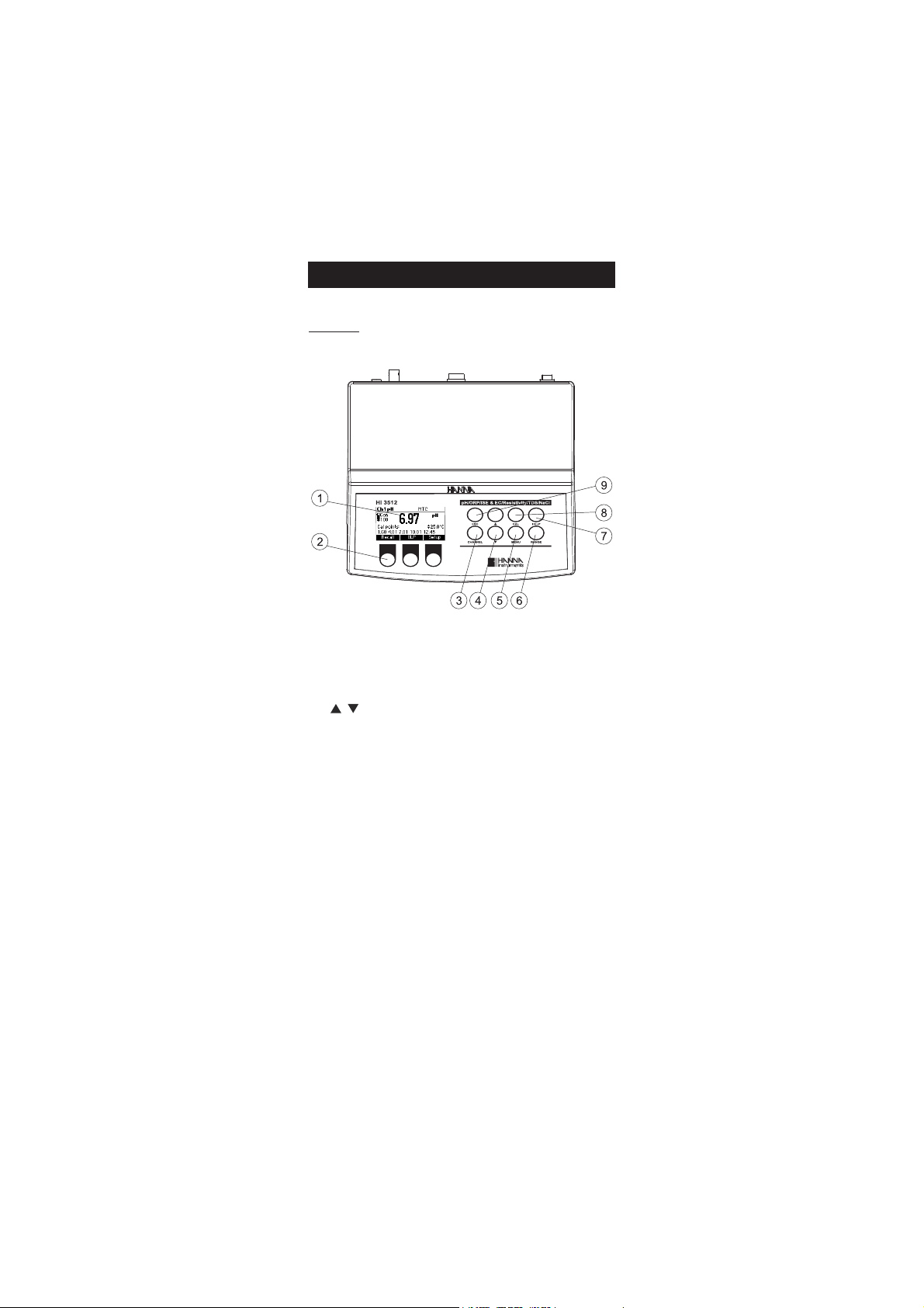
Front view
1) Liquid Crystal Display (LCD)
2) Function keys
3) CHANNEL keys to toggle between channels (Ch1 - pH, Ch2 - EC)
4) / keys to manually increase/decrease the parameters or to scroll
between the parameter list
5) MENU key, to change the function key at the bottom of the display
6) RANGE key, to switch between pH, mV and ISE range (Ch1); EC, Resitivity,
TDS and Salinity range (Ch2)
7) HELP key to enter/exit contextual help
8) CAL key, to enter calibration mode
9) ESC to escape the current mode, exit calibration, setup, help, etc.
5
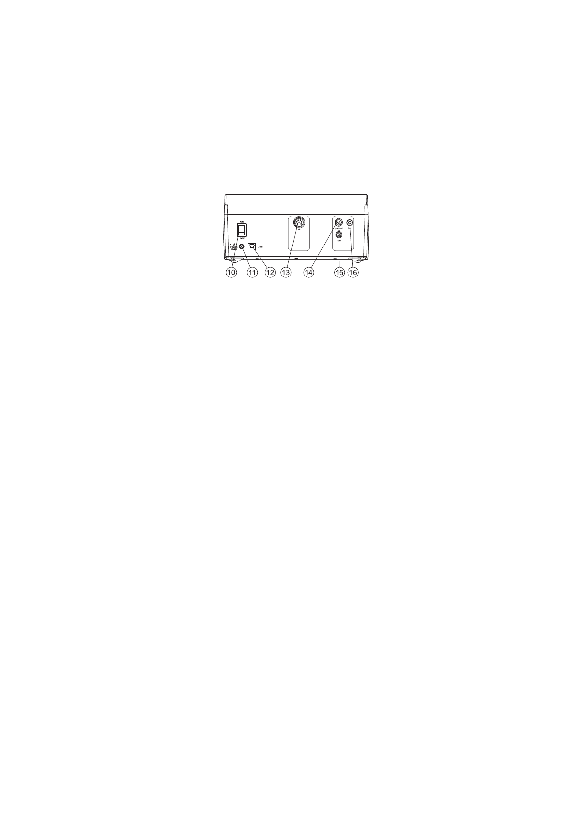
Rear view
10) ON/OFF switch.
11) Power adaptor socket.
12) USB connector.
13) DIN connector for EC probe.
14) BNC electrode connector for pH/ORP, ISE electrode.
15) Temperature socket for pH/ORP, ISE channel.
16) Reference electrode connector for pH/ORP, ISE channel.
6
egnaR
Hp0.02ot0.2–
Hp00.02ot00.2–
Hp000.02ot000.2–
Vm0.0002±
.cnoc01E99.9ot7-E00.1
)Fº0.842ot0.4(Cº0.021ot0.02–
1lennahC
noituloseR
00 Hp1.0
0 Hp10.0
Hp100.0
Vm1.0
.cnoc01,1,1.0,10.0stigid3
)Fº1.0(Cº1.0
ycaruccA
Fº86/Cº02@
Hp10.0±
Hp200.0±
Vm2.0±
)snoitnelavonom(gnidaerfo%5.0±
)snoitnelavid(gnidaerfo%1±
)Fº4.0±(Cº2.0±
)rorreeborpgnidulcxe(
egnartesffoVmleR Vm0002±
noitarbilaCHp
,noitarbilactniop-evifotpU
elbaliavasreffubdradnats7
,)54.21,10.01,81.9,10.7,68.6,10.4,86.1(
sreffubmotsuc2dna
noitarbilaCepolS %011ot08morF
erutarepmeTHp
noitasnepmoC
morfcitamotuArolaunaM
)Fº0.842ot0.4–(Cº0.021ot0.02–
edortcelEHp B1311IH )dedulcni(
eborperutarepmeT T-2667IH )dedulcni(
noitarbilaCESI
.stniopnoitarbilactniop-evifotpU
elbaliavasnoitulosdradnats6
)mpp00001,0001,001,01,1,1.0(
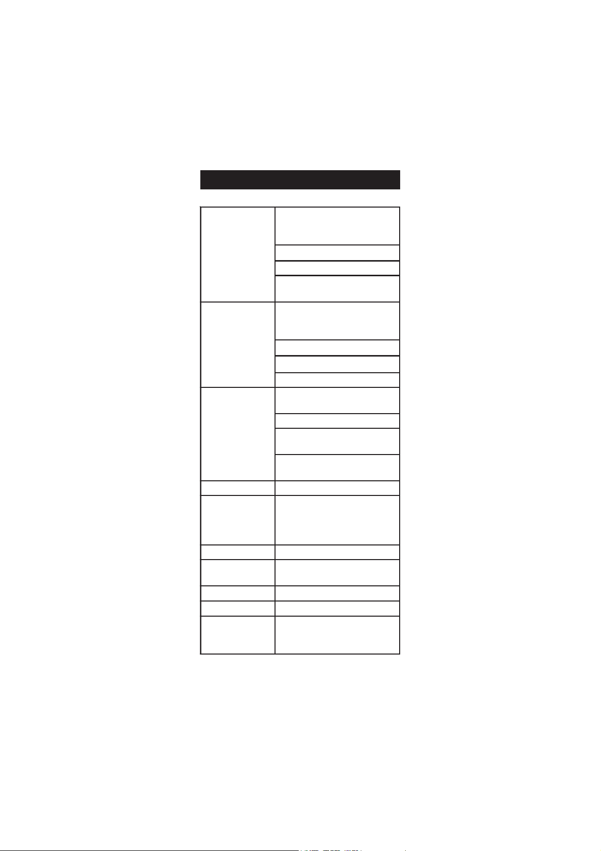
SPECIFICATIONSSPECIFICATIONS
SPECIFICATIONS
SPECIFICATIONSSPECIFICATIONS
7

CE
egnaR
00 mc/Sm004ot0
)mc/Sm0001otpuseulavswohs(
mc/Sm0001ytivitcudnoclautcA
mc/Sµ999.9ot100.0
mc/Sµ99.99ot00.01
mc/Sµ9.999ot0.001
mc/Sm999.9ot000.1
mc/Sm99.99ot00.01
. ot0.001 0 mc/Sm9.999
mc/Sm0001
)gnignarotua(
noituloseR
mc/Sµ100.0
0 mc/Sµ10.0
00 mc/Sµ1.0
mc/Sm100.0
0 mc/Sm10.0
00 mc/Sm1.0
.000 mc/Sm1
ycaruccA
gnidaerfo%1±
)retaergrevehcihwtigid1romc/Sµ10.0±(
rorreeborpgnidulcxe
ytivitsiseR
egnaR
0 ot0.1 1 smho9.99
. ot001 .1 smho999
ot00.1
1 smhoK99.9
ot0.01
1 smhoK9.99
. ot001 .1 smhoK999
ot00.1
1 smhoM99.9
smhoM0.001ot0.01
)gnignarotua(
noituloseR
0 mho1.0
.00 mho1
smhoK10.0
0 smhoK1.0
0.0 smhoK1
0 smhoM10.0
0 smhoM1.0
ycaruccA
gnidaerfo%1±
)retaergrevehcihwtigid1rosmho01±(
rorreeborpgnidulcxe
SDT
egnaR
mpp999.9ot000.0
mpp99.99ot00.01
mpp9.999ot0.001
L/g999.9ot000.1
L/g99.99ot00.01
L/g0.004ot0.001
)gnignarotua(
noituloseR
mpp1.0,mpp10.0,mpp100.0
L/g1.0,L/g10.0,L/g100.0
ycaruccA
gnidaerfo%1±
)retaergrevehcihwtigid1rompp50.0±(
rorreeborpgnidulcxe
8

ytinilaS
egnaR %0.004ot0.0:lCaN%
noituloseR %1.0
ycaruccA rorreeborpgnidulcxegnidaerfo%1±
erutarepmeT
2lennahC
egnaR C°0.021ot0.02-
noituloseR C°1.0
ycaruccA )rorreeborpgnidulcxe(C°2.0±
noitarbilaCCE
sdradnatsdeziromem7htiwstniop2otpucitamotuA
,mc/Sm00.5,mc/Sm314.1,mc/Sµ0.48,mc/Sµ00.0(
)mc/Sm8.111,mc/Sm0.08,mc/Sm88.21
putestnatsnoclleC 000.01ot010.0
noitarbilaClCaN
ylnotniop1.xaM
htiw( 3707IH ;)dradnats
eborpCE 01367IH
ecruoserutarepmeT
;eborpehtedisnirosnesmorfcitamotuA
yrtnelaunaM
erutarepmeTCE
noitasnepmoC
CTA,CTM,CToN
ecnerefeR
erutarepmeT
C°52,02,51
erutarepmeT
tneicifeoC
C°/%00.01ot00.0
rotcaFSDT 00.1ot04.0
dnamednoGOL selpmas004
gniggoltoL
ces03,01,5
dnEotuA,nim081,021,06,03,51,01,5,2,1
)selpmas006xam(
ecnadepmitupnI 01
21
smho
ylppusrewoP rotpadArewoPcdV21
ecafretniCP detalosi-otpo BSU
snoisnemiD )”33.4x41.8x2.9(mm011x702x532
)ylnoretem(thgieW )bl1.4(gK8.1
tnemnorivnE
)F°221-23(C°05-0
gnisnednoc-non%55HR.xam
9
OPERATIONAL GUIDEOPERATIONAL GUIDE
OPERATIONAL GUIDE
OPERATIONAL GUIDEOPERATIONAL GUIDE
POWER CONNECTION
Plug the 12 Vdc adapter into the power supply socket.
Note: This instrument use non volatile memory to retain the pH, mV,
Ion, EC, NaCl calibrations and all other settings, when unplugged.
ELECTRODE AND PROBE CONNECTIONS
For pH, ORP or ISE measurements connect a combination pH/ORP/ISE
electrode to the BNC connector located on the rear panel of the instrument.
For half cell electrodes with a separate reference connect the electrode’s
BNC to the BNC connector and the electrode’s reference to the corresponding
reference input socket.
For temperature measurements and automatic temperature compensation
on pH/ORP/ISE channel, connect the temperature probe to the appropriate
socket.
For EC, TDS, NaCl or Resistivity measurements connect the EC probe to the
DIN connector located on the rear panel of the instrument. As the
channels are fully isolated and a temperature probe is connected on pH
channel you can view independent temperature readings on each channel.
INSTRUMENT START UP
• Turn the instrument ON by pressing ON/OFF switch located on the
rear panel of the instrument.
• At start-up the display will show the Hanna logo for a few
seconds followed by the “Loading Log” message, then enters
the measurement mode.
pH MEASUREMENTS
To take a pH measurement remove the electrode
protective cap and simply submerse the electrode and
the temperature probe 3 cm (1¼”) into the sample to
be tested.
If necessary, press CHANNEL to select pH channel
or/and press RANGE until the display changes to
the pH mode. Enter SETUP menu to select the pH resolution.
10
3 cm

Allow for the electrode to adjust and reading to stabilize (hourglass
symbol turns off).
On the pH screen are displayed:
• pH reading with the selected resolution.
• Temperature reading in the selected unit (ºC or ºF).
• Temperature compensation mode (MTC - manual, ATC - automatic).
While in MTC mode the indicate that the temperature can be
manually changed using ARROW keys.
• Electrode condition during the calibration day.
• The buffers used in last pH calibration (if feature is enabled in
SETUP).
• Available function keys.
In order to take more accurate pH measurements, make sure that the
instrument is calibrated (see page 19 for details).
It is recommended that the electrode is always kept wet and rinsed
thoroughly with the sample to be measured before use.
The pH reading is directly affected by temperature. For accurate pH
measurements, temperature must be taken into consideration. If the
sample temperature is different from the temperature at which the pH
electrode was kept, allow a few minutes to reach thermal equilibrium.
To use the instrument's Automatic Temperature Compensation feature,
submerse the temperature probe into the sample as close to the electrode
as possible and wait for a few seconds.
If manual temperature compensation (MTC) is desired, the
temperature probe must be disconnected from the instrument.
The display will show the last measured temperature reading, or the last
set temperature, with the “MTC” indication.
The “MTC” indication and the symbol light up on the LCD to indicate
that the instrument is in MTC mode and the ARROW keys can be used
to enter the desired temperature value.
Note: When in MTC mode the user can press and hold an ARROW key,
and the instrument will start incrementing/decrementing the
temperature value. The instrument keeps measuring and the
display is updated periodically.
11
ORP MEASUREMENTS
To perform ORP measurements, connect an ORP electrode (see ACCESSORIES
section) to the instrument and turn it ON.
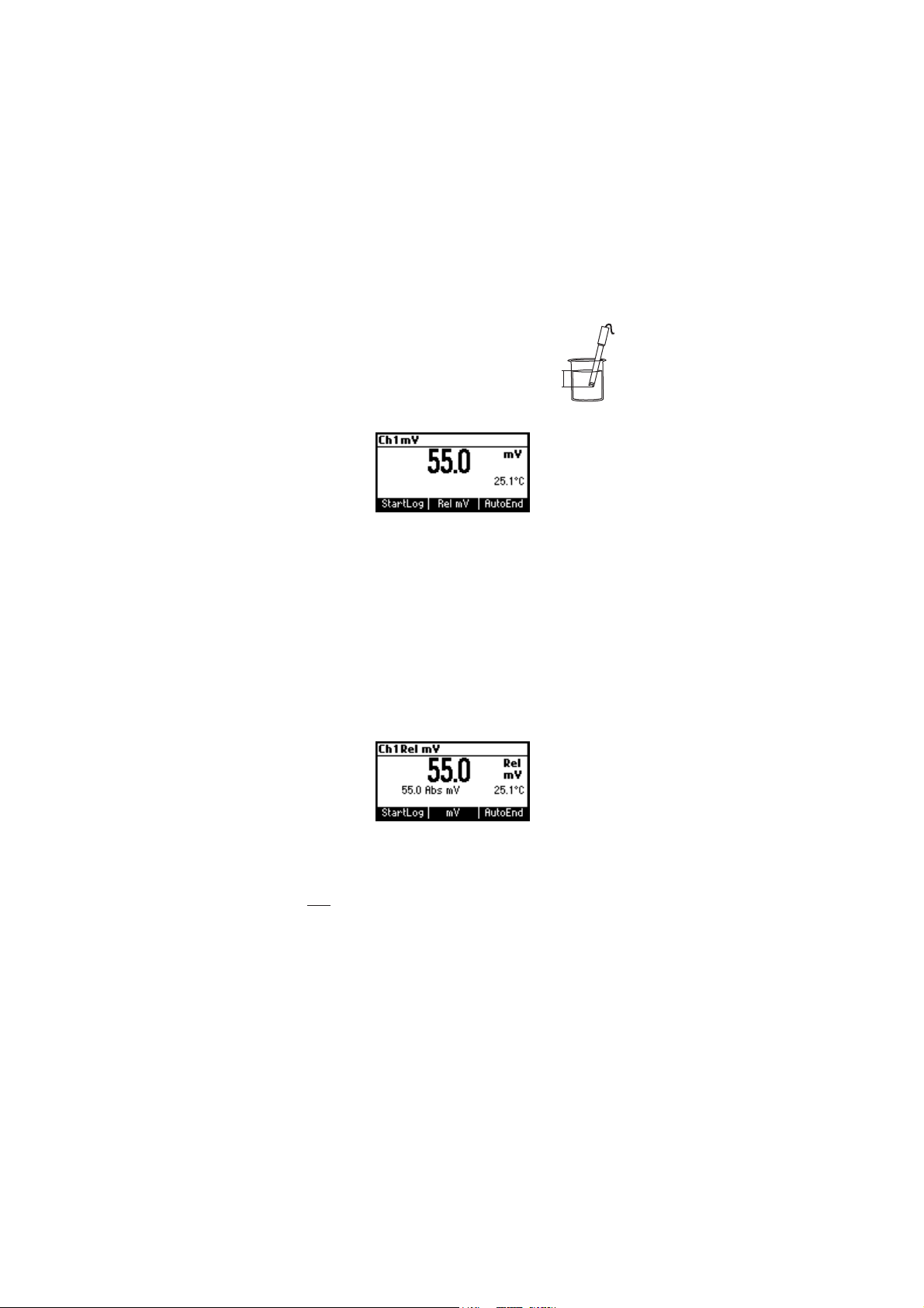
If necessary, enter the mV mode by pressing RANGE
until the display changes to mV.
Submerse the ORP electrode 3 cm (1¼”) into the
3 cm
sample to be tested and wait a few seconds for the
reading to stabilize.
Measurements are displayed with 0.1 mV resolution.
The “ATC” (or “MTC”) message is turned off because mV readings are not
temperature compensated.
For accurate ORP measurements, the surface of the electrode must be
clean and smooth. Pretreatment solutions are available to condition the
electrode and improve its response time (see ACCESSORIES section, page 77).
RELATIVE mV MEASUREMENTS
To enter Relative mV mode, press Rel mV function key while in mV
measurement mode. The relative mV reading will be displayed along
with the Absolute mV value and the current temperature readings.
The relative mV reading is equal to the difference between the absolute
mV input value and relative mV offset established in the relative mV
calibration.
Note: If using the pH or ISE electrode while in mV mode, the instrument
will measure the mV generated by the electrode.
ISE MEASUREMENTS
To perform ion concentration measurements, connect an ISE electrode
(and the corresponding reference if necessary) to the corresponding
BNC input and turn it ON.
12
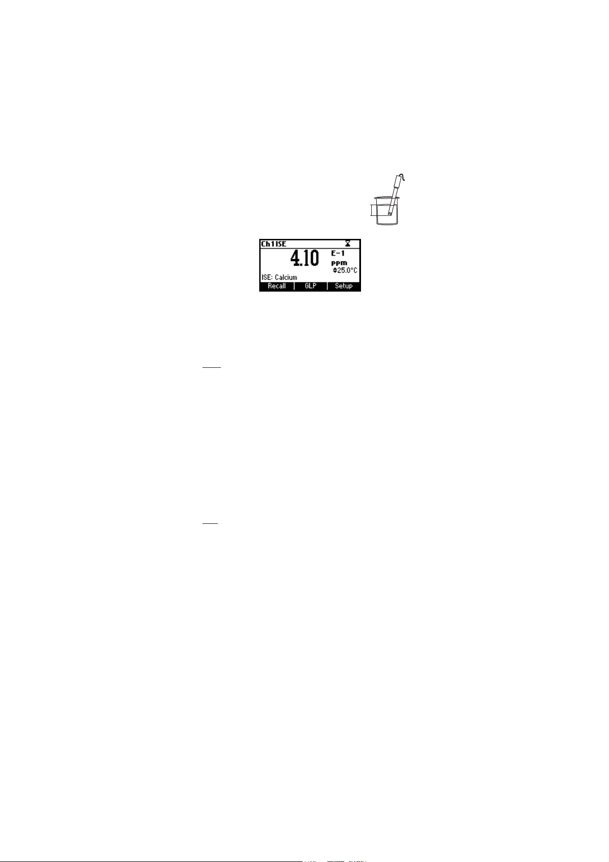
Submerse the ISE electrode tip 3 cm (1¼”) into the
sample to be tested and wait for the reading to
stabilize.
The ISE reading will be displayed along with the
3 cm
current temperature reading.
The ”ATC“(or “MTC”) message is turned off because ppm readings are
not temperature compensated.
In order to take accurate ISE measurements, make sure that the appropriate
ISE electrode type and ISE unit were set in SETUP menu and the
instrument was calibrated (see ISE CALIBRATION for details, page 29).
Notes: • When the reading is out of range, the display will flash the
closest full-scale value.
• The instrument will display “----” on the primary LCD if it is
not calibrated. Perform at least a single-point calibration in
order to take ISE measurements.
• Changing the selection in the SETUP menu for the ISE
electrode or the ISE parameter will require calibration.
TEMPERATURE MEASUREMENTS
pH channel
Connect the HI 7662-T temperature probe to the appropriate socket.
Immerse the temperature probe into the sample and allow the reading
on the secondary LCD to stabilize.
Note: The temperature can be displayed in Celsius degrees (ºC) or in
Fahrenheit degrees (ºF) (see SETUP for details, page 40).
EC/TDS/NaCl/Resistivity channel
Immerse the conductivity probe (which includes also the temperature
sensor) into the solution to be tested. The sleeve holes must be completely
submerged. Tap the probe repeatedly to remove any air bubbles that
may be trapped inside the sleeve.
If needed, press CHANNEL to select EC channel or/and press RANGE
repeatedly until the desired range (EC, Resistivity, TDS, Salt) is selected on
the LCD. If needed, select the “Automatic” or “No TC” compensation mode
to perform temperature measurements (see SETUP for details, page 40).
Allow for the reading to stabilize. The main LCD line displays the
measurement in the selected range, while the temperature is
displayed on the lower LCD line.
13
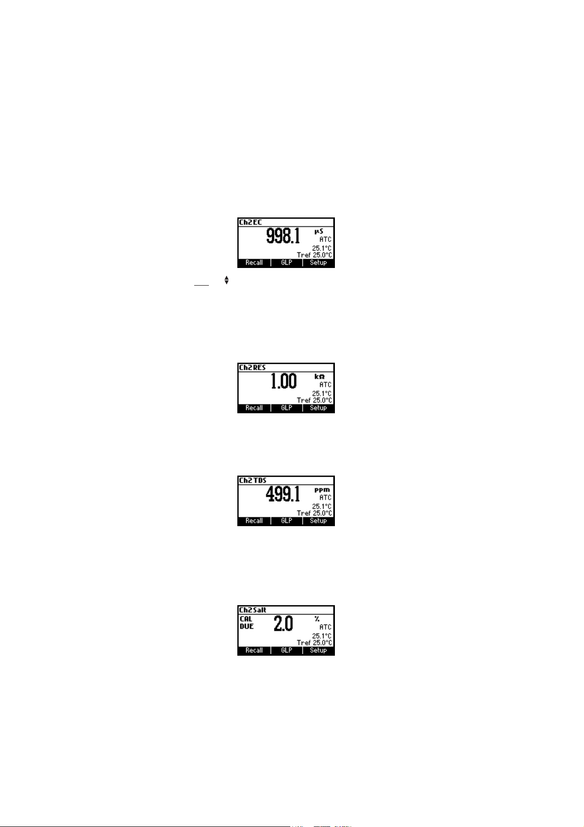
EC range
The conductivity range is from 0 to 400 mS/cm . The actual conductivity
range (the uncompensated conductivity) is up to 1000 mS/cm. The
instrument will display conductivity readings up to 1000 mS/cm.
Note: The symbol in front of the temperature reading means that the
temperature can be entered by the user (“Manual” option
selected in SETUP).
Resistivity range
The reciprocal of the conductivity of a material is the resistivity.
TDS range
A conductivity measured value can be corrected to a total disolved solids
value using the TDS factor (value entered in SETUP).
Salinity
The salinity is derived from the conductivity of a sample.
The percent of salinity in a sample is depending of the sample and on the
salinity coefficient.
14
AUTO-RANGING EC CHANNELAUTO-RANGING EC CHANNEL
AUTO-RANGING EC CHANNEL
AUTO-RANGING EC CHANNELAUTO-RANGING EC CHANNEL
The EC, Resistivity and TDS scales are auto-ranging. The meter automatically
sets the scale with the highest possible resolution.
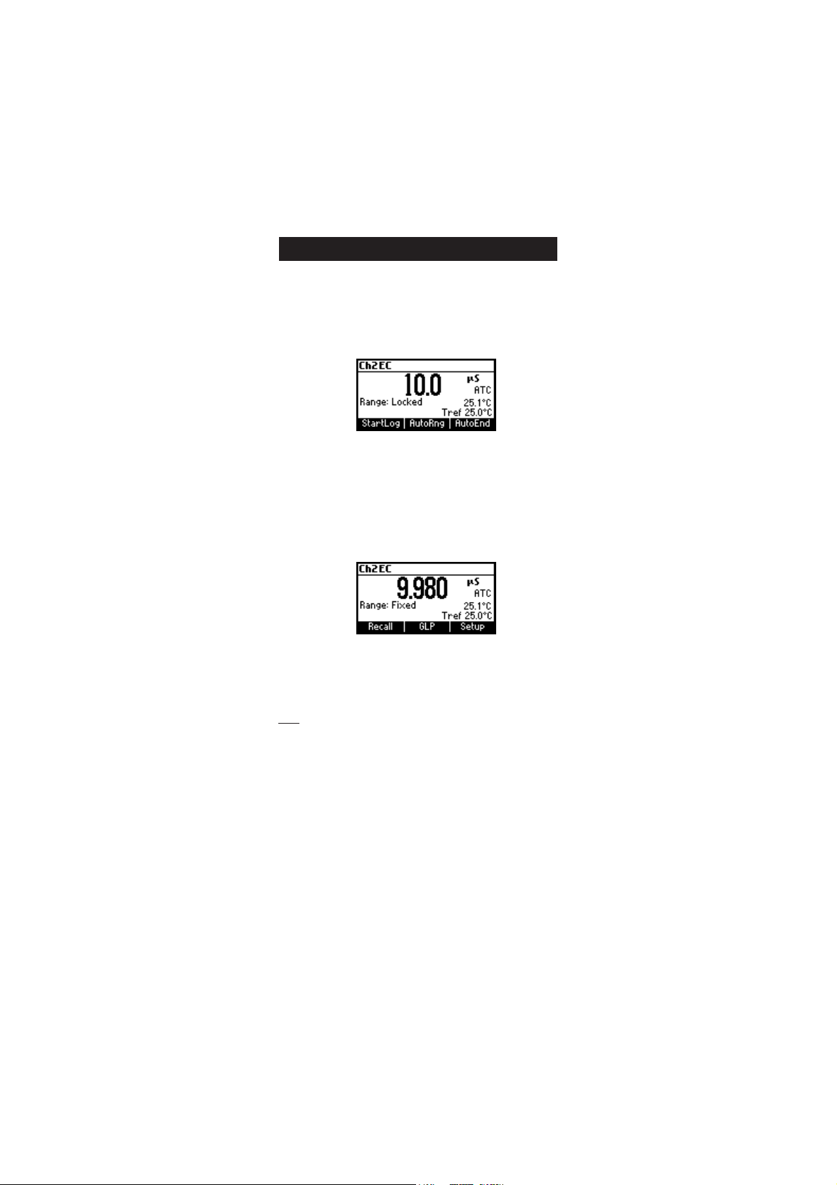
By pressing Lock, the auto-ranging feature is disabled and the current
range is frozen on the LCD.
The “Range: Locked” message is displayed. To restore the auto-ranging
option press AutoRng functional key again.
The auto-ranging mode is also disabled by selecting a “fixed range” in
the SETUP menu. While in fixed range mode the instrument will display
the readings with the fixed resolution. Maximum 6 digits can be
displayed.
The top of the fixed range is displayed blinking when the reading exceeds
this value.
To disable fixed range mode enter SETUP and select auto-ranging mode.
Note: Auto-ranging is automatically restored if the range is changed, if
the meter is turned off and back on again or if the calibration
mode is entered.
15
TEMPERATURE COMPENSATION EC CHANNELTEMPERATURE COMPENSATION EC CHANNEL
TEMPERATURE COMPENSATION EC CHANNEL
TEMPERATURE COMPENSATION EC CHANNELTEMPERATURE COMPENSATION EC CHANNEL
The conductivity of a solution with a specific electrolyte concentration
changes with temperature. The relationship of the change in conductivity
as a function of temperature is described by a solution’s temperature
coefficient. This coefficient varies with each solution and is user selectable
(see SETUP mode).
Two selectable temperature sources are available: reading directly from
the sensor inside the probe or manual entry.
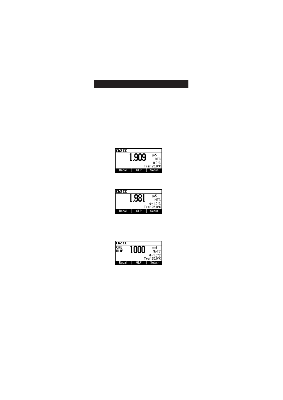
Three options of linear temperature compensation are available:
Automatic: temperature readings from the sensor inside the EC probe.
Manual: temperature entered manually by the user.
No Temperature Compensation (No TC): The temperature shown on
the LCD is not taken into account. The meter displays the actual
conductivity.
To select the desired option enter SETUP menu (see page 40).
If the temperature is out of the -20 °C - 120 °C range the instrument will
not do temperature compensation.
16

Cº Fº
0307IH
0308IH
(µ )mc/S
1307IH
1308IH
(µ )mc/S
3307IH
3308IH
(µ )mc/S
4307IH
4308IH
(µ )mc/S
5307IH
5308IH
(µ )mc/S
9307IH
9308IH
(µ )mc/S
0
5
01
51
61
71
81
91
02
12
22
32
42
52
62
72
82
92
03
13
23
14
05
95
8.06
6.26
4.46
2.66
86
8.96
6.17
4.37
2.57
77
8.87
6.08
4.28
2.48
68
8.78
0517
0228
0339
08401
02701
05901
09111
03411
07611
01911
05121
09321
04621
08821
03131
07331
02631
07831
02141
07341
677
698
0201
7411
3711
9911
5221
1521
8721
5031
2331
9531
6831
3141
0441
7641
4941
1251
8451
5751
46
56
76
86
07
17
37
47
67
87
97
18
28
48
68
78
98
09
29
49
00384
00535
00695
00456
00276
00586
00896
00317
00427
00047
00257
00567
00387
00008
00318
00038
00948
00368
00288
00009
00456
00147
00238
00529
00449
00369
00289
002001
001201
000401
009501
009701
008901
008111
008311
007511
007711
007911
008121
009321
0672
0813
5163
3604
5514
5424
7334
9244
3254
7164
1174
5084
2094
0005
6905
0915
6825
3835
9745
5755
CONDUCTIVITY VERSUSCONDUCTIVITY VERSUS
CONDUCTIVITY VERSUS
CONDUCTIVITY VERSUSCONDUCTIVITY VERSUS
TEMPERATURE CHARTTEMPERATURE CHART
TEMPERATURE CHART
TEMPERATURE CHARTTEMPERATURE CHART
The conductivity of an aqueous solution is the measure of its ability to
carry an electrical current by means of ionic motion.
The conductivity invariably increases with increasing temperature.
It is affected by the type and number of ions in the solution and by the
viscosity of the solution itself. Both parameters are temperature dependent.
The dependency of conductivity on temperature is expressed as a relative
change per Celsius degree at a particular temperature, commonly as
percent per ºC.
The following table lists the temperature dependence of the HANNA
calibration buffers.
BACKLIGHT FEATURE
The instrument is provided with a Backlight feature. The Backlight levels
can be selected in the SETUP menu.
17

USERUSER
CALIBRATION CALIBRATION
USER
CALIBRATION
USERUSER
CALIBRATION CALIBRATION
To enter User Calibration screen press CAL key while in pH/Rel mV/ISE
range (pH channel) or EC/Salinity range (EC channel).
From EC range
Press the corresponding functional key to enter:
• EC user calibration.
• Ch2 temperature user calibration.
From pH range
Press the corresponding functional key to enter:
• pH user calibration.
• Ch1 temperature user calibration.
Note: For REL mV, ISE or Salinity range, pressing CAL on the selected
range will cause the meter to enter directly in calibration mode.
18

pp
H CALIBRATIONH CALIBRATION
p
H CALIBRATION
pp
H CALIBRATIONH CALIBRATION
It is recommended to calibrate the instrument frequently, especially if
high accuracy is required.
The pH range should be recalibrated:
• Whenever the pH electrode is replaced.
• At least once a week.
• After testing aggressive chemicals.
• When calibration alarm time out is expired - “CAL DUE” blinks (if
feature is enabled in SETUP).
• If “Out of cal. range” message appears on the LCD during pH
measurement (the measurement range is not covered by current
calibration, if this feature is enabled in SETUP).
PROCEDURE
The HI 3512 offers a choice of 7 standard buffers (1.68, 4.01, 6.86,
7.01, 9.18, 10.01 and 12.45 pH) and up to 2 custom buffers. The
standard pH buffers are temperature compensated during calibration.
The custom, user entered buffers are not temperature compensated
during calibration.
When a custom buffer is selected during calibration, the Custom function
key is displayed on the LCD. Press Custom key in order to alter the value
to the actual pH value at the temperature of measurement. Use
ARROW keys to change the value within a ±1.00 pH window and
then press Accept. Press ESC to leave custom buffers value unchanged.
Press Confirm.
For accurate pH measurements, it is recommended to perform a multipoint
calibration. At least a two-point calibration is required.
The instrument will automatically skip the buffers within ±0.2 pH
window, around one of the calibrated buffers.
• Pour small quantities of selected buffer solutions into clean beakers.
For accurate calibration use two beakers for each buffer solution, the
first one for rinsing the electrode and the second one for calibration.
• Remove the protective cap, open the fill hole and rinse the electrode
with some of the buffer solution to be used for the first calibration
point.
19

FIVE-POINT CALIBRATIONFIVE-POINT CALIBRATION
FIVE-POINT CALIBRATION
FIVE-POINT CALIBRATIONFIVE-POINT CALIBRATION
• Immerse the pH electrode and the temperature
probe approximately 3 cm (1¼”) into a buffer
solution of your
7.01, 9.18, 10.01, 12.45 or a custom buffer)
choice (pH 1.68, 4.01, 6.86,
3 cm
and stir the buffer gently. The temperature probe
should be close to the pH electrode.
• Enter pH calibration. The instrument will display the measured pH,
the LCD first expected buffer and the temperature reading.
• If necessary, press the ARROW keys to select a different buffer value.
• The “ ” tag will blink on the LCD until the reading is stable.
• When the reading is stable and close to the selected buffer, Confirm
function key is displayed.
• Press Confirm to confirm first point.
• The calibrated value and the second expected buffer value is then
displayed on the LCD.
• After the first calibration point is confirmed, immerse the pH electrode
and the temperature probe approximately 3 cm (1¾”) into the
second buffer solution and stir gently. The temperature probe should
be close to the pH electrode.
• If necessary, press the ARROW keys to select a different buffer value.
• The “ ” tag will blink on the LCD until the reading is stable.
20
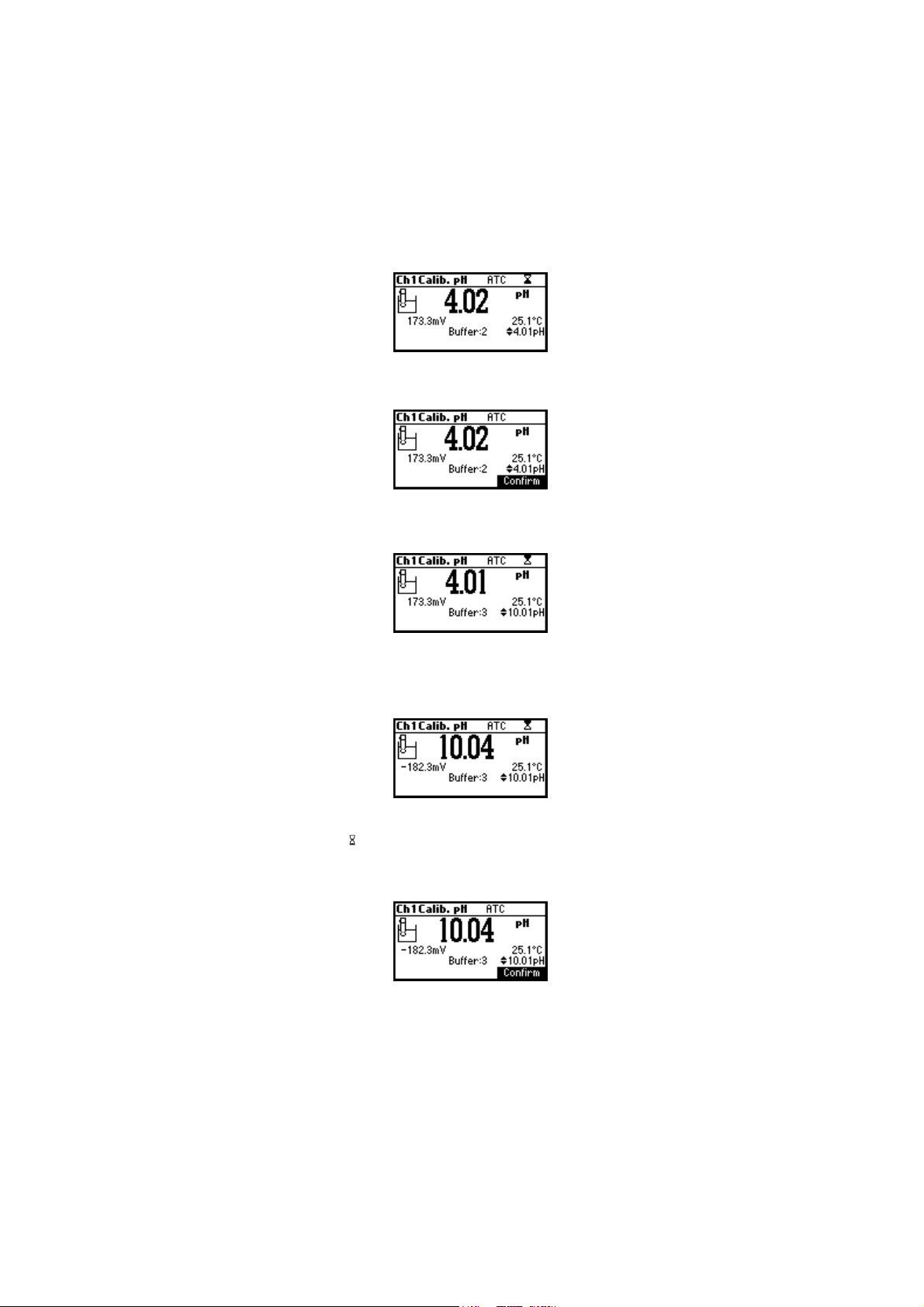
• When the reading is stable and close to the selected buffer, the
Confirm function key is displayed.
• Press Confirm to confirm calibration.
• The calibrated value and the third expected buffer value will be
displayed.
• After the second calibration point is confirmed, immerse the pH
electrode and the temperature probe approximately 3 cm (1¾”) into
a third buffer solution and stir gently. The temperature probe should
be close to the pH electrode.
• If necessary, press the ARROW keys to select a different buffer value.
• The “ ” tag will blink on the LCD until the reading is stable.
• When the reading is stable and close to the selected buffer, the
Confirm function key is displayed.
• Press Confirm to confirm calibration.
Repeat this procedure with two additional pH buffers to encompass the
entire sample pH range.
21
FOUR, THREE or TWO-POINT CALIBRATION
• Proceed as described in “FIVE-POINT CALIBRATION” section.
• Press ESC after the appropriate accepted calibration point. The
instruments will return to calibration screen and will memorize the
calibration data.
SINGLE-POINT CALIBRATION
There are two selectable options for a single-point calibration:
Replace and Offset.
This option is configured in SETUP mode under the parameter First Point
Mode. In both cases the meter will alter the present calibration data in
the instrument. If “Replace” is selected a new calibration point will be
added to the existing data, and the slope is calculated. The slopes
between current buffer and nearest lower and higher buffers will be
reevaluated.
If the “Offset” option is selected, an electrode offset correction is
performed to all buffer data keeping the existing slopes unchanged.
• Proceed as described in “FIVE-POINT CALIBRATION” section.
• Press ESC after the first calibration point was confirmed. The instruments
will memorize the single-point calibration data and will return to
calibration screen.
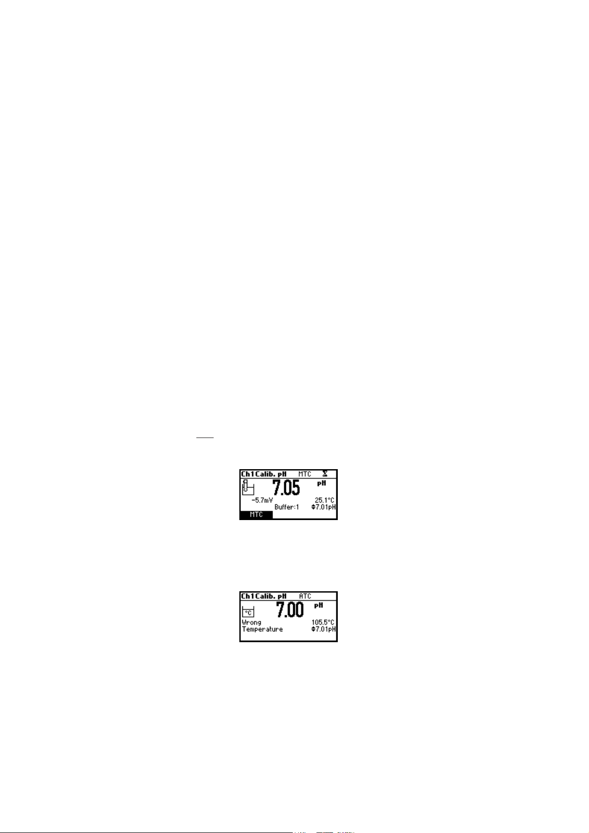
Notes: • Press MTC key to toggle between pH buffer selection and the
temperature reading during calibration while temperature
probe is disconnected (MTC mode).
• The displayed arrow is moving to the temperature value.
Use ARROW keys in order to change the temperature.
ERROR SCREENS
Wrong temperature
The calibration cannot be confirmed.
If the temperature is less than 0 °C or greater than 100 °C during
calibration, the calibration cannot be confirmed.
22
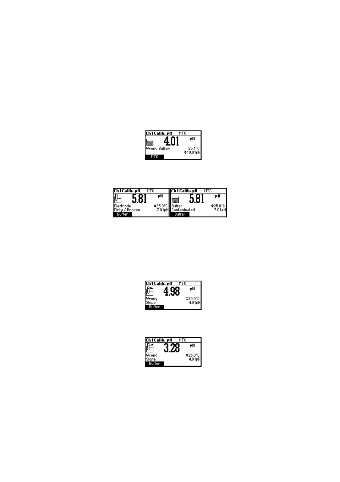
Wrong buffer
The calibration cannot be confirmed.
The pH reading is not close to the selected buffer. Select another buffer
using the ARROW keys or change the buffer.
“Electrode Dirty/Broken“ alternatively with “Buffer Contaminated“.
The calibration cannot be confirmed.
The offset of the electrode is not in the accepted range. Check if the
electrode is broken or clean it following the CLEANING PROCEDURE (see
page 74). Check the quality of the buffer. If necessary, change the
buffer.
Wrong slope
The calibration cannot be confirmed.
The evaluated slope is less than the lowest accepted value (80% of
default slope).
The evaluated slope is more than the highest accepted value (110 % of
default slope).
23

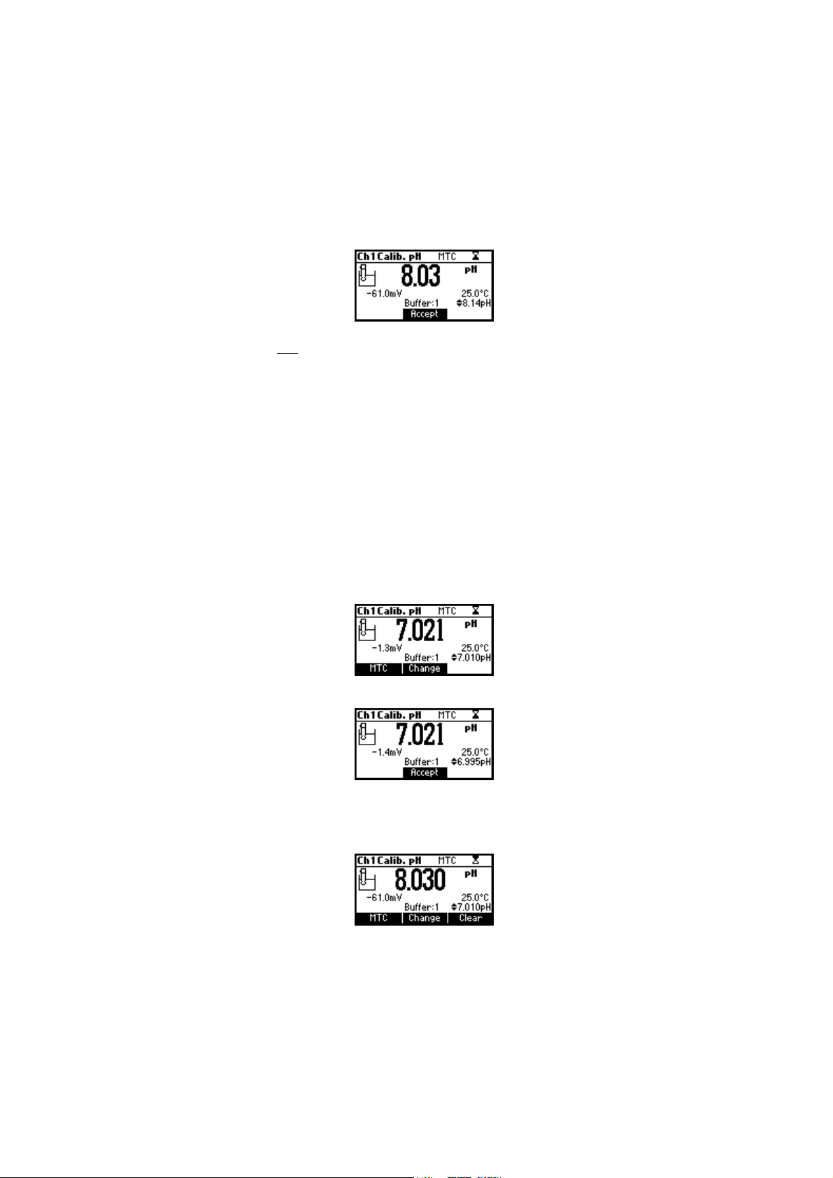
Wrong old slope
An inconsistency between new and previous (old) calibration is detected.
Clear old calibration parameters and initiate calibration from the current
point. The instrument will keep all confirmed values during current
calibration.
Note: For single-point calibration the electrode condition is not displayed
in the measurement screen.
Each time a buffer is confirmed, the new calibration parameters replace
the older calibration parameters of the corresponding buffer.
If an additional single buffer calibration is added at a latter time, the
new buffer point will be added to the stored calibration.
If the existing stored calibration is full (five calibration points), after
confirming the calibration point, the instrument will ask which buffer will
be replaced by current buffer. On the Buffer line will be displayed the
proposed buffer.
Press ARROW keys to select another buffer to be replaced.
Press Confirm to confirm the buffer that will be replaced.
Press ESC to exit mode. In this case, the buffer will not be entered.
Note: The replaced buffer is not removed from calibration list and it can
be selected for the next calibration points.
WORKING WITH CUSTOM BUFFERS
If at least one custom buffer was set in SETUP menu, it can be selected
for calibration by pressing the ARROW keys. The Custom function key
will be displayed.
Press Custom if you want to adjust the buffer to its value at the current
temperature.
24
Use the ARROW keys to change the buffer value.
Press Accept to accept new value or ESC to exit mode.
Note: Custom buffer value can be adjusted within a ±1.00 pH window,
around the set value.
WORKING WITH MILI pH BUFFERS
HANNA millesimal pH buffers are ± 0.002 pH buffers formulated to
correspond to nominal pH values. (1.000, 2.000, 3.000, 4.010, 5.000,
6.000, 7.010, 8.000, 9.000, 10.010, 11.000, 12.000, 13.000 and 9
that fall between). These buffers require the user to use the closest
standard buffer and adjust it, or to use custom buffers. With these buffers
it is possible to closely bracket the measurement range of interest and
insure an accurate measurement.
The resolution of the meter must be set to 0.001 pH (see SETUP on page 40).
Eight buffers are stored in instrument for calibration.
If calibration is invoked using millesimal buffers, the calibration buffer
can be modified within a ±0.020 pH range in accordance with the
label on the calibration buffer.
Press Change to enter buffer adjust mode.
Use ARROW keys to change the buffer value.
Press Accept to accept new value or ESC to exit adjusting mode.
CLEAR CALIBRATION
Press Clear function key when displayed to clear previous calibrations.
25
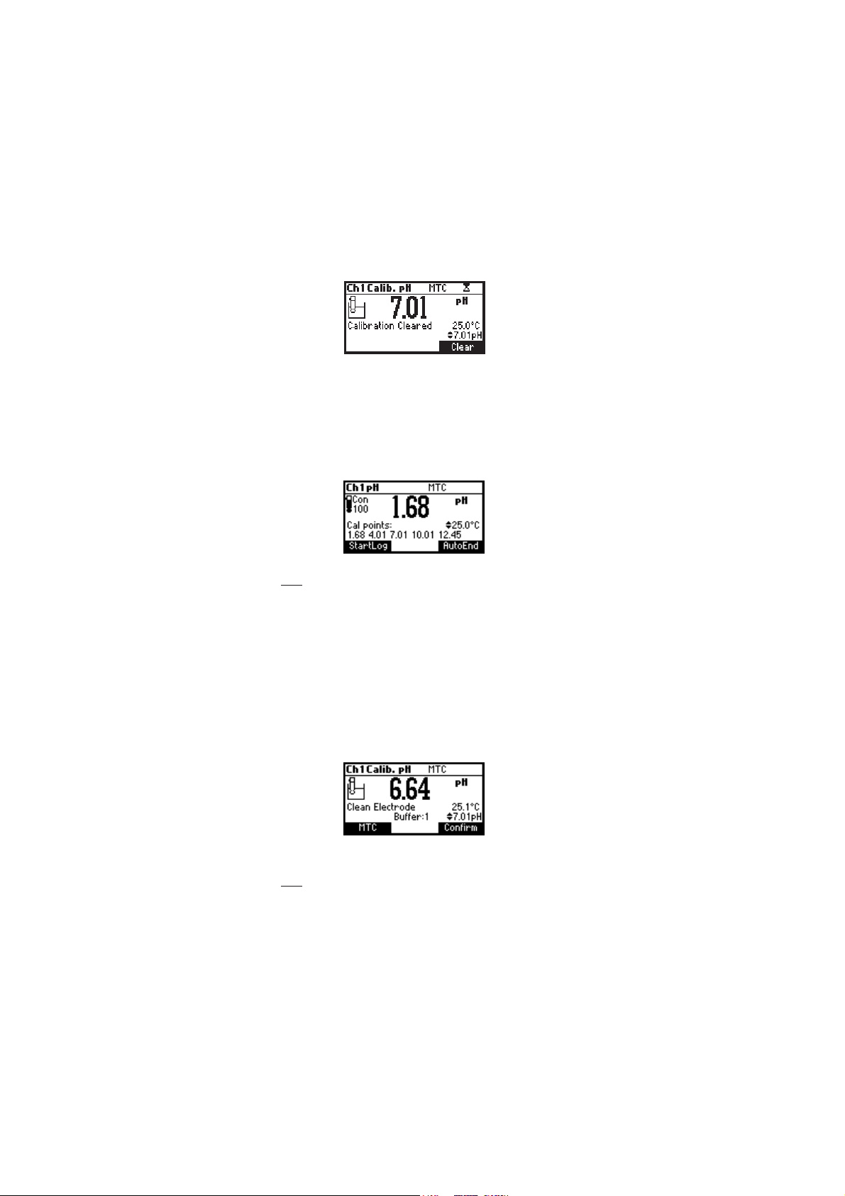
The instrument will display “Calibration Cleared” and the instrument
returns to measuring mode.
ELECTRODE CONDITION
The display is provided with an icon, and a numeric value (unless the
feature is disabled) which gives an indication of the electrode status after
calibration.
The indication remains active until the end of the calibration day.
Note: The electrode condition is evaluated only if current calibration
includes at least two standard buffers.
CLEAN ELECTRODE WARNING
Each time pH calibration is performed, the instrument internally
compares the new calibration with the one previously stored.
When this comparison indicates a significant difference, the “Clean
Electrode” warning message is displayed to advise the user that the pH
electrode may need to be cleaned (see ELECTRODE CONDITIONING &
MAINTENANCE section for details, page 72).
After cleaning, perform a new calibration.
Note: If the calibration data are cleared, the comparison is done with
the default values.
26
 Loading...