


Instruction Manual
HI 9829
Multiparameter Meter
With available GPS, logging probe, turbidity
and ion measurements
w w w . h a n n a i n s t . c o m
1
2

Dear Customer,
Thank you for choosing a HANNA instruments® product.
Please read this instruction manual carefully before using the instrument. It will provide you with the necessary information for correct use of the instrument, as well as it’s versatility.
If you need additional technical information, do not hesitate to e-mail us at tech@hannainst.com or visit our website www.hannainst.com for our worldwide contact list.
This instrument is in compliance with the 
 directives.
HANNA instruments® reserves the right to modify the design, construction and appearance of its products without advance notice.
3

TABLE OF CONTENTS |
|
CHAPTER 1- INTRODUCTION |
|
1.1 Preliminary Examination ................................................................................. |
6 |
1.2 Model Identification ....................................................................................... |
6 |
1.3 General Description....................................................................................... |
6 |
1.4 Display and Keypad Description ...................................................................... |
8 |
CHAPTER 2 - QUICK START |
|
2.1 Sensor and Probe Installation .......................................................................... |
9 |
2.2 Basic Operation ........................................................................................... |
10 |
2.3 Help Function .............................................................................................. |
11 |
CHAPTER 3 - SPECIFICATIONS |
|
3.1 System Specifications ..................................................................................... |
12 |
3.2 Probe Specifications ...................................................................................... |
17 |
3.3 Sensor Specifications ..................................................................................... |
18 |
CHAPTER 4 - PROBE INSTALLATION |
|
4.1 Sensor Descriptions ....................................................................................... |
19 |
4.2 Sensor Preparation/Activation ........................................................................ |
21 |
4.3 Sensor Installation ........................................................................................ |
23 |
CHAPTER 5 - INITIALIZATION AND MEASUREMENT |
|
5.1 Battery Installation ........................................................................................ |
25 |
5.2 Meter Initialization ........................................................................................ |
28 |
5.3 Measurement Mode ...................................................................................... |
29 |
5.4 Setup Menu Structure .................................................................................... |
30 |
CHAPTER 6 - PARAMETER SETUP MENU |
|
6.1 Select Parameters .......................................................................................... |
31 |
6.2 Parameter Units ............................................................................................ |
31 |
6.3 Parameter Coefficients ................................................................................... |
33 |
6.4 Averaging ................................................................................................... |
34 |
6.5 Turbidity Averaging ....................................................................................... |
34 |
CHAPTER 7 - CALIBRATION MODE ................................................................ |
35 |
7.1 Quick Calibration ........................................................................................ |
36 |
7.2 pH Calibration ............................................................................................. |
38 |
7.3 ISE Calibration ............................................................................................. |
41 |
4
7.4 ORP Calibration .......................................................................................... |
42 |
7.5 Dissolved Oxygen Calibration ........................................................................ |
43 |
7.6 Conductivity Calibration ................................................................................ |
45 |
7.7 Turbidity Calibration ...................................................................................... |
49 |
7.8 Temperature Calibration ................................................................................ |
51 |
7.9 Atmospheric Pressure Calibration ................................................................... |
52 |
CHAPTER 8 - SYSTEM SETUP |
|
8.1 Meter Setup ................................................................................................. |
53 |
8.2 Probe Setup ................................................................................................. |
56 |
CHAPTER 9 - GPS MENU (optional) ............................................................... |
57 |
CHAPTER 10 - STATUS |
|
10.1 Meter Status ............................................................................................... |
59 |
10.2 Probe Status ............................................................................................... |
59 |
10.3 GLP Data .................................................................................................. |
60 |
CHAPTER 11 - LOGGING MODE ................................................................... |
64 |
11.1 Logging menu structure ............................................................................... |
66 |
11.2 Logging on Meter ....................................................................................... |
66 |
11.3 Probe Log .................................................................................................. |
68 |
11.4 Log Recall ................................................................................................. |
69 |
11.5 Log Notes .................................................................................................. |
71 |
CHAPTER 12 - PC CONNECTION |
|
12.1 Software Installation .................................................................................... |
74 |
12.2 Meter to PC Connection .............................................................................. |
74 |
12.3 Probe to PC Connection .............................................................................. |
76 |
CHAPTER 13 - TROUBLESHOOTING / ERROR MESSAGES ............................... |
78 |
APPENDIX |
|
A - PROBE MAINTENANCE ................................................................................ |
81 |
B - PROBE DEPLOYMENT .................................................................................. |
84 |
C - ISE INFORMATION ...................................................................................... |
89 |
D - ACCESSORIES ............................................................................................. |
95 |
E - WARRANTY ............................................................................................... |
101 |
5

Chapter 1 - INTRODUCTION
1.1 PRELIMINARY EXAMINATION
Remove the instrument from the packing material and examine it carefully to make sure that no damage has occurred during shipping. If there is any damage, notify your Dealer or the nearest HANNA Customer Service Center immediately.
Note Save all packing materials until you are sure that the instrument functions correctly. Any damaged or defective items must be returned in their original packing material with the supplied accessories.
1.2 MODEL IDENTIFICATION
Meter: There are two models for the meter:
HI 9829: Portable multiparameter meter
HI 98290: Portable multiparameter meter with GPS Probe: There are two base models of multiparameter probes:
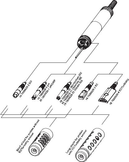
HI 7609829: Standard multiparameter probe
HI 7629829: Multiparameter probe with autonomous logging capability
All meters and probes are fully compatible with each other, and all available measurement sensors can be used on both probe models.
Different combinations of meters, probes, sensors and accessories can be ordered either in predefined configurations or individually. See Appendix D for ordering configurations.
For example, ordering codes of probes follow:
HI 7609829/X is a HI 7609829 probe with X meter cable for pH/pH+ORP/ ISE, D.O., EC, temperature sensors with a short probe shield
HI 7619829/X is a HI 7609829 probe with X meter cable for pH/pH+ORP/ ISE, D.O., EC+turbidity, temperature sensors with a long probe shield
HI 7629829/X is a HI 7629829 logging probe with X meter cable for pH/ pH+ORP/ISE, D.O., EC, temperature sensors with a short probe shield
HI 7639829/X is a HI 7629829 logging probe with X meter cable for pH/ pH+ORP/ISE, D.O., EC+turbidity, temperature sensors with a long probe shield
1.3 GENERAL DESCRIPTION
HI 9829 is a portable logging multiparameter system that monitors up to 14 different water quality parameters (7 measured, 7 calculated).
The microprocessor-based intelligent multisensor probe allows measurement of many water quality parameters such as pH, ORP, turbidity, dissolved oxygen,
6
conductivity, chloride, nitrate, ammonium and temperature with data logging. The system is easy to setup and easy to use.
The HI 98290 with GPS option has a built-in 12 channel GPS receiver and antenna that guarantees a position accuracy of 10 m (30 ft). Measurements from specific locations are tracked with detailed coordinate information that can be viewed immediately on the display.
GPS information can be transferred to a PC using HANNA’s HI 929829 software. GPS information can also be viewed using a GPS mapping software such as Google™ Maps. Clicking on visited locations using a mapping software displays the measurement information.
All HI 9829 are equipped with Fast Tracker™ an invaluable tool for associating measurements with their locations. HANNA’s exclusive Fast Tracker™—T.I.S. (Tag ID System) uses iButton®s that can be installed at any number of sampling sites. The HI 9829 features a graphic, backlit display that automatically sizes the digits to fit the screen with on-screen graphing capability. Each parameter is fully configurable.
HI 9829 was designed to withstand harsh environments and is the ideal solution for field measurements of lakes, rivers and sea.
The meter meets IP67 standards (30 minute immersion at a depth of 1 m) and the multisensor probe meets IP68 standards (continuous immersion in water). Settings and logged data can be protected with a passcode to avoid unauthorized modifications and context-sensitive help is always available.
Main features of the HI 9829 system:
•Rugged meter and probe
•Easy to use
•Measure up to 16 parameters and display of up to 12 parameters
•Tracking of measurement locations with GPS (optional)
•Waterproof protection (IP67 for the meter and IP68 for the probe)
•Exclusive Fast Tracker™—T.I.S. (Tag ID System)
•Graphic LCD with backlight
•Built-in barometer for D.O. concentration compensation
•Quick calibration feature
•Measurement check to eliminate any erroneous readings
•Autorecognition of probe and sensors
•Log-on-demand and automatic logging (up to 45,000 samples) on meter for all parameters
•Graphical display of logged data
GOOGLE™ is a registered trademark of Google, Inc. HANNA instruments® has no affiliation with Google™, Inc. iButton® is a registered trademark of Maxim/Dallas Semiconductor Corp.
7

•USB interface for PC communication
•Auto-ranging for EC, ISE and turbidity readings
•Good Laboratory Practice feature, the last 5 calibrations are automatically stored
•Field-replaceable sensors with color coded caps
•Meter can be powered with either alkaline or rechargeable batteries
•Fast charging capability
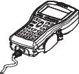
1.4 DISPLAY & KEYBOARD DESCRIPTION
1.Graphic LCD
2.Battery level indicator
3. Softkey functions
4.Left softkey: function defined on display
5.On/Off key: turn the meter on and off
6.Lamp key: turn the backlight on and off
7.Alphanumeric keyboard: insert alphanumeric codes
8.HELP key: obtain information about the displayed screen
9.Arrow keys: scroll the displayed options/message
10.ESC key: return to the previous screen
11.Right softkey: function defined on display
12.GPS signal strength indicator (optional)
13.Tag reader
8

Chapter 2 - QUICK START
Before you begin using the HI 9829 multiparameter system, either charge the included rechargeable C batteries for at least 6 hours or replace the rechargeable batteries with non-rechargeable alkaline batteries.
2.1 SENSOR AND PROBE INSTALLATION
•Sensor o-rings must be lubricated with the supplied grease prior to installation.
•HI 76x9829 probes have 3 sensor connectors identified with colorcoded triangles:
•Connector 1 (red): For either pH/ORP, pH, ammonium, chloride or nitrate sensor
•Connector 2 (white): For dissolved oxygen sensor
•Connector 3: (blue): For either EC or EC/turbidity sensor
•Position the connector key towards the center of the probe, make sure the connector is seated correctly (the sensor will no longer move freely) before tightening the locking threads.
•To protect the sensors, screw the protective shield onto the probe body.
•Unscrew the battery cover of the HI 7629829 logging probe and install 4 AA batteries for autonomous logging before connecting to the meter.
•With the meter off, connect the probe to the DIN socket on the bottom of the meter. Align the pins and key then push the plug into the socket and tighten the thread.
•Turn the meter on by pressing the ON/OFF key. The meter will automatically recognize the probe and the installed sensors and identify them on the probe status screen.
•Press <Measure> to view the measurement screen.
9

2.2 BASIC OPERATION
The main operating modes for HI 9829 are measurement, logging and setup.
The measurement screen can be configured to display a single measurement or up to 12 simultaneous measurements by using the numbers 1-7 on the keypad. Use the arrow keys to scroll through the measurements not being displayed. See section 5.3 for more details.
The measurement units will blink if the system has not been calibrated and the measurement number will blink when the reading is out of range.
10
Press <Log> to display the logging menu. You can either log a single sample on the meter, start an interval log on the meter, or start an interval log on a logging probe (HI 7629829). See chapter 11 for more details.
Press <Menu> to enter setup mode. You can configure which parameters you want to measure, calibrate the sensors, change system settings, access the GPS menu and view the meter and probe status.
2.3 HELP FUNCTION
HI 9829 features context sensitive HELP, which provides useful information regarding the displayed screen.
Simply press the HELP key to access this function, then use the arrow keys to scroll through the message.
To escape from the HELP window, press the HELP key again or ESC.
11

Chapter 3 - SPECIFICATIONS
3.1 SYSTEM SPECIFICATIONS
TEMPERATURE
Range |
-5.00 to 55.00 °C; |
|
23.00 to 131.00 °F; |
|
268.15 to 328.15 K |
|
|
Resolution |
0.01 °C; 0.01 °F; 0.01 K |
|
|
Accuracy |
± 0.15 °C; ± 0.27 °F; ±0.15 K |
|
|
Calibration |
Automatic at 1 custom point |
pH/mV |
|
|
|
Range |
0.00 to 14.00 pH; ± 600.0 mV |
|
|
Resolution |
0.01 pH; 0.1 mV |
|
|
Accuracy |
± 0.02 pH; ± 0.5 mV |
|
|
Calibration |
Automatic 1, 2 or 3 points with automatic recognition |
|
of 5 standard buffers (pH 4.01, 6.86, 7.01, 9.18, 10.01) |
|
and 1 custom buffer |
|
|
ORP |
|
|
|
Range |
± 2000.0 mV |
|
|
Resolution |
0.1 mV |
|
|
Accuracy |
± 1.0 mV |
|
|
Calibration |
Automatic at 1 custom point (relative mV) |
|
|
DISSOLVED OXYGEN |
|
|
|
Range |
0.0 to 500.0 % |
|
0.00 to 50.00 ppm (mg/L) |
|
|
Resolution |
0.1 % |
|
0.01 ppm (mg/L) |
|
|
Accuracy |
0.0 to 300.0 %: ± 1.5 % of reading |
|
or ± 1.0 % whichever is greater; |
300.0to 500.0 %: ± 3 % of reading
0.00to 30.00 ppm (mg/L): ± 1.5 % of reading or ±0.10 ppm (mg/L) whichever is greater;
30.00ppm (mg/L) to 50.00 ppm (mg/L): ± 3 % of reading
Calibration |
Automatic 1 or 2 points at 0, 100 % or 1 custom point |
12

CONDUCTIVITY
Range 0 to 200 mS/cm (absolute EC up to 400 mS/cm)
Resolution
Manual 1 µS/cm; 0.001 mS/cm; 0.01 mS/cm; 0.1 mS/cm; 1 mS/cm Automatic 1 µS/cm from 0 to 9999 µS/cm
0.01 mS/cm from 10.00 to 99.99 mS/cm
0.1 mS/cm from 100.0 to 400.0 mS/cm Automatic (mS/cm) 0.001 mS/cm from 0.000 to 9.999 mS/cm
0.01 mS/cm from 10.00 to 99.99 mS/cm
0.1 mS/cm from 100.0 to 400.0 mS/cm
Accuracy |
±1 % of reading or ±1 µS/cm whichever is greater |
|
|
|
|
Calibration |
Automatic single point, with 6 standard solutions |
|
|
(84 µS/cm, 1413 µS/cm, 5.00 mS/cm, 12.88 mS/cm, |
|
|
|
80.0 mS/cm, 111.8 mS/cm) or custom point |
|
|
|
RESISTIVITY |
|
|
|
|
|
Range |
|
0 to 999999 Ω ·cm; |
(depending on measurement setup) |
0 to 1000.0 kΩ ·cm; |
|
|
|
0 to 1.0000 MΩ ·cm |
Resolution |
|
Depending on resistivity reading |
|
|
|
Calibration |
|
Based on conductivity or salinity calibration |
|
||
TDS (Total Dissolved Solids) |
||
|
|
|
Range |
|
0 to 400000 ppm (mg/L); |
|
|
(the maximum value depends on the TDS factor) |
|
|
|
Resolution |
|
|
Manual |
|
1 ppm (mg/L); 0.001 ppt (g/L); |
|
|
0.01 ppt (g/L); 0.1 ppt (g/L); 1 ppt (g/L) |
Automatic |
|
1 ppm (mg/L) from 0 to 9999 ppm (mg/L) |
|
|
0.01 ppt (g/L) from 10.00 to 99.99 ppt (g/L) |
|
|
0.1 ppt (g/L) from 100.0 to 400.0 ppt (g/L) |
Automatic ppt (g/L) |
|
0.001 ppt (g/L) from 0.000 to 9.999 ppt (g/L) |
|
|
0.01 ppt (g/L) from 10.00 to 99.99 ppt (g/L) |
|
|
0.1 ppt (g/L) from 100.0 to 400.0 ppt (g/L) |
|
|
|
Accuracy |
±1 % of reading or ±1 ppm (mg/L) whichever is greater |
|
|
|
|
Calibration |
|
Based on conductivity or salinity calibration |
|
|
|
13

|
SALINITY |
|
|
Range |
0.00 to 70.00 PSU |
Resolution |
0.01 PSU |
|
|
|
|
Accuracy |
±2% of reading or ±0.01 PSU whichever is greater |
|
|
|
|
Calibration |
Based on conductivity calibration |
|
|
|
|
|
SEAWATER SIGMA |
|
|
|
|
|
Range |
0.0 to 50.0 σ t, σ 0, σ 15 |
Resolution |
0.1 σ t, σ 0, σ 15 |
|
Accuracy |
± 1σ t, σ 0, σ 15 |
|
Calibration |
Based on conductivity or salinity calibration |
|
|
|
|
|
TURBIDITY |
|
|
|
|
|
Range |
0.0 to 99.9 FNU; |
|
|
100 to 1000 FNU |
|
|
|
|
Resolution |
0.1 FNU from 0.0 to 99.9 FNU |
|
|
1 FNU from 100 to 1000 FNU |
|
|
|
|
Accuracy |
±0.3 FNU or ±2 % of reading, |
|
|
whichever is greater |
Calibration Automatic 1, 2 or 3 points at 0, 20 and 200 FNU, or custom
ISE
Ammonium-Nitrogen
Range |
0.02 to 200.0 ppm Am (as NH4+-N) |
|
Resolution |
0.01 ppm to 1 ppm |
|
|
|
0.1 ppm to 200.0 ppm |
|
|
|
|
Accuracy |
±5 % of reading or 2 ppm |
|
|
|
Calibration |
1 or 2 point, 10 ppm and 100 ppm |
|
|
|
|
|
Chloride |
|
Range |
0.6 to 200.0 ppm Cl (as Cl-) |
|
Resolution |
0.01 ppm to 1 ppm |
|
|
|
0.1 ppm to 200.0 ppm |
|
|
|
Accuracy |
±5 % of reading or 2 ppm |
|
|
|
|
Calibration |
1 or 2 point, 10 ppm and 100 ppm |
|
14

Nitrate-Nitrogen
Range |
0.62 to 200.0 ppm Ni (as NO --N) |
|
|
|
3 |
Resolution |
0.01 ppm to 1 ppm |
|
|
|
0.1 ppm to 200 ppm |
|
|
|
Accuracy |
±5 % of reading or 2 ppm |
|
|
|
|
Calibration |
1 or 2 point, 10 ppm and 100 ppm |
|
|
ATMOSPHERIC PRESSURE |
|
|
|
|
|
Range |
450 to 850 mm Hg; 17.72 to 33.46 in Hg; |
|
|
600.0 to 1133.2 mbar; 8.702 to 16.436 psi; |
|
|
0.5921 to 1.1184 atm; 60.00 to 113.32 kPa |
|
Resolution |
0.1 mm Hg; 0.01 in Hg; 0.1 mbar |
|
|
0.001 psi; 0.0001 atm; 0.01 kPa |
|
|
|
|
Accuracy |
±3 mm Hg within ±15°C from calibration temperature |
|
|
|
Calibration |
Automatic at 1 custom point |
|
|
|
|
METER SPECIFICATIONS
Temperature Compensation Automatic from -5 to 55 °C (23 to 131 °F)
Logging Memory |
44,000 records |
|
|
(continuous logging or log-on-demand of all parameters) |
|
|
|
|
Logging Interval |
1 second to 3 hours |
|
|
|
|
PC Interface |
USB (with HI 929829 software) |
|
|
|
|
Waterproof Protection |
IP67 |
|
|
|
|
Environment |
0 to 50 °C (32 to 122 °F); RH 100 % |
|
Battery |
Type |
4 x 1.2 V, NiMH, rechargeable batteries, size C |
|
|
or 4 x 1.5 V alkaline, C size batteries |
|
|
|
Battery |
Life |
See below |
|
|
|
Dimensions/Weight |
|
|
|
221 x 115 x 55 mm (8.7 x 4.5 x 2.2”) / 750 g (26.5 oz.) |
|
|
|
|
GPS |
|
12 channel receiver |
|
|
10 m (30 ft) accuracy |
|
|
|
15
METER BATTERY LIFE
The power consumption of the HI 9829 multiparameter system is dependent on three things:
1.The measurement system configuration (probe type, sensor configuration)
2.The meter configuration (logging interval, GPS and backlight use)
3.The battery type (alkaline or rechargeable). Note: Alkaline batteries have two times the expected life.
The following table estimates the meter’s battery life connected to a
HI 76X9829 probe with backlight off. The logging interval only affects meter battery life when GPS Powersave mode is used (units with GPS). (Note: GPS and backlighting use consume the most power). The table variables are GPS, battery selection and parameter selection. Note: When a HI 7629829 logging probe is connected to a meter, it uses the meter’s power.
|
pH, ORP, DO, EC enabled |
pH, ORP, DO, EC and |
|
Turbidity disabled |
Turbidity enabled |
|
|
|
Alkaline batteries |
280 hours |
190 hours |
without GPS |
|
|
|
|
|
Rechargeable batteries |
140 hours |
95 hours |
without GPS |
|
|
|
|
|
Alkaline batteries |
90 hours |
70 hours |
with GPS |
|
|
|
|
|
Rechargeable batteries |
45 hours |
35 hours |
with GPS |
|
|
|
|
|
Alkaline batteries with |
110 hours |
100 hours |
GPS powersave on, 4 min log |
|
|
|
|
|
Rechargeable batteries with |
55 hours |
50 hours |
GPS powersave on 4, min log |
|
|
|
|
|
Alkaline batteries with |
180 hours |
160 hours |
GPS powersave on, 10 min log |
|
|
|
|
|
Rechargeable batteries with |
90 hours |
80 hours |
GPS powersave on 10, min log |
|
|
|
|
|
16

3.2 PROBE SPECIFICATIONS
|
Non-logging Probe |
Logging Probe |
Sample Environment |
Fresh, brackish, seawater |
|
|
|
|
Waterproof protection |
IP68 |
|
Computer Interface |
NA |
USB PC (HI 76982910) |
|
|
|
Internal Battery Type |
NA |
4 X 1.5V Size AA Alkaline |
Typical Battery Life |
NA |
See below |
|
|
|
Memory |
NA |
140,000 measurements |
|
|
(single parameter logged) |
|
|
35,000 measurements |
|
|
(all parameters logged) |
|
|
|
Operating Temperature |
-5 to 55° C * |
|
|
|
|
Storage Temperature |
-20 to 70° C |
|
Maximum Depth |
20 m (66 ft.) * |
|
Dimensions |
HI 7609829 342mm (13.5”), |
HI 7629829 442mm (17.4"), |
(without cable) |
dia=46 mm (1.8”) |
dia=46 mm (1.8") |
|
HI 7619829 382 mm (15.1”), |
HI 7639829 482 mm (19.0"), |
|
dia=46 mm (1.8”) |
dia=46 mm (1.8") |
|
|
|
Weight |
HI 7609829 570g (20.1 oz.) |
HI 7629829 775g (27.3 oz.) |
(with batteries and sensors) |
HI 7619829 650g (22.9 oz.) |
HI 7639829 819g (28.9oz.) |
Cable Specification |
Multistrand-multiconductor shielded cable with internal strength |
|
|
member rated for 68 kg (150 lb) intermittent use |
|
|
|
|
Wetted Materials
Body: |
ABS |
Threads: |
Nylon |
Shield: |
ABS/ 316 SS |
Temp probe: |
316 SS |
O-rings: |
EPDM |
* Reduced for ISE sensors
LOGGING PROBE BATTERY LIFE*
Interval |
All channels logging |
All channels logging |
|
(no averaging) |
(10 sample averaging) |
|
|
|
1 - 5 sec |
72 hours |
72 hours |
1 min |
22 days |
11 days |
10 min |
70 days |
65 days |
|
|
|
* Continuous logging is contingent on availability of log memory
17

3.3 SENSOR SPECIFICATIONS
|
HI 7609829-0 |
HI 7609829-1 |
HI 7609829-2 |
HI 7609829-3 |
Description |
pH |
pH/ORP |
Dissolved Oxygen |
EC |
|
|
|
|
|
Measure Type |
|
|
|
|
Primary Unit |
pH, mV (pH) |
pH, mV (pH/ORP) |
D.O. (% sat. & conc.) |
EC |
|
|
|
|
|
Measure Range |
0.00 to 13.00 pH |
0.00 to 13.00 pH |
0.0 to 500.0 % |
0.0 to 200.0 mS/cm |
|
±600.0 mV |
±600.0 mV |
0.00 to 50.00 mg/L |
0.0 to 400 mS/cm |
|
|
±2000.0 mV |
|
(absolute) |
|
|
|
|
|
Temperature Range -5 to 55°C |
-5 to 55°C |
-5 to 55°C |
-5 to 55°C |
|
|
|
|
|
|
Color Code |
Red |
Red |
White |
Blue |
|
|
|
|
|
Materials |
Tip: glass (pH) |
Tip: glass (pH); Pt (ORP) |
Cat/An: Ag/Zn |
Stainless steel electrodes |
|
Junction: ceramic |
Junction: ceramic |
Membrane: HDPE |
AISI 316 |
|
Body: PEI |
Body: PEI |
Body: white top ABS |
Body: ABS/EPOXY |
|
Electrolyte: gel |
Electrolyte: gel |
CAP |
|
|
Reference: double |
Reference: double |
|
|
Maintenance |
HI 70300 |
HI 70300 |
HI 7042S |
none |
Solution |
(storage solution) |
(storage solution) |
(D.O. electrolyte) |
|
|
|
|
|
|
Dimensions |
118 x 15 mm |
118 x 15 mm |
99 x 17 mm |
111 x 17 mm |
Depth |
20 m (65’) |
20 m (65’) |
20 m (65’) |
20 m (65’) |
|
|
|
|
|
HI 7609829-4 HI 7609829-10 HI 7609829-11 HI 7609829-12
Description |
EC/Turbidity |
Ammonium ISE |
Chloride ISE |
Nitrate ISE |
Measure Type |
EC |
ppm |
ppm |
ppm |
Primary Unit |
FTU |
|
|
|
|
|
|
|
|
Measure Range 0 to 200.0 mS/cm |
0.02 to 200.0 ppm |
0.6 to 200.0 ppm |
0.6 to 200.0 ppm |
|
|
0.0 to 400 mS/cm (abs) |
as NH +-N |
Cl- |
as NO --N |
|
0.0 to 1000 FNU |
4 |
|
3 |
|
|
|
|
|
|
|
|
|
|
Temperature Range-5 to 55°C |
0 to 40°C |
0 to 40°C |
0 to 40°C |
|
|
|
|
|
|
Color Code |
|
Red |
Red |
Red |
|
|
|
|
|
Materials |
Body: ABS/EPOXY |
Tip: Polymeric |
Tip: Solid State |
Tip: Polymeric |
|
PMMA |
Liquid Membrane |
AgCl Pellet |
Liquid Membrane |
|
|
Body: PEI |
Body: PEI |
Body: PEI |
|
|
Electrolyte: gel |
Electrolyte: gel |
Electrolyte: gel |
|
|
Reference: double |
Reference: double |
Reference: double |
|
|
|
|
|
Maintenance |
none |
none |
none |
none |
Solution |
|
|
|
|
|
|
|
|
|
Dimensions |
135 x 35 mm |
118 x 15 mm |
118 x 15 mm |
118 x 15 mm |
Depth |
20 m (65’) |
5 m ( 16‘) |
5 m ( 16‘) |
5 m ( 16‘) |
|
|
|
|
|
18

Chapter 4 - PROBE INSTALLATION
HI 7609829 and HI 7629829 multisensor probes are used for the measurements of pH, ORP, conductivity, turbidity, dissolved oxygen, chloride, nitratenitrogen, ammonium-nitrogen and temperature. Each probe can utilize 3 sensors. A description of each sensor follows.
4.1 SENSOR DESCRIPTIONS
HI 7609829-0 Combination pH sensor features a glass pH sensitive bulb and a silver/silver chloride double junction reference with gelled electrolyte.
HI 7609829-1 Combination pH/ORP sensor features a glass sensitive bulb for pH readings, a platinum sensor for redox measurements and a silver/silver chloride double junction reference with gelled electrolyte.
Note See section 4.2.1 for pH preparation. See section 4.2.2 for ORP activation.
HI 7609829-2 Galvanic dissolved oxygen (D.O.) sensor. The thin gas permeable membrane isolates the
sensor elements from the testing solution but allows oxygen to pass through. The oxygen that passes through the membrane is reduced at the cathode and causes a current, from which the oxygen concentration is determined. The D.O. sensor conforms to Standard Methods 4500-AG, EPA 360.1.
Note The D.O. sensor needs to be activated before installation. See section 4.2.3 for details.
HI 7609829-3 4-electrode conductivity sensor. The sensor is immune to polarization or surface coatings.
The HI 7609829-4 Combination EC/Turbidity sensor. It includes a 4-electrode conductivity sensor and a turbidity sensor that conforms to ISO 7027 standards in a single sensor body. The turbidity sensor uses an optical technique to measure suspended particles in water.
19

HI 7609829-10: Ammonium selective electrode (ISE) is a combination liquid membrane sensor used for the detec-
tion of free ammonium-nitrogen in freshwater samples. The sensor utilizes a polymeric membrane made with ammo-
nium ionophore in a PVC head and silver/silver chloride double junction gel filled reference electrode. This sensor is used in place of the pH sensor in the probe.
HI 7609829-11: The Chloride ISE is a combination solid state sensor used for the detection of free chloride ions in freshwater samples. The sensor utilizes a silver chloride pellet housed in a PEI head and a silver/silver chloride double junction gel filled reference electrode. This sensor is used in place of the pH sensor in the probe.
HI 7609829-12: The Nitrate ISE is a combination liquid membrane sensor used for the detection of nitrate nitrogen in freshwater samples. The sensor utilizes a polymeric membrane made with nitrate ionophore in a PVC head and a silver/silver chloride double junction gel filled reference electrode. This sensor is used in place of the pH sensor in the probe.
See Appendix C for details regarding the ISE sensors.
20
4.2 SENSOR PREPARATION / ACTIVATION
4.2.1 pH Preparation
Remove the shipping cap from the pH sensor. If the shipping cap does not contain any liquid, pour HI 70300 into shipping cap, place it back on the sensor and soak for at least 1/2 hour before use. If HI 70300 is not available, pH 4.01 buffer may be substituted.
4.2.2 ORP Activation
For improved redox measurements, the surface of the sensor must be clean and smooth. A pretreatment procedure should be performed to ensure quick response.
The pretreatment of the sensor is determined by the pH and the ORP potential values of the sample. Use the table below to determine the treatment required.
First locate the typical sample pH. If the corresponding ORP value (mV) is higher than the values in the table below, an oxidizing pretreatment is necessary. If the value is lower, a reducing pretreatment is necessary.
pH |
m V |
pH |
m V |
pH |
m V |
pH |
m V |
pH |
mV |
|
|
|
|
|
|
|
|
|
|
0 |
990 |
1 |
920 |
2 |
860 |
3 |
800 |
4 |
740 |
|
|
|
|
|
|
|
|
|
|
5 |
680 |
6 |
640 |
7 |
580 |
8 |
520 |
9 |
460 |
|
|
|
|
|
|
|
|
|
|
10 |
400 |
11 |
340 |
12 |
280 |
13 |
220 |
14 |
160 |
|
|
|
|
|
|
|
|
|
|
For reducing pretreatment: immerse the electrode for at least five minutes in HI 7091.
For oxidizing pretreatment: immerse the electrode for at least five minutes in HI 7092.
4.2.3 D.O. Sensor Activation
The D.O. probe is shipped dry. To prepare the sensor for use:
•Remove the black & red plastic shipping cap and discard.
•Insert the supplied O-ring in to the membrane cap.
•Rinse the membrane with some electrolyte solution. Refill with clean electrolyte. Gently tap the black membrane cap to dislodge air bubbles. To avoid damaging the membrane, do not touch it with your fingers or directly tap the membrane.
21
•With the sensor facing down screw the membrane cap counterclockwise to the end of the threads. Some electrolyte will overflow.
•Rinse outside of sensor with deionized water.
•Invert sensor and inspect. There should be no bubbles or debris between the membrane and sensor body.
4.2.4 EC and EC/Turbidity Sensor Preparation
The EC and EC/Turbidity sensors do not need to be soaked or hydrated before use. Use the small brush included in the probe maintenance kit to clean and loosen any debris before using.
4.2.5 Ammonium Sensor Preparation
Remove the shipping cap and inspect sensor. Verify no air pockets have developed near the ceramic junction during shipping. Hold the sensor at the connector and shake it down (like a mercury thermometer). Condition the sensor by soaking it in a small amount of HI 9829-10, 10 ppm NH4+-N standard for at least a 1/2 hour.
4.2.6 Chloride Sensor Preparation
Remove the shipping cap and inspect sensor. Verify no air pockets have developed near the ceramic junction during shipping. Hold the sensor at the connector and shake it down (like a mercury thermometer). Condition the sensor by soaking it in a small amount of HI 9829-12, 10 ppm Cl- standard for at least a 1/2 hour.
4.2.7 Nitrate Sensor Preparation
Remove the shipping cap and inspect sensor. Verify no air pockets have developed near the ceramic junction during shipping. Hold the sensor at the connector and shake it down (like a mercury thermometer). Condition the sensor by soaking it in a small amount of HI 9829-14, 10 ppm NO3--N standard for at least a 1/2 hour.
22
4.3 SENSOR INSTALLATION
The HI 76x9829 can support 3 different sensors: Connector 1: pH, pH/ORP or ISE (Ammonium, Chloride, Nitrate), Connector 2: D.O., Connector 3: EC or EC/Turbidity.
To make installation easier, the sensors have color-coded caps and the sockets are identified with colored triangles.
Note The EC/Turbidity sensor with 9 pin connector does not have a color-coded cap. It is always installed into the socket with three blue triangles.
23
For a correct installation:
•Grease the sensor O-ring with the lubricant found in the probe maintenance kit. DO NOT SUBSTITUTE other grease/lubricants as it may cause the O-ring to swell.
•Insert the sensor into the correctly color coded opening while positioning the connector key toward the center of the probe. Make sure the connector is seated correctly (the sensor will no longer move freely) before tightening the locking threads with your fingers.
•Continue to tighten the locking threads with the tool supplied in the mainte nance kit until the sensor is secured tightly against the probe body.
•To protect the sensors, screw the protective shield onto the probe body.
•With the meter off, connect the probe to the DIN socket on the bottom of the meter. Align the pins and key then push the plug into the socket. Tighten the knurled, threaded shell.
• Turn on the meter by pressing the ON/OFF key. The meter should automatically recognize the installed sensors and identify them on the probe status screen. If you have an error message or the sensor is not recognized, reconnect the sensor(s) or probe and try again.
24

Chapter 5 - INITIALIZATION AND MEASUREMENT
5.1 BATTERY INSTALLATION
HI 9829 is supplied with 4 rechargeable, size C NiMH (Nickel-metal hydride) batteries.
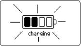
The battery symbol on the LCD indicates the remaining battery charge. The meter has a low battery warning, and when the symbol starts blinking, batteries should be charged or replaced with new ones. When the batteries are discharged the meter will automatically shut off to avoid erroneous readings.
5.1.1 Meter Battery Installation
Replace batteries in nonhazardous areas only.
Remove the 4 screws on the rear of the instrument and insert the batteries observing polarity.
If you wish to replace the supplied rechargeable batteries with
nonrechargeble alkaline batteries, move the switch in the bat-
tery compartment upward. A warning message is
displayed if you
connect the charging cable to a meter with alkaline batteries.
Nonrechargeable alkaline batteries can explode or leak if you try to charge them. Verify that the switch is in the up position when using
alkaline batteries to prevent recharging.
Note: Do not mix old and new alkaline batteries.
5.1.2 Charging Meter Batteries
Two cables are available for charging the HI 9829 batteries: HI 710045 and
HI 710046. AC power supply
In order to charge the rechargeable batteries, use the HI 710045 cable and the 12 Vdc power adapter.
• With the meter OFF, disconnect the probe.
25
•Connect the HI 710045 cable to the probe connector on the meter and power adapter, then connect the adapter to an AC power outlet.
•The battery charging animation will be displayed.
It takes about 6 hours to completely charge fully discharged batteries.
Note The meter log, GPS information, system setup and status can be viewed during battery charging. The battery charging status is indicated by a small animated battery icon found in the lower left corner.
During charging the meter may feel quite warm. This is normal. “Battery temp” (under “Meter Status”) may display values approaching 50 °C.
Automotive auxiliary power outlet (Cigarette lighter receptacle)
To charge batteries from a automotive auxiliary power outlet, use HI 710046 cable.
•Connect the HI 710046 cable to the probe connector on the meter and to the auxiliary plug.
•The battery charging animation will be displayed.
A complete battery charging will take about 6 hours if they are completely discharged.
26
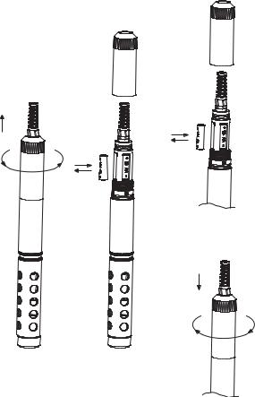
5.1.3 Probe Battery Installation (for logging probes only)
To install probe batteries:
Replace batteries in a nonhazardous area only. Remove the battery cover by turning it counterclockwise. Insert the batteries observing polarity.
Note: Do not mix old and new batteries.
Replace the battery cover by engaging the threads and turning it clockwise. Continue turning until it is flush with probe body.
27
5.2 METER INITIALIZATION
After connecting the desired sensors to the probe and connecting the probe to the meter (see previous chapter), turn the meter on by pressing ON/OFF.
After the initialization has been completed, the meter displays the PROBE STATUS SCREEN.
The probe status screen identifies the probe and attached sensors. Non-logging probes are identified as HI 7609829 and logging probes are identified as
HI 7629829.
Two active soft keys are found at the bottom of the status screen.
•Press <Measure> to access the measurement mode.
•Press <Param> to access the “Select Parameter” menu. (This screen can also be accessed from the main menu, see Chapter 6 for a detailed description.).
•Press the DOWN arrow to view additional information about the probe.
28

5.3 MEASUREMENT MODE
Measurement mode is one of the three main operating modes of HI 9829 (along with logging mode and setup mode).
During measurement mode HI 9829 will simultaneously measure data for all enabled parameters.
•Use the numbers on the keyboard to select the number of parameters that are shown on the screen at one time. The display will automatically resize the font.
•Press the [up] and [down] arrows to scroll through the enabled parameters if they do not fit on one screen.
Note A flashing measurement value indicates that the measurement is out of range.
A flashing measurement unit indicates that the user calibration has not been done and is needed for accurate readings.
•Press <Log> to enter the log menu. See Chapter 11 for details.
•Press <Menu> to enter the main setup menu. The main menu accesses the parameter setup, calibration, system setup, GPS and status options. See the following chapters for details.
29

5.4 SETUP MENU STRUCTURE
30
 Loading...