


Instruction Manual
HI 2221 HI 2223
pH/mV/ºC Bench Meters with Calibration Check
www.hannainst.com
1

Dear Customer,
Thank you for choosing a Hanna Instruments product.
Please read this instruction manual carefully before using these instruments.
This manual will provide you with the necessary information for correct use of these instruments, as well as a precise idea of their versatility.
If you need additional technical information, do not hesitate to e-mail us at tech@hannainst.com.
WARRANTY
HI 2221 and HI 2223 are guaranteed for two years against defects in workmanship and materials when used for their intended purpose and maintained according to instructions. The electrodes and the probes are guaranteed for a period of six months. This warranty is limited to repair or replacement free of charge.
Damage due to accidents, misuse, tampering or lack of prescribed maintenance are not covered.
If service is required, contact the dealer from whom you purchased the instrument. If under warranty, report the model number, date of purchase, serial number and the nature of the problem. If the repair is not covered by the warranty, you will be notified of the charges incurred. If the instrument is to be returned to Hanna Instruments, first obtain a Returned Goods Authorization number from the Technical Service department and then send it with shipping costs prepaid. When shipping any instrument, make sure it is properly packaged for complete protection.
TABLE OF CONTENTS |
|
WARRANTY ............................................................................................. |
2 |
PRELIMINARY EXAMINATION ...................................................................... |
3 |
GENERAL DESCRIPTION ............................................................................ |
3 |
FUNCTIONAL DESCRIPTION ........................................................................ |
4 |
HI 2221 SPECIFICATIONS ........................................................................ |
5 |
HI 2223 SPECIFICATIONS ........................................................................ |
6 |
OPERATIONAL GUIDE ................................................................................ |
7 |
pH CALIBRATION ...................................................................................... |
9 |
ENHANCED CALIBRATION MESSAGES ........................................................ |
14 |
ELECTRODE CONDITION & ELECTRODE RESPONSE TIME ............................ |
16 |
pH BUFFER TEMPERATURE DEPENDENCE ................................................. |
17 |
GOOD LABORATORY PRACTICE (GLP) ........................................................ |
18 |
LOGGING .............................................................................................. |
21 |
SETUP .................................................................................................. |
24 |
TEMPERATURE CALIBRATION (for technical personnel only) .......................... |
27 |
mV CALIBRATION (for technical personnel only) .......................................... |
29 |
PC INTERFACE ....................................................................................... |
30 |
ELECTRODE CONDITIONING & MAINTENANCE ............................................. |
34 |
TROUBLESHOOTING GUIDE ..................................................................... |
37 |
TEMPERATURE CORRELATION FOR pH SENSITIVE GLASS ............................. |
38 |
ACCESSORIES ........................................................................................ |
39 |
RECOMMENDATIONS FOR USERS ............................................................. |
43 |
2

PRELIMINARY EXAMINATION
Remove the instrument from the packing material and examine it carefully to make sure that no damage has occurred during shipping. If there is any damage, notify your Dealer or the nearest Hanna Customer Service Center.
Each instrument is supplied complete with:
•HI 1131P Glass-body Combination pH Electrode with 1 m (3.3 “) cable
•HI 7662 Temperature Probe
•HI 76404N Electrode Holder
•pH 4.01 & 7.01 Buffer Solutions (20 mL each)
•HI 7071 Electrolyte Solution
•12 VDC Power Adapter
•Instruction Manual
Note: Save all packing material until you are sure that the instrument functions correctly. All defective items must be returned in the original packing with the supplied accessories.
GENERAL DESCRIPTION
HI 2221 and HI 2223 are logging microprocessor-based pH/ORP/ temperature bench meters with Calibration Check.
Calibration Check performs a set of diagnostic tests during calibration using the history of electrode slope and offset to detect problems that can cause loss of accuracy.
Calibration Check Features are:
•Enhanced Calibration Messages
During calibration the user is warned if one or more parameters are not suitable to perform an accurate calibration.
•Electrode Condition on LCD Display
Determined from the electrode offset and slope.
•Electrode response time on LCD Display
Determined from electrode performance during calibration.
Other features include: up to five pH point calibration with seven memorized buffers (1.68, 4.01, 6.86, 7.01, 9.18, 10.01 and 12.45 pH), logging up to 100 samples (for HI 2221) and 500 samples (for HI 2223), GLP, calibration due alarm, pH reading with manual or automatic temperature compensation and PC software interface.
3

FUNCTIONAL DESCRIPTION
Front Panel
Rear Panel
1)Liquid Crystal Display (LCD).
2)CAL key, to enter and exit calibration mode.
3)CFM/GLP key, to confirm calibration, different values or to display Good Laboratory Practice information.
4) ºC key, to manually increase temperature value or other parameters.
5) ºC key, to manually decrease temperature value or other parameters.
6)SETUP key, to enter/exit SETUP mode.
7)RANGE key, to select measurement range, switch to focused data in SETUP or to toggle between buffer value and temperature during calibration.
8)LOG/CLR key, to store a value into memory, to clear pH calibration, or to delete log records.
9)RCL key, memory recall.
10)ON/OFF switch.
11)Power supply socket.
12)USB connector.
13)BNC electrode connector.
14)Temperature probe socket.
15)Electrode reference socket.
4
|
HI |
2221 |
|
SPECIFICATIONS |
|||
|
|
|
|
|
|
|
–2.00 to 16.00 pH |
|
|
|
|
Range |
|
|
±699.9 mV |
|
|
±2000 mV |
|
|
|
|
|
|
|
|
–20.0 to 120.0 °C |
|
|
|
|
|
|
|
0.01 pH |
|
|
|
|
Resolution |
|
|
0.1 mV (±699.9 mV) |
|
|
1 mV (±2000 mV) |
|
|
|
|
|
|
|
|
0.1 °C |
|
|
|
|
|
|
|
±0.01 pH |
|
|
|
|
Accuracy |
|
|
±0.2 mV (±699.9 mV) |
@ 20 °C/68 °F |
|
|
±1 mV (±2000 mV) |
|
|
|
±0.2 °C |
|
|
|
excluding probe error |
Calibration Check |
|
|
Yes |
|
|
|
|
Computer Interface |
|
|
Opto-isolated USB |
|
|
|
|
pH Calibration |
|
|
Up to 5 points, 7 buffers available |
|
(1.68, 4.01, 6.86, 7.01, 9.18, 10.01, 12.45) |
||
|
|
||
Logging |
|
|
100 points |
|
|
|
|
Temperature Compensation |
|
|
Manual or Automatic from: |
|
|
–20.0 to 120.0 °C (–4.0 to 248.0 °F) |
|
|
|
|
|
pH Electrode |
|
HI 1131P glass body, single junction refillable |
|
|
|
cell, BNC + pin (included) |
|
|
|
|
|
Temperature Probe |
|
|
HI 7662 stainless steel probe (included) |
|
|
|
|
Input Impedance |
|
|
1012 ohm |
Power Supply |
|
|
12 VDC adapter (included) |
|
|
|
|
Dimensions |
|
|
235 x 222 x 109 mm (9.2 x 8.7 x 4.3") |
|
|
|
|
Weight |
|
|
1.3 Kg (2.9 lb); |
|
|
kit with holder 2.1 Kg (4.6 lb) |
|
|
|
|
|
Environment |
|
|
0 – 50 °C (32 -– 122 °F) |
|
|
max RH 95 % non condensing |
|
|
|
|
|
Warranty |
|
|
2 years |
|
|
|
|
5
|
HI |
2223 |
|
SPECIFICATIONS |
|||
|
|
|
|
|
|
|
–2.00 to 16.00 pH |
|
|
|
–2.000 to 16.000 pH |
|
|
|
|
Range |
|
|
±999.9 mV |
|
|
±2000 mV |
|
|
|
|
|
|
|
|
|
|
|
|
–20.0 to 120.0 °C |
|
|
|
|
|
|
|
0.01 pH |
|
|
|
0.001 pH |
Resolution |
|
|
0.1 mV (±999.9 mV) |
|
|
1 mV (±2000 mV) |
|
|
|
|
|
|
|
|
0.1 °C |
|
|
|
|
|
|
|
±0.01 pH |
|
|
|
±0.002 pH |
Accuracy |
|
|
±0.2 mV (±999.9 mV) |
@ 20 °C/68 °F |
|
|
±1 mV (±2000 mV) |
|
|
|
|
|
|
|
±0.2 °C |
|
|
|
excluding probe error |
|
|
|
|
Calibration Check |
|
|
Yes |
|
|
|
|
Computer Interface |
|
|
Opto-Isolated USB |
|
|
|
|
pH Calibration |
|
|
Up to 5 points, 7 buffers available |
|
(1.68, 4.01, 6.86, 7.01, 9.18, 10.01, 12.45) |
||
|
|
||
Logging |
|
|
500 points |
|
|
|
|
Temperature Compensation |
|
|
Manual or Automatic from: |
|
|
–20.0 to 120.0 °C (–4.0 to 248.0 °F) |
|
|
|
|
|
pH Electrode |
|
|
HI 1131P glass body, single junction |
|
|
refillable cell, BNC + pin (included) |
|
|
|
|
|
Temperature Probe |
|
|
HI 7662 stainless steel probe (included) |
|
|
|
|
Input Impedance |
|
|
1012 ohm |
Power Supply |
|
|
12 VDC adapter |
|
|
|
|
Dimensions |
|
|
235 x 222 x 109 mm (9.2 x 8.7 x 4.3") |
|
|
|
|
Weight |
|
|
1.3 Kg (2.9 lb); |
|
|
kit with holder 2.1 Kg (4.6 lb) |
|
|
|
|
|
Environment |
|
|
0 – 50 °C (32 – 122 °F) |
|
|
max RH 95 % non condensing |
|
|
|
|
|
Warranty |
|
|
2 years |
|
|
|
|
6

OPERATIONAL GUIDE
POWER CONNECTION
Plug the 12 VDC adapter into the power supply socket.
Notes: • These instruments use non volatile memory to retain the pH, mV, temperature calibrations and all other settings, even when unplugged.
• Make sure a fuse protects the mains line.
ELECTRODE AND PROBE CONNECTIONS
For HANNA P Type pH or ORP electrodes (with internal reference) connect the electrode’s BNC to the socket on the back of the instrument and the pin to the reference socket.
Note: Electrode condition and response information is displayed on the bar graph gauges during the day the calibration is performed, only if HANNA P type (PIN) electrodes are used.
If the electrode is not recognized as a HANNA P type electrode, the bar graph gauges will blink (25 seconds OFF, 4 seconds ON, full bar graph).
For temperature measurement and automatic temperature compensation connect the temperature probe to the appropriate socket.
INSTRUMENT START-UP
•Turn the instrument on by pressing the ON/OFF switch located on the rear panel.
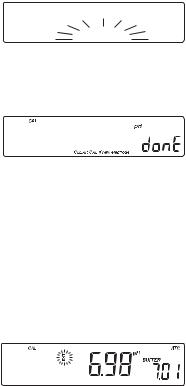
•All LCD tags are displayed and a beep is sounded while the instrument performs a self test.
•The instrument will display “LoAD” message and “ ” blinking until initialization is complete.
•The “Unscrew electrode refilling cap” message reminds the user to loosen or remove the electrode refilling cap to improve the electrode’s response time.
•The instrument automatically defaults to pH measurement mode unless a HANNA P type ORP electrode is detected.
pH MEASUREMENT
Make sure the instrument has been calibrated before taking pH measurements.
•Submerse the tip of a properly conditioned electrode (see page 34) and the temperature
3 cm (1¼")
7
probe approximately 3 cm (1¼”) into the sample to be tested and stir gently. Allow time for the electrode to stabilize.
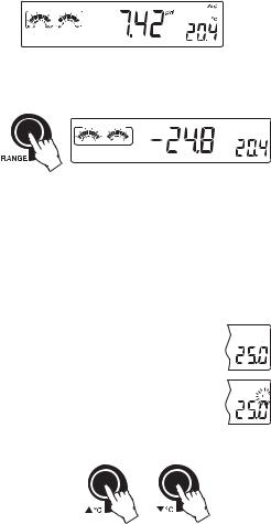
•The pH is displayed on the primary LCD and the temperature on the secondary LCD.
•The pH reading is out of range, the closest full-scale value will be displayed blinking on the primary LCD.
•It is also possible to view the mV reading by pressing the RANGE key.
mV |
C |
POOR |
GOOD SLOW |
FAST |
If measurements are taken successively in different samples, it is recommended to rinse the electrode thoroughly with deionized water or tap water and then with some of the next sample to prevent cross-contamination.
The pH reading is affected by temperature. In order to measure the pH accurately, this temperature effect must be compensated for. To use the Automatic Temperature Compensation feature, connect and submerse the HI 7662 temperature probe into the sample as close to the electrode
as possible and wait for a few minutes. |
ATC |
If the temperature of the sample is known, manual compensation can be performed by disconnecting the temperature probe.
The display will show the last recorded temperature reading with the “°C” symbol blinking.
C
MTC
C 
The temperature can now be adjusted with the ARROW keys (from -20.0 ºC to 120.0 ºC).
ORP MEASUREMENTS
An optional ORP electrode must be used to perform ORP measurements (see Accessories).
Oxidation-Reduction Potential (REDOX) measurements provide the quantification of the oxidizing or reducing power of the tested sample.
The surface of the ORP electrode must be clean and smooth in order to obtain an accurate measurement.
8

Pretreatment solutions are available to condition the electrode and speed up the response time.
•The instrument automatically defaults to the mV measurement mode if HANNA P type ORP electrode is detected.
3 cm |
(1¼") |
•Submerse the ORP electrode tip (3 cm/1¼”) into the sample. Allow a few minutes for the reading to stabilize.
•The instrument displays the mV reading on the primary LCD.
•If the reading is out of range, the closest full-scale value will be displayed blinking on the primary LCD.
TAKING TEMPERATURE MEASUREMENTS
Connect the HI 7662 temperature probe and turn the instrument on. Dip the temperature probe into the sample and allow the reading on the secondary LCD to stabilize.
pH CALIBRATION
Calibrate the instrument frequently, especially if high accuracy is required. For best results and constant display of electrode condition and electrode response on the bar graph gauges, daily calibration is recommended.
The instrument should be recalibrated:
•Whenever the pH electrode is replaced.
•At least once a day.
•After testing aggressive chemicals.
•If high accuracy is required.
•If “CAL DUE” message is displayed during measurement.
Every time you calibrate the instrument use fresh buffers and perform an electrode cleaning procedure (see page 36).
PREPARATION
Pour small quantities of the buffer solutions into clean beakers. If possible, use plastic or glass beakers to minimize any EMC interferences.
For accurate calibration and to minimize cross-contamination, use two beakers for each buffer solution. One for rinsing the electrode and one for calibration.
9
PROCEDURE
Calibration can be performed at up to five points. For accurate measurements a three point calibration is recommended. Calibration can be performed using the seven memorized buffers:
• pH 1.68, 4.01, 6.86, 7.01, 9.18, 10.01 and 12.45.
FIVE-POINT CALIBRATION
For most applications it is recommended that pH 7.01 or 6.86 buffers be used as the first calibration point and pH 4.01 (for acidic samples) or pH 9.18/10.01 (for alkaline samples) as the second calibration point.
Note: The pH 12.45 buffer is not for general measurement; use only if the sample is very alkaline to avoid sodium error.
•Submerse the pH electrode and the temperature probe approximately 3 cm (1¼”) into a buffer solution and stir gently. The temperature probe should be close to the pH electrode.
•Press the CAL key. “CAL” and “pH” tags will be on, and the “CLEAR CAL if new electrode” tag will blink.
CAL
pH
CLEAR CAL if new electrode
•Press the CLR key if you are using a new electrode or want to clear the calibration history. The instrument will display the “donE” message for a few seconds.
•Press the CAL key, or wait a few seconds to continue.
It is very important to clear the calibration history when a new electrode is used because all error and warning messages that appear during calibration depend on the calibration history.
Note: • The “CLEAR CAL if new electrode” will only appear if the instrument has been previously calibrated.
•The “CAL”, “pH” and “BUFFER” tags will appear and the “7.01” buffer will be displayed on the secondary LCD.
•If necessary, press the ARROW keys to select a different buffer value.
•The “ ” tag will blink until the reading has stabilized.
10
•When the reading is stable and close to the selected buffer, the “CFM” tag will blink and if enabled, an audible signal will sound.
•Press the CFM key to confirm the calibration. The calibrated value will be displayed on the primary LCD and the second expected buffer value on the secondary LCD.
•After the first calibration point is confirmed, submerse the pH electrode and the temperature probe approximately 3 cm (1¼”) into the second buffer solution and stir gently. The temperature probe should be close to the pH electrode.
•If necessary, press the ARROW keys to select a different buffer value.
Note: The instrument will automatically skip the buffer used for the first point. It also skips 6.86 if 7.01 was used, and vice versa. Likewise, it will skip 9.18 if 10.01 has been used, and vice versa.
•The “ ” tag will blink on the LCD until the reading is stable.
•When the reading is stable and close to the selected buffer the “CFM” tag will blink.
•Press CFM to confirm calibration.
•The calibrated value is then displayed on the
primary LCD and and the third expected buffer value on the secondary LCD.
•After the second calibration point is confirmed, submerse the pH electrode and the temperature probe approximately 3 cm (1¼”) into the next buffer solution and stir gently. The temperature probe should be close to the pH electrode.
•If necessary, press the ARROW keys to select a different buffer value.
•The “ ” tag will blink on the LCD until the reading is stable.
•When the reading is stable and close to the selected buffer the “CFM” tag will blink.
• Press CFM to confirm calibration.
11

•After the third calibration point is confirmed, submerse the pH electrode and the temperature probe approximately 3 cm (1¼”) into the next buffer solution and stir gently. The temperature probe should be close to the pH electrode.
•If necessary, press the ARROW keys to select a different buffer value.
•The “ ” tag will blink on the LCD until the reading is stable.
•When the reading is stable and close to the selected buffer the “CFM” tag will blink.
•Press CFM to confirm calibration.
• After the fourth calibration point is confirmed, submerse the pH electrode and the temperature probe approximately 3 cm (1¼”) into the next
buffer solution and stir gently. The temperature probe should be close to the pH electrode.
•If necessary, press the ARROW keys to select a different buffer value.
•The “ ” tag will blink on the LCD until the reading is stable.
•When the reading is stable and close to the selected buffer the “CFM” tag will blink.
•Press CFM to confirm calibration.
• The instrument stores the calibration value and returns to normal measurement mode.
FOUR, THREE OR TWO-POINT CALIBRATION
•Proceed as described in “FIVE-POINT CALIBRATION” section.
•Press CAL after the fourth, third or second calibration point was confirmed. The instrument will memorize the calibration data and return to measurement mode.
ONE-POINT CALIBRATION
Two SETUP selectable options are available: “Pnt” and “OFFS”.
If the “Pnt” option is selected, the new calibration point overrides an existing one. The adjacent slopes will be reevaluated.
If the “OFFS” option is selected, an electrode offset correction is performed. The adjacent slopes will remain unchanged.
•Proceed as described in “FOUR, THREE or TWO-POINT CALIBRATION” section.
•Press CAL after the first calibration point was confirmed. The instrument will memorize the one-point calibration data and return to measurement mode.
12

Notes: • To clear calibration parameters for all uncalibrated buffers starting with current buffer, press CLR. The calibration will continue from the current point. If this procedure is performed while calibrating in the first calibration point, the instrument returns to measurement mode.
•Press RANGE to toggle between pH buffer, calibration buffer number and
temperature reading.
13

ENHANCED CALIBRATION MESSAGES
The stored calibration history to used issue error and warning messages during calibration to help ensure the highest accuracy.
As electrode aging is normally a slow process, substantial changes from previous calibrations are likely due to a temporary problem with the electrode or buffers.
ERROR MESSAGES
Error messages appear if one or all of the calibration parameters are out of accepted windows. Calibration can not continue when these errors are displayed.
WRONG BUFFER
This message appears when the difference between the pH reading and the value of the selected buffer is too big. If this error message is displayed, check if you have selected the proper calibration buffer.
CLEAN ELECTRODE
This error message indicates a bad electrode condition (offset out of accepted window, or slope under the accepted lower limit).
Clean the electrode according to the Cleaning Procedure on page 36 to improve its condition and repeat the calibration. This ensures the removal of film, dirt or deposits on the glass bulb and reference junction.
CHECK ELECTRODE alternating with CHECK BUFFER
This error message appears when electrode slope exceeds the highest accepted slope limit. You should check your electrode and use fresh buffer.
ELECTRODE
This message appears if the cleaning procedure performed as a result of the above two messages is found by the instrument to be unsuccessful.
14
 Loading...