


Instruction Manual
C 114
Multiparameter
Turbidity &
Free and Total Chlorine
This Instrument is in Compliance with the CE Directives
w w w . h a n n a i n s t . c o m

Dear Customer,
Thank you for choosing a Hanna Product.
Please read this instruction manual carefully before using the instrument.
This manual will provide you with the necessary information for the correct use of the instrument, as well as a precise idea of its versatility. If you need more technical information, do not hesitate to e-mail us at tech@hannainst.com.
This instrument is in compliance with
 directives EN 50081-1 and EN 50082-1.
TABLE OF CONTENTS |
|
Preliminary Examination ............................. |
3 |
General Description .................................... |
4 |
Principle of Operation ................................. |
6 |
Functional Description ................................ |
9 |
Specifications ........................................... |
12 |
Operational Guide ..................................... |
13 |
Calibration ................................................ |
19 |
Diagnostic mode ....................................... |
27 |
Logging with C 114 ................................... |
28 |
User-selectable Shutdown ......................... |
30 |
Battery Replacement ................................. |
31 |
Diagnostic Codes ..................................... |
32 |
Accessories .............................................. |
33 |
Warranty ................................................... |
34 |
CE Declaration of Conformity ................... |
35 |
ISO 9000 Certified
Company since 1992
PRELIMINARY EXAMINATION
Remove the instrument from the packing material and examine it to make sure that no damage has occurred during shipping. If there is any damage, notify your Dealer.
C114 is supplied complete with:
•1.5V AA Size Batteries (4 ea.)
•Glass Cuvet
•Cap
In addition to the above items, an optional starter kit HI 731327 is available, supplied with:
•Measurement cuvets (2 pcs)
•Primary calibration standards:
HI 93102-0 AMCO-AEPA-1 0 NTU* calibration solution, 30 mL
HI 93102-20 AMCO-AEPA-1 20 NTU* calibration solution, 30 mL
•HI 93703-50 Cleaning solution, 230 mL
•HI 731318 Tissue for wiping the cuvets (4 pcs)
•HI 710031 Rugged carrying case
Note: Save all packing material until you are sure that the instrument functions correctly. Any defective item must be returned in its original packaging with the supplied accessories.
*1 NTU (Nephelometric Turbidity Unit) = 1 FTU (Formazine Turbidity Unit)
2 |
3 |

GENERAL DESCRIPTION
The Hanna C114 is a portable microprocessor driven, multiparameter instrument. The meter measures Free & Total Chlorine and Turbidity.
In the colorimetric mode, the user can select either factory preprogrammed calibration settings or calibrate the meter using customized calibration values based on the concentration or relative absorbance of the sample. Calibration data is also stored in a non-volatile EEPROM.
In the turbidity mode, periodic recalibration of the meter with primary standards according to regulatory requirements or personal experience is suggested. Turbidity ranges are 0.00- 9.99 NTU and 10.0-50.0 NTU.
C114 complies with G.L.P. Standards (Good Laboratory Practice), that is:
•When switched on, the LCD displays all segments (display check).
•Battery status is monitored during every measurement cycle warning the user if the batteries become weak. In addition, C102 will turn itself off before low voltage causes erroneous readings.
•It utilizes a real time clock and recalls calibration data such as date, time and calibration values.
To facilitate field tests, the meter provides a logging mode. In this mode, the user can store up to twenty five time-tagged measurements in RAM and scroll the memory at any time.
There are eight keys for the different operational modes. The large Liquid Crystal Display is dual-level: the upper level has four
digits and can display the measured parameter in hundredths. The lower level has three characters and indicates current mode (e.g. F CL for free chlorine or TR for turbidity). Different LCD segments indicate low battery, logging mode, date, time, etc.
A pure Green LED has been utilized as a light source for both turbidimetric and colorimetric measurements. A silicon photocell is used to receive transmitted light from colorimetric channel while another photocell receives scattered light from the turbidimetric (nephelometric) channel.
In order to measure chlorine parameters, all the operator has to do is zero the blank sample and then add 1 packet of reagent. After placing the cuvet back in the meter and pressing READ, the measurements are shown directly on the LCD.
The instrument operates with four AA batteries and may be operator-programmed to turn itself off automatically after 10, 20, 30, 40, 50 or 60 minutes of inactivity.
C 114 and all accessories such as sample vials, reagent pillows, primary standards, can be easily stored in the optional carrying case (HI 710031).
4 |
5 |
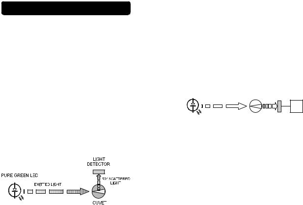
PRINCIPLE OF OPERATION
Turbidity Mode
C 114 has been designed to perform measurements according to the USEPA’s 180.1 method and the Standard Method 2130B.
The instrument functions by passing a beam of light through a vial containing the sample being measured.
The light source is a Pure Green LED to ensure that any interference caused by a colored samples is minimized.
A sensor, positioned at 90° with respect to the direction of light, detects the amount of light scattered by the undissolved particles present in the sample. The microprocessor converts such readings into NTU* values.
NTU units are equal to FTU units. However, there are other known measurement units for turbidity, namely the Jackson Turbidity Unit (JTU) based on the old method of Jackson's candle, and Silica Unit (mg /L of SiO2). The conversion table between these measurement units is shown below:
|
JTU |
NTU/FTU |
SiO2 (mg/ L) |
|
|
|
|
JTU |
1 |
19 |
2.5 |
|
|
|
|
NTU/FTU |
0.053 |
1 |
0.13 |
|
|
|
|
SiO2 (mg/ L) |
0.4 |
7.5 |
1 |
|
|
|
|
* 1 NTU = 1 FTU
6
Colorimetric Mode
The color of every object we see is determined by a process of absorption and emission of the electromagnetic radiation (light) of its molecules.
Colorimetric analysis is based on the principle that specific compounds react with others to form a color, the intensity of which is proportional to the concentration of the substance being measured.
LED |
LIGHT |
EMITTED LIGHT |
DETECTOR |
|
|
CUVET |
MICROPROCESSOR |
Block diagram of an ion specific measurement
When a substance is exposed to a beam of light intensity Io, a portion of the radiation is absorbed by the substance's molecules and a radiation of intensity I, lower than Io, is emitted.
The quantity of radiation absorbed is given by the Lambert-Beer Law:
log Io/I = ε λ c d
Where log Io/I = Absorbance (A)
ε λ = molar extinction coefficient of the substance at wavelength λ
c = molar concentration of the substance
d = optical distance light travels through the sample
Since other factors are known, the concentration "c" can be calculated from the color intensity of the substance determined by the emitted radiation I.
An LED (Light Emitting Diode) emits radiation at a relatively narrow spectrum, supplying the system with the intensity Io.
7
A substance absorbs a color complimentary to the color it emits. For example, a substance appears yellow because it absorbs blue light. As a result, the Hanna meters use LED’s with specific wavelengths to measure samples.
The optical distance (d) is measured by the internal diameter of the cuvet containing the sample.
The photoelectric cell collects the radiation I that is not absorbed by the sample and converts it into an electric current.
The microprocessor converts the value into the desired measuring unit and displays it on the LCD.
The measurement process is done in two phases: setting the meter to zero and actual measurement.
The cuvet is an optical element and hence has an important role in the measurement process. Both the measurement and the calibration cuvets must be optically identical to provide the same measurement conditions.
It is also important that the surface of the cuvet is clean and free from scratches or dents, in order to avoid measurement interference due to unwanted reflection and absorption of light.
It is recommended that wherever possible the cuvet walls are not touched by the operator.
Furthermore, in order to maintain the same conditions during the zeroing and the measuring phases, it is necessary to close the cuvets to prevent any contamination.
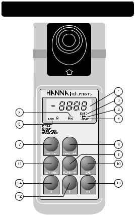
FUNCTIONAL DESCRIPTION
1)Primary
LCD: The four-digit LCD shows all segments for several seconds when the meter is switched on. It then displays four dashes to indicate “ready to measure”. It is also the area where the date, time and value of last calibration are shown. In “Read” and “Zero” mode, “SIP” is shown to indicate “Sample In Progress”. The upper level also indicates the concentration or turbidity of the sample, as well as differ-
8 |
9 |

ent diagnostic modes, such as “-BA-” for low battery.
2)Secondary
LCD: The three-digit LCD shows the current mode of measurement
that is “F CL”, “t CL”, “tr”, and diagnostic or calibration modes, such as “d 11” , “2 Fn”, “5 c1”.
3) DATE: Indicates that the upper level of LCD is showing the current date, the date of last calibration or the date of logged measurement in memory.
4) TIME: Indicates that the upper level of LCD is showing the current time, the time of last calibration or the time of logged measurement in memory.
5) LOBAT: Blinking segment warns user of low battery voltage.
6) LOG: If intermittent, it indicates that the user is in the scroll mode viewing the logged measurements. If fixed, it indicates that the meter is in the log mode and every reading taken will be stored in memory.
7)ON/OFF key:Turns the meter on and off.
8)ZERO /  key: In ion specific (colorimet-
ric) mode, it zeros the sample. In calibration and diagnostic modes, it functions as ENTER (not used in turbidity mode).
9) READ /  key: Takes the measurement of concentration/turbidity of the
sample which is shown on the LCD. In diagnostic or calibration mode, shifts the flashing digit to the right.
10) CAL key: If pressed during calibration, the calibration procedure will be aborted and the last calibration data will be reinstated. If pressed together with the ALT key for less then 3 seconds, the diagnostic mode will be entered. If pressed together with the ALT key again, the meter will quit diagnostic mode. If pressed for more then 3 seconds, an intermittent “CAL” prompt will appear on the upper LCD level and the calibration procedure is entered.
11) GLP/Abs key: In ion specific mode, it will toggle concentration/absorbance readings on the upper LCD. In turbidity mode, date, time and the two calibration values of the current mode will be shown. If pressed in time/date setup mode, the meter will quit current mode without making any changes to current time/date.
12) key |
Scrolls upwards through the |
|
parameters to be measured. |
|
In calibration/diagnostic |
|
mode, increments the blink- |
|
ing digit by one. If pressed |
|
together with ALT while the |
|
meter is in logging mode, the |
|
upper LCD will show the data |
|
(date/time/value) in the |
10 |
11 |
 Loading...