


Instruction Manual
PCA 311, PCA 321, PCA 331
Bromine, pH, Temperature, ORP
Analyzers
www.hannainst.com
1

Dear Customer,
Thank you for choosing a Hanna Product.
This instruction manual has been written for the following: PCA 331 – Bromine, pH, temperature, ORP analyzer. PCA 321 – Bromine, pH, temperature analyzer.
PCA 311 – Bromine analyzer.
The analyzers have features such as: automatic bromine measurement, pH, temperature and ORP measurement, bromine and pH dosing regulator, selectable sampling periods, alarm system, data link through GSM network, user friendly interface, serial communication through RS485, recorder output, 4-20mA dosing output, Nema 4X enclosure.
The ordering code for bromine analyzers is:
PCA 3a1-b
a = 1 - Bromine analyzer
2 - Bromine, pH and Temperature analyzer
3 - Bromine, pH, Temperature and ORP analyzer
b = 1 - 115V AC 50-60Hz
2 - 220V AC 50-60Hz
Please read this instruction manual carefully before using the instrument. It will provide you the necessary information for the correct use of the instrument, as well as a more precise idea of its versatility.
Hanna Instruments reserves the right to modify the design, construction and appearance of its products without advance notice.
2

TABLE OF CONTENTS
PRELIMINARY EXAMINATION........................................ |
6 |
GENERAL DESCRIPTION.............................................. |
7 |
MECHANICAL DIMENSIONS........................................ |
9 |
FUNCTIONAL DESCRIPTION........................................ |
10 |
DISPLAY, LEDS AND KEYBOARD................................... |
11 |
SPECIFICATIONS....................................................... |
14 |
OPERATING DESCRIPTION......................................... |
16 |
Bromine measurement ...................................... |
16 |
Method of analysis ........................................ |
17 |
pH and temperature measurement ................... |
17 |
ORP measurement ........................................ |
17 |
INITIAL PREPARATION AND INSTALLATION................... |
18 |
Installation Personnel...................................... |
18 |
Location of the Instrument............................... |
18 |
Hydraulic Connections.................................... |
18 |
Installing the Input Filter................................... |
19 |
Installing the pH and ORP probes ..................... |
20 |
Installing the Pump Tubes................................. |
21 |
Electrical Connections..................................... |
22 |
STARTUP..................................................................... |
26 |
USER INTERFACE ....................................................... |
27 |
Panels organization ........................................ |
27 |
Main panels ............................................... |
27 |
Measure panels ............................................. |
28 |
Messages .................................................... |
29 |
Menu mode ................................................ |
29 |
Password procedure ..................................... |
29 |
Navigating through menu .............................. |
30 |
Modify a parameter ........................................ |
30 |
PROGRAMMING THE ANALYZER .............................. |
32 |
GENERAL SETTINGS ............................................... |
33 |
3
Changing the password ................................. |
33 |
Setting the language ..................................... |
33 |
Analyzer serial number and software version ...... |
33 |
Time and date ............................................. |
33 |
WORKING MODE ................................................... |
34 |
Automatic mode .......................................... |
34 |
Standby mode ............................................. |
34 |
Manual mode ............................................. |
34 |
Read on demand ........................................... |
35 |
Direct read ................................................. |
35 |
System error relay.............................................. |
35 |
BROMINE SETTINGS ............................................... |
36 |
Reagent changing .......................................... |
36 |
Measure settings .......................................... |
37 |
Measure info ................................................ |
37 |
Analog output ............................................. |
37 |
Bromine dosing ........................................... |
38 |
Alarms ........................................................ |
39 |
CALIBRATE THE MEASURING CELL ............................. |
40 |
Calibration date and factor ............................ |
40 |
Calibration procedure ..................................... |
40 |
pH SETTINGS (PCA 321, PCA 331) ............................. |
41 |
Measure info............................................... |
41 |
Analog output ............................................. |
42 |
pH dosing .................................................. |
42 |
Alarms ....................................................... |
44 |
pH CALIBRATION (PCA 321, PCA 331) ....................... |
44 |
One point calibration ................................... |
45 |
Two-points calibration ..................................... |
46 |
Process pH calibration .................................... |
46 |
Set default calibration ..................................... |
47 |
TEMPERATURE SETTINGS (PCA 321, PCA 331) ............ |
48 |
Units ......................................................... |
48 |
Measure info .............................................. |
48 |
4
Analog output............................................. |
48 |
Alarms ....................................................... |
49 |
ORP SETTINGS (PCA 331) .......................................... |
50 |
Measure info .............................................. |
50 |
Analog output ............................................ |
50 |
Alarms ....................................................... |
51 |
ANALOG OUTPUT .................................................. |
52 |
Select the analog output type .......................... |
52 |
Dosing through 4-20 mA output ...................... |
52 |
CALIBRATE THE ANALOG OUTPUT ............................. |
53 |
Output middle range ........................................ |
54 |
SYSTEM LOG .......................................................... |
55 |
Set log ....................................................... |
55 |
Clear system log .......................................... |
55 |
View log ..................................................... |
55 |
SERIAL COMMUNICATION ........................................ |
57 |
Standard mode ............................................ |
57 |
GSM ..................................................................... |
58 |
GSM mode ................................................ |
58 |
Setting the GSM feature ................................. |
58 |
GSM connection .......................................... |
59 |
Setting SMS feature ......................................... |
60 |
Modem connection.......................................... |
64 |
MAINTENANCE ...................................................... |
65 |
Electrode conditioning and maintenance ........... |
66 |
Changing peristaltic pump tubing .................... |
68 |
Tubing replacement.......................................... |
69 |
Cleaning measurement cell .............................. |
69 |
Cell Cleaning Procedure ................................ |
70 |
ERRORS, ALARMS AND WARNINGS ............................ |
71 |
ACCESORIES ........................................................... |
74 |
5

PRELIMINARY EXAMINATION
Remove the analyzer from the packing material and examine it carefully to make sure that no damage has occurred during shipping. If there is any noticeable damage, notify your dealer immediately.
Each analyzer is supplied complete with:
•2 reagent bottles (1 indicator and 1 buffer solution)
•2 reagent bottle caps
•1 DPD compound powder
•tubing
Note: Save all packing materials until you are sure that the instrument functions correctly. Any damaged or defective items must be returned in their original packing materials together with the supplied accessories.
WARNING: The PCA 311 - PCA 331 series of Bromine, pH and ORP Analyzers are not designed for use with samples that are inflammable or explosive in nature. If any sample solution other than water is used with these products, test the sample/ product compatibility to assure user safety and proper product performance.
Safety Precautions: Please take the time to read the safety precautions carefully wherever they appear in this manual. They are provided to prevent personal injury and damage to the instrument. This safety information applies to the operators and service personnel and the following two captions are used:
CAUTION: identifies conditions or practices that could result in damage to the instrument or persons;
Warning: identifies conditions or practices that could result in personal injury or loss of life.
Note: Because of the inherent dangers in handling chemical samples, standards and reagents, HANNA Instruments strongly recommends the users of this product to review the Material Safety Data Sheets and become familiar with safe handling procedures and proper usage prior to handling any chemicals.
6

GENERAL DESCRIPTION
The Hanna PCA 311, PCA 321 and PCA 331 series of bromine, pH, ORP and temperature analyzers are microprocessor controlled, process analyzers which continuously monitor a sample stream for bromine content, pH, ORP and temperature values.
The PCA 311-331 monitor the bromine in the 0.0 to 10.0 mg/L range depending on the factory settings and used reagents.
In the DPD Colorimetric method, N, N-Diethyl-p-phenylene- diamine indicator and a buffer are mixed with the sample.
The resulting chemical reaction causes a magenta color to form. The color intensity is proportional to the concentration of bromine. The color intensity is measured photometrically (with a light beam and a photodetector) and converted to bromine concentration, in mg/L, which is displayed on the front panel.
Indicator and buffer reagent bottles are placed directly into the instrument case. With a sampling period of 5 minutes, reagents need to be replenished about once a month. The reagent bottles are easily visible through the transparent window allowing the operator to check the reagent levels.
PCA 321 and PCA 331 analyzers use a HI 1005 probe to continuously measure the pH of the sample stream in the range of 0 to 14 pH. The sample temperature is measured in the 5 to 75°C range. pH and temperature are displayed on the front panel. pH value is corrected with temperature.
PCA 331 analyzer use HI 2008 platinum ORP electrode to continuously measure the sample ORP value.
The pH/temperature combined sensor and the ORP sensor are placed inside the case, directly in the sample stream.
The case of PCA 311-331 analyzers meet NEMA 4X, 12 and
7
13 standards. Molded fiberglass polyester has outstanding chemical and temperature resistance.
The case provides wall mounting capability and door gasket assures a watertight and dust-tight seal.
The electrical and hydraulic connections are made through the side of the enclosure.
The front cover is secured with two lockable latches.
Four bromine level setpoints can be adjusted by the operator: a proportional dosing setpoint, two alarm setpoints and a minimum level for dosing.
The proportional dosing factor (1/delta) is user selectable with a delta between 0.2 and 10.0 mg/L (ppm). Bromine dosing system controls a SPST relay.
Each bromine alarm can be enabled or disabled.
Three pH level setpoints can be adjusted by the operator: a dosing setpoint and two alarm setpoints. The pH control mode is user selectable: on/off or proportional dosing.
The proportional dosing factor (1/delta) is user selectable with a delta between 0.1 and 2 pH . The on/off dosing hysteresis is user selectable between 0.05 and 2.00 pH. pH dosing system controls a SPST relay.
Each pH alarm can be enabled or disabled.
For temperature and ORP, two alarm levels can be set by the user.
Each temperature or ORP alarm can be enabled or disabled. Alarm condition controls a SPDT relay.
A system error feature provides relay activation to signals need for operator intervention.
System error condition controls a SPST relay.
Voltage output ranges of 0-10mV, 0-100mV, 0-1V or a current output of 4-20 or 0-20 mA are available to drive an external device such as a chart recorder.
The analyzer can drive a proportional dosing pump through the 4-20 mA output, for bromine or for acid/alkali dosing.
The analog output is fully programmable and could be proportional with bromine concentration, pH, ORP or temperature value. The limits of the analog output is selectable for each parameter.
8
The analyzer can store up to 3500 readings (at least 7 days at 3 minutes sampling interval), that are available for consulting or downloading.
The PCA 311-331 analyzers can be monitored or controlled through RS485 or GSM network connection.
Errors, alarms and warnings are sent through SMS (using GSM module HI 504900).
The analyzer state can be interrogated by a simple call using GSM phone.
Time is displayed on the main panel and a time related warning system for “Old calibration” “Reagent expired” and “SIM expired” is available.
The language for user interface can be easily changed without restarting the analyzer.
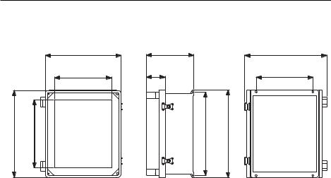
MECHANICAL DIMENSIONS
FRONT VIEW |
SIDE VIEW |
REAR VIEW |
338.3 |
209.8 |
367.1 |
13.32" |
8.26" |
14.45" |
254 |
83.1 |
254 |
10" |
3.27" |
10" |
389.1 |
15.32" |
304.8 |
12" |
374.8 |
14.76" |
393.7 |
15.5" |
Case dimensions in mm & inches
9

FUNCTIONAL DESCRIPTION
|
|
|
|
|
|
|
|
|
|
|
|
|
|
|
|
|
|
|
|
|
|
|
|
|
|
|
|
|
|
|
|
|
|
|
|
|
|
|
|
|
|
|
|
|
|
|
|
|
|
|
|
|
|
|
|
|
|
|
|
|
|
|
|
|
|
|
|
|
|
|
|
|
|
|
|
|
|
|
|
|
|
|
|
|
|
|
|
|
|
|
|
|
|
|
|
1. Alarms, dosing, system error LED’s |
13. Buffer Bottle |
||||||||||
2. |
Character Display |
14. Pressure Regulator Output Port |
|||||||||
3. |
Cable glands |
15. Incoming Pressure Regulator |
|||||||||
4. |
Keypad |
16. Indicator Bottle |
|||||||||
5. |
Peristaltic Pump |
17. Sample Inlet Port |
|||||||||
6. |
Access Point to Cell |
18. pH Electrode (not included) |
|||||||||
7. |
Measuring Cell |
19. Electrodes Holder |
|||||||||
8. |
Drain Tube |
20. Sample Output Port |
|||||||||
9. |
Output Port |
21. Electrovalve |
|||||||||
10. Drain Port Valve |
22. ORP Electrode (not included) |
||||||||||
11. Drain Port of Measuring Cell |
23. Reagent Tubing |
||||||||||
12. Sample Tubing |
24. Line Input |
||||||||||
1 0
DISPLAY, LEDS AND KEYBOARD
DISPLAY
The display contains 4 lines with 20 characters on one line. The information and error messages are clearly displayed in plain language, without error codes.
The display has backlight for better visibility.
The analyzer is in main panels mode when displays a panel that contains the measured values. Several main panels could be selected by pressing the up and down arrow keys. The PCA 311 do not have the main mode for the display.
1 - measured values
2 - controller status
3 - current time and date
4 - message line
The display is in bromine, pH, ORP or temperature measuring panels mode when displays one of those values and secondary information related to it. Several panels with different secondary information could be selected by pressing the up or down arrow keys.
When the display is in one of the above modes, the measuring units, the current time and the alarm or error status are also displayed. PCA 311 is always in bromine measuring panels.
1 1
1 2 3
|
16:35 |
|
|
1.3 mg/L Alarm |
|
5 |
<Br Calibration Old> |
4 |
|
Min:0.0 Max:5.6 |
|
|
|
|
|
|
|
1 - measured value (bromine, pH, ORP or temperature) 2 - measurement units (mg/L, pH, mV, °C or °F)
3 - current time in format HH:MM
4 - warnings, alarms and errors, displayed one at a time 5 - secondary information.
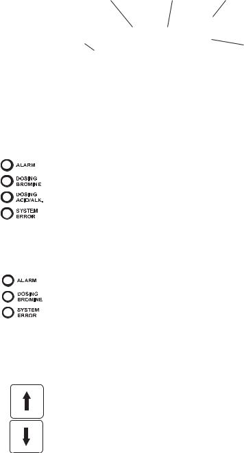
LEDs
Three or four LEDs are present on the front panel:
ALARM LED (red), signals the presence of at least one alarm and the closing of the Alarm relay. When the alarm is present, the LED blinks. When the analyzer is in
MANUAL mode, the LED is on but not blinking.
DOSING BROMINE LED (green), signals the closing of the bromine dosing relay. When dosing stops, the LED is turned off.
DOSING ACID/ALK. LED (green), signals the closing of the acid/alkali dosing relay. When dosing stops, the LED is turned off (PCA 321 and PCA 331 only).
SYSTEM ERROR LED (red), signals the presence of an error
and the closing of the System error relay. When the
error is present, the LED blinks. When in STANDBY
mode, the led is on but not blinking.
For PCA 311 the system error LED is moved in the dosing ACID/ALK. LED position.
KEYPAD
The keypad has 8 keys with the following signification:
UP and DOWN ARROWS
•select the main display appearance,
•select the menu,
•select an item from a list,
•edit values.
1 2

|
LEFT and RIGHT ARROWS |
|
|
• |
select an error message, |
|
• |
select an item to edit or |
|
• |
select the current digit for editing. |
MENU |
MENU enter in menu mode. |
|
CFM |
CFM confirm the selected menu and edited values. |
|
|
||
SET |
SET starts editing the selected item. |
|
|
ESC |
|
ESC |
• |
return to the previous menu, |
|
• |
exit from operation without saving. |
1 3

SPECIFICATIONS
BROMIN E MEASUREMEN T AN D DOSIN G (All models)
Range |
0.0 to 10.0 mg/L |
|
|
Resolution |
0.1 mg/L |
|
|
Accuracy |
± 8% or ± 0.1 mg/L whichever is greater |
|
|
Typical EMC deviation |
± 0.1 mg/L |
|
|
Calibration |
1 point |
|
|
Minimum detectable level 0.1mg/L |
|
|
|
Sampling rate |
3 to 90 minutes |
|
|
Dosage |
Proportional relay or 4-20mA output |
|
|
Delta |
selectable 0.2 to 4.0 mg/L |
|
|
pH MEASUREMEN T AN D DOSIN G (PCA 321 and PCA 331) |
|
|
|
Range |
0.00 to 14.00 pH |
|
|
Resolution |
0.01 pH |
|
|
Accuracy |
± 0.05 pH |
|
|
Typical EMC deviation |
± 0.2 pH |
|
|
Calibration |
1; 2 points or in line calibration |
|
|
Dosing rate |
3 to 120 seconds |
|
|
Dosage |
On/Off or proportional, relay or 4-20mA output |
|
|
Delta |
selectable 0.1 to 2 pH |
|
|
Hysteresis |
selectable 0.05 to 2 pH |
|
|
ORP MEASUREMEN T (PCA 331) |
|
|
|
Range |
0 to 2000 mV |
|
|
Resolution |
1 mV |
|
|
Accuracy |
± 1 mV |
|
|
Typical EMC deviation |
± 10 mV |
1 4

TEMPERATURE MEASUREMEN T (PCA 321 and PCA 331)
Range |
5.0 to 75.0 °C (41 to 167 °F) |
|
|
Resolution |
0.1 °C |
|
|
Accuracy |
± 0.5 °C |
|
|
Typical EMC deviation |
± 0.5 °C |
|
|
|
OTHERS (All models) |
|
|
Recorder output |
0-10mV, 0-100mV, 0-1V, 4-20mA, 0-20mA |
|
|
Serial communication |
RS485, galvanic separated |
|
|
Baud rate |
1200; 2400; 4800; 9600 bps |
|
|
Display |
character LCD 4 lines x 20 characters |
|
|
Languages |
English, Italian, Spanish, Portuguese |
|
|
Log |
3500 log records |
|
|
GSM alarm |
2 numbers, alarm SMS, info SMS, warning SMS |
|
|
Alarm relay |
SPDT 5A 230V |
|
|
Dosing relays |
SPST 5A 230V |
|
|
System error relay |
SPST 5A 230V |
|
|
Sample inlet pressure |
0.07 to 4 bar |
|
|
Sample flow rate |
100 to 300 mL/min |
|
|
Sample temperature |
5 to 40 ºC |
|
|
Sample inlet |
12mm (1/2") male NPT fitting |
|
|
Sample outlet |
12mm (1/2") male NPT fitting |
|
|
Drain connection |
10mm (3/8") barb |
|
|
Process pH/temp probe |
HI 1005 |
|
|
Process ORP probe |
HI 2008 |
|
|
Power requirements |
20 VA |
|
|
Case |
NEMA-4X |
1 5

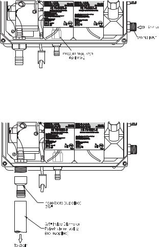
OPERATING DESCRIPTION
BROMINE MEASUREMENT
Referring to the drawing on page 10 and the Fluidic Diagram on page 17, the Sample Line is connected to the instrument at the Sample Port (#17); an internal Regulator (#15) reduces the inlet pressure from a maximum of 4 bar (57.2 psi) down to 1 bar (14.3 psi); from the Regulator a nylon tube is connected to the input of the Electrovalve (#21). The output of the valve goes to the Drain Port (#11) and then to the Measuring Cell (#7). An optional Filter can be installed to the sample port if the stream is excessively turbid.
The sample coming from the line normally flows through the Measuring Cell (#7). It goes out from the Measuring Cell through the Drain Tube (#8) and the Output Port (#9).
The Measuring Cell is accessible from the port placed on the top (#6) for speedy cleaning and maintenance.
During the 100 seconds preceding the sampling, the analyzer solenoid input valve is open to allow sample flow to flush the colorimeter cell. Every 3 to 90 minutes (user selectable), the electrovalve closes stopping the sample flow and leaving the sample cell full of fresh sample. Cell volume is controlled by an overflow gateway.
As the sample inlet electrovalve closes, a series of measurements (with LED on and off) of the unreacted sample is taken to determine an average blank level prior to reagent addition.
The measurement of sample blank signal permits compensation for any turbidity or natural color, and provides the zero reference point for the measurement.
The two channel Peristaltic Pump (#5) starts rotating causing a precise quantity of buffer and indicator (#13 and #16) to enter the colorimeter sample cell. Here a magnetically coupled stirrer mixes the reagents with the sample.
After a delay for the color development, a series of measurements (with LED on and off) are taken (sample level) to determine an average bromine concentration measurement. The reacted sample signal is then measured and displayed.
This sequence is repeated every 3 to 90 minutes (user-selectable).
1 6

METHOD OF ANALYSIS
The available b r o m i n e oxidizes the b r o m i n e reagents at a pH between 5.5 and 6.0 to formamagentacolored compound. The intensity of the resulting color is proportional to the concentration of bromine in the sample.
pH AND TEMPERATURE MEASUREMENT
The HI 1005 pH/temperature probe provides at the out port a potential proportional with the pH. The temperature is measured with PT100 platinum sensor.
For increased accuracy the pH is corrected with temperature and with the calibration coefficients. Up to 2 buffers can be used for calibration.
The temperature can be displayed in °C or °F.
The probe can withstand pressure up to 6 bar (87 psi).
ORP MEASUREMENT
The HI 2008 probe provides at the out port a potential proportional with the ORP value. The value is directly displayed in mV.
The probe can withstand pressure up to 6 bar (87 psi).
1 7

INITIAL PREPARATION AND INSTALLATION
INSTALLATION PERSONNEL
Installation of the PCA 311-331 Bromine, pH, ORP and temperature analyzers should be undertaken by persons with technical knowledge of the dangers associated with chemical exposure and electrical shock.
HannaInstrumentsassumesthatpersonsperformingtheinstallation tasks are aware of the appropriate safety procedures.
CAUTION: Review the Material Safety Data Sheets (MSDS) before handling the supplied chemical reagents.
LOCATION OF THE INSTRUMENT
Analyzer Location
Locate the analyzer as close as is reasonably possible to the point where the sample is withdrawn from the product stream (referred to as the sampling point).
The instrument should be mounted indoors, out of direct sunlight. Instrument operating temperature is 5 to 40°C (41 to 104°F).
Sampling Point Location
Locate the sampling point to obtain a truly representative sample from the product stream. For example, be sure the sampling point is well downstream from a Bromine and acid / alkali feed. This assures that adequate mixing and reaction of the Bromine and acid / alkali before a sample is extracted.
HYDRAULIC CONNECTIONS
Note: Hydraulic connections should be installed only by qualified personnel to assure conformity to applicable plumbing codes.
Sample Line Installation
Direct routing of sample lines is recommended.
If the large process pipes are horizontal, taps should be inserted vertically in the middle of the pipe to avoid pulling sediment from the bottom or air bubbles from the top of the pipe into the sample line.
A 1/2 BSP sample input fitting allows direct connection to the optional input filter.
1 8
Sample line pressure should be between 0.07 and 4 bar (1 and 57.2 psi) with an ideal pressure of 0.7 bar (10 psi).
Drain Line Installation
The drain hose fitting is a 20 mm (3/4”) hose barb on the bottom of the instrument enclosure. An air gap between the
end of the drain hose and the drain is recommended to prevent any back flow into the instrument in the event of drain blockage.
Return Line Installation
The return hose fitting is a 12 mm (1/2”) hose barb on the bottom of the regulator output port and should always be connected even when pressure is below 1 bar.
1 9
INSTALLING THE INPUT FILTER
In order to ensure maximum accuracy of measurements, it is recommended to have always clear sample, with suspended particles smaller than 0.5 μm. This can be achieved by installing two filters before the sample input.
The type of filters depends on the quality 


 of the water: the first filter should have 50-
  100 μm pore size, whereas in any case the second filter, the one closer to the analyzer, has to be 0.5 μm.
For correct installing procedure and maintenance, see the instructions of filters.
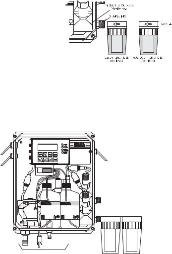
INSTALLING THE pH AND ORP PROBES
To mount the pH and ORP probes, first turn off the analyzer. Unscrew the closing caps from the electrode holder and remove the protective cap from electrodes and electrodes connectors.
BROMINE |
Bromine/pH/ORP |
Analyzer |
PCA-331 |
 ORP probe
PCA 301 |
PCA 301 |
REAGENTS |
REAGENTS |
HI 70498B-0 |
HI 70498A-0 |
BROMINE BUFFER SOLUTION |
BROMINE INDICATOR SOLUTION |
 PH probe
ScrewthepHprobe(HI1005)inthelowerpositionandtheORPprobe (HI 2008) in the higher position and assure that no leakage occurs.
2 0
Only after the probe is in final position connect the probe to the dedicated connector. Lock the connector with the built in nut.
 Warning: Never connect or disconnect the probes when the analyzer is powered on.
INSTALLING THE PUMP TUBES
Locate the analyzer reagent tubes in the accessory kit. Each tube is composed of three sections. The sections are joined together by plastic connectors with plastic collars at the ends of the center section.
HI 70479 HI 70474 or HI 70475 HI 70473
Locate the peristaltic pump.
Feed one tube from the shorter
end section behind the pump rollers from the right side of the
pump. Seat the plastic collar at the right end of the center section of tubing into the lower
right indentation hole of the pump face.
Grasp the other plastic collar and pull, stretching the center section, and place the grommet in the lower left indentation hole.
Repeat this process with the second pump tube, placing it in the upper indentation holes.
To "Y" Connector
and Measuring Cell
From Indicator Bottle
From Buffer Bottle |
To "Y" Connector |
|
and Measuring Cell |
2 1

Separate reagent caps are provided in the accessory kit. Put the supplied caps onto each reagent bottle prior to installing them. Place the indicator bottle (HI 70498A) on the right and the buffer bottle (HI 70498B) on the left.
Note: Add the content of 5 HI 70452 sachets, DPD Compound, to the Indicator Solution prior to installing it.
Connect the longer tube 


 ends on the left side of the
pump to the reagent bottle cap insert fitting.
Connect the short ends in the right side of the pump to the measuring cell reagent input port through the
“Y” connector.
ELECTRICAL CONNECTIONS
A power cable (3 mt.) is provided with your analyzer. However, if access to the terminal block is required, see below.
 Warning: Electrical connections should be installed only by qualified personnel to assure conformity to applicable electrical codes. Unplug the meter before any electrical connection.
2 2
Power Connection
Power connections are made at a terminal block located in the center of the electrical compartment to the right of the fuses. Hard wiring with 13 mm (½”) conduit is recommended and usually required by most municipal electrical codes.
Warning:Before connecting the instrument to the line:
1)Check the label near the fuses for proper voltage.
2)Be sure the power cord is not connected to the line.
3)Open front panel.
4)Remove the cover screws (Allen head).
5)Do not remove peristaltic pump or motor.
6)Unplug all alarms and recorder jacks.
Feed the power cord through the watertight grommet and tighten the grommet nut. See the picture below for proper wire connections.
Main Power PCB
Electrovalve
Line Filter |
Transformer |
|
|
|
Ground screw |
|
|
Terminal |
|
|
block |
|
|
Neutral |
|
|
Watertight |
|
1 |
Grommet and |
|
|
Nut Assembly |
 Main Power
Cord
Earth
Phase
24 VAC
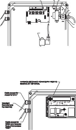
Recorder Output and Relay Access
Hard wiring for alarms and relays recorder output and serial communication can be accomplished through four watertight connectors on the left side of the enclosure, by passing wires through the rubber grommet and tightening the nut as described earlier.
Refer to the drawings for proper wire connections.
2 3
 Loading...