


Hg80b03508a
Installation, Operation and Maintenance
MODEL HG80 035 HG80 050
B
HG80 085BHG80 100
HG80 135
B
B
B
HG80 070
HG80 115
B
B
CATEGORY I NATURAL GAS AND LP GAS
MID EFFICIENCY WARM AIR FURNACE
TABLE OF CONTENTS
INTRODUCTION . . . . . . . . . . . . . . . . . . . . . . .1
SAFETY . . . . . . . . . . . . . . . . . . . . . . . . . . . . . .1
CODES . . . . . . . . . . . . . . . . . . . . . . . . . . . . . .2
FURNACE SIZING . . . . . . . . . . . . . . . . . . . . . .3
LOCATION of UNIT . . . . . . . . . . . . . . . . . . . .3
INSTALLATION POSITIONS . . . . . . . . . . . . . . .4
AIR CONDITIONING . . . . . . . . . . . . . . . . . . . .4
INSPECTION/ACCESS PANEL . . . . . . . . . . . . .4
CLEARANCES . . . . . . . . . . . . . . . . . . . . . . . . .5
DIMENSIONS . . . . . . . . . . . . . . . . . . . . . . . . .5
DUCTWORK . . . . . . . . . . . . . . . . . . . . . . . . . .6
DETERMING COMBUSTION AIR . . . . . . . . . .7
FURNACE VENTING . . . . . . . . . . . . . . . . . . . .8
GAS SUPPLY . . . . . . . . . . . . . . . . . . . . . . . . .13
CONVERSIONS . . . . . . . . . . . . . . . . . . . . . . .14
HIGH ALTITUDE & AIRFLOW
SPECIFICATION TABLES . . . . . . . . . . . . . . . .15
ELECTRICAL SPECIFICATIONS . . . . . . . . . . .16
START UP PROCEDURES/
SEQUENCE OF OPERATION . . . . . . . . . . . . .18
AIR FLOW . . . . . . . . . . . . . . . . . . . . . . . . . . .20
ADJUSTING BLOWER SPEEDS . . . . . . . . . . .20
MAINTENANCE
TROUBLESHOOTING . . . . . . . . . . . . . . . . . .22
WIRING DIAGRAM . . . . . . . . . . . . . . . . . . . .26
. . . . . . . . . . . . . . . . . . . . . .
21
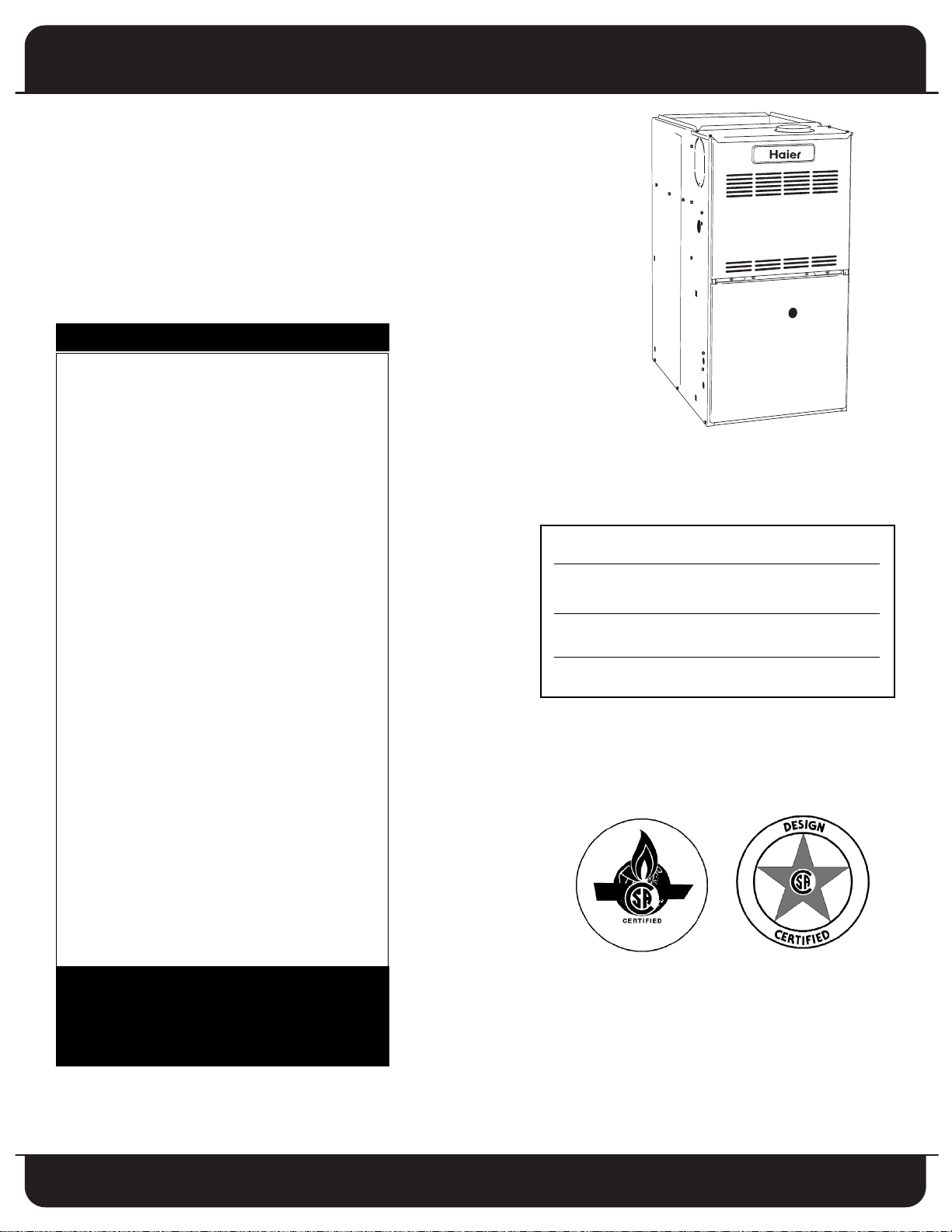
For future reference write down the model, serial
number, and date of purchase. Use these numbers in
any correspondence or service calls concerning your
furnace.
Model
Serial Number
Date of Purchase
Keep these instructions for future reference.
Please read the operating instructions and safety
precautions carefully and thoroughly before installing
and operating your furnace. Keep this manual in a
safe place for future reference.
USER’S INSTRUCTION GUIDE
LOCATED AFTER PAGE 266 OF THIS
INSTALLATION, OPERATION AND
MAINTENANCE MANUAL

NTRODUCTION
I
This gas fired midefficiency (non-condensing) furnace is an
p flow, counterflow or horizontal flow warm air furnace
u
suitable for residential and light commercial heating
applications from 35,000 to 135,000 BTU/Hr.
his appliance is a CGA / AGA design certified as a Category I
T
chimney vent central forced air furnace with all combustion
air supplied from the ambient air around the furnace.
urnace models HG80B050, HG80B070, HG80B085,
F
HG80B100,HG80B115 and HG80B135 may be field
converted from natural gas to LP gas using Kit , or may be
field converted from LP gas to natural gas using Kit .
Contact manufacturer for conversion kit availability.
urnace
F
*
LP, and is not approved for conversion.
The furnace is shipped completely assembled. Please inspect
for damage, as the furnace is unpacked.
model HG80B035 cannot be converted to
SAFETY
Throughout the manual, symbols and words are used to
draw attention to potentially hazardous conditions.
DANGER
THIS INDICATES AN IMMINENTLY HAZARDOUS
SITUATION WHICH, IF NOT AVOIDED, WILL RESULT IN
DEATH OR SERIOUS INJURY.
WARNING
THIS INDICATES A POTENTIALLY HAZARDOUS
SITUATION WHICH, IF NOT AVOIDED, COULD RESULT IN
DEATH OR SERIOUS INJURY.
CAUTION
THIS INDICATES A POTENTIALLY HAZARDOUS
SITUATION, WHICH, IF NOT AVOIDED, MAY RESULT IN
MINOR OR MODERATE INJURY.
. Always install furnace to operate within the furnace’s
6
intended temperature rise range with a duct system
which has an external static pressure within the
allowable range, as specified in the Furnace Sizing
section on page 3, the Ductwork section on page 6, and
he Airflow section on page 20 of these instructions
t
7. When a furnace is installed so that the supply ducts carry
air circulated by the furnace to areas outside the space
ontaining the furnace, the return air shall also be
c
handled by duct(s) sealed to the furnace casing and
terminating outside the space containing the furnace.
(Furnace for heating the home located in the attached
arage, for example).
g
8. A gas fired furnace for installation in a residential
garage must be installed so that the burners and ignitor
are no less than 18 inches above the floor. The furnace
must be located, or protected to avoid physical damage
by vehicles.
THIS FURNACE IS NOT TO BE USED FOR TEMPORARY
9.
HEATING FOR BUILDINGS UNDER CONSTRUCTION.
10. Nox Baffles are factory installed in the heat exchanger
tubes of this furnace, and must remain installed
regardless of fuel being used.
DANGER
DO NOT INSTALL THIS FURNACE IN A MOBILE HOME!
THIS FURNACE IS NOT APPROVED FOR INSTALLATION IN
A MOBILE HOME. DOING SO COULD CAUSE FIRE,
PROPERTY DAMAGE, PERSONAL INJURY OR LOSS OF
LIFE.
WARNING
THE FURNACE CONTAINS FOIL COVERED FIBERGLASS
INSULATION. INHALATION OF FIBERGLASS PARTICLES IS
ASSOCIATED WITH RESPIRATORY DISEASE INCLUDING
CANCER.
SAFETY RULES:
1. Use this furnace only with type of gas approved for this
furnace. Refer to the furnace rating plate.
2. Install this furnace only in dry indoor locations
(protected from weather).
3. Provide adequate combustion and ventilation air to the
furnace space as specified in the Determining
Combustion Air section on page 7 of these instructions.
4. Combustion products must be discharged outdoors.
Connect this furnace to an approved vent system only, as
specified in the Furnace Venting section on page 8 of
these instructions.
5. Never test for gas leaks with an open flame. Use a
commercially available soap solution made specifically
for the detection of leaks to check all connections as
specified in the Gas Supply section on page 13 of these
instructions.
WARNING
THE FUEL SUPPLIER NORMALL
GAS AND PROP
MAY NOT BE PERCEIVABLE. INSTALLATION OF UL AND
CUL RECOGNIZED FUEL GAS DETECTORS INSTALLED IN
ACCORDANCE WITH THEIR MANUFACTURER’S
INSTRUCTIONS IS RECOMMENDED AS AN ADDITIONAL
MARGIN OF SAFETY
ANE. IN SOME CASES, THE ODORANT
.
Y ODORIZES NATURAL
DANGER
FIRE OR EXPLOSION HAZARD
If the information in these instructions is not followed
exactly, a fire or explosion may result, causing property
damage, personal injury or loss of life.
CAUTION
MAKE SURE TO REMOVE FOAM BLOWER HOUSING
SHIPPING SUPPORTS BEFORE OPERATING FURNACE.
SHIPPING SUPPORTS ARE LOCATED ON THE BOTTOM
RIGHT AND BOTTOM LEFT SIDES OF BLOWER HOUSING.
1
WARM AIR FURNACE
DANGER
WHAT TO DO IF YOU SMELL GAS:
• DO NOT TRY TO LIGHT ANY APPLIANCE
• DO NOT TOUCH ANY ELECTRICAL SWITCH; DO NOT
USE ANY PHONE IN YOUR BUILDING
IMMEDIATELY CALL YOUR GAS SUPPLIER FROM A
•
EIGHBOR’S PHONE, OR A CELLULAR PHONE FROM A
N
LOCATION WELL AWAY FROM THE BUILDING.
FOLLOW THE GAS SUPPLIER’S INSTRUCTIONS.
IF YOU CANNOT REACH YOUR GAS SUPPLIER, CALL
•
THE FIRE DEPARTMENT
• DO NOT ENTER THE BUILDING UNTIL AUTHORIZED TO
DO SO BY THE GAS SUPPLIER OR THE FIRE
DEPARTMENT
IMPROPER INSTALLATION, OPERATION, ADJUSTMENT,
ALTERATION, SERVICE OR MAINTENANCE CAN CAUSE
INJURY, PROPERTY DAMAGE OR LOSS OF LIFE. REFER TO
THIS MANUAL FOR PROPER INSTALLATION, OPERATION,
VICE, AND MAINTENANCE INSTRUCTIONS.
SER
A QUALIFIED INSTALLER, SERVICE AGENCY OR
THE GAS SUPPLIER MUST PERFORM
INSTALLATION AND SERVICE.
DO NOT DESTROY THIS MANUAL
PLEASE READ CAREFULLY AND KEEP IN A SAFE PLACE
FOR FUTURE REFERENCE BY A SERVICE TECHNICIAN.
WARNING
THESE INSTRUCTIONS ARE INTENDED AS AN AID TO
QUALIFIED SERVICE PERSONNEL FOR PROPER
INSTALLATION, ADJUSTMENT AND OPERATION OF THIS
FURNACE. READ THESE INSTRUCTIONS THOROUGHLY
BEFORE ATTEMPTING INSTALLATION OR OPERATION.
FAILURE TO FOLLOW THESE INSTRUCTIONS MAY RESULT
IN IMPROPER INSTALLATION, ADJUSTMENT, SERVICE OR
MAINTENANCE, POSSIBLY RESULTING IN FIRE,
ELECTRICAL SHOCK, CARBON MONOXIDE POISONING,
EXPLOSION, PROPERTY DAMAGE, PERSONAL INJURY OR
DEATH.
DO NOT STORE OR USE GASOLINE OR OTHER
FLAMMABLE VAPORS AND LIQUIDS, OR OTHER
COMBUSTIBLE MATERIALS IN THE VICINITY OF THIS OR
ANY OTHER APPLIANCE.
WARNING
THE EXHAUST GASES FROM THIS FURNACE CONTAIN
CHEMICALS, WHICH ON SOME OCCASIONS MAY
INCLUDE CARBON MONOXIDE (CO). CARBON
MONOXIDE IS AN ODORLESS, TASTELESS, CLEAR
COLORLESS GAS, WHICH IS HIGHL
CONCENTRA
DEFECTS AND OTHER REPRODUCTIVE HARM.
UL AND CUL RECOGNIZED CO DETECTORS ARE
RECOMMENDED FOR ALL BUILDINGS EQUIPPED WITH
FOSSIL FUEL BURNING APPLIANCES. ALL CO DETECTORS
SHOULD BE INST
MANUFACTURER’S INSTRUCTIONS AND APPLICABLE
LOCAL BUILDING CODES.
TIONS ARE SUSPECTED OF CAUSING BIR
ALLED IN ACCORDANCE WITH THEIR
Y TOXIC. EVEN LOW
TH
DANGER
HEN THIS FURNACE IS INSTALLED IN A RESIDENTIAL
W
GARAGE, IT MUST BE INSTALLED SO THE BURNERS AND
IGNITION SOURCE ARE LOCATED NO LESS THAN 18
INCHES ABOVE THE FLOOR TO PREVENT THE RISK OF
IGNITING FLAMMABLE VAPORS WHICH MAY BE
RESENT IN THE GARAGE.
P
THE FURNACE MUST BE LOCATED OR PROTECTED TO
AVOID PHYSICAL DAMAGE BY VEHICLES.
FAILURE TO HEED THESE WARNINGS CAN CAUSE A FIRE
OR EXPLOSION, RESULTING IN PROPERTY DAMAGE,
PERSONAL INJURY OR LOSS OF LIFE.
CODES:
This furnace must be installed:
• In accordance with all local codes, bylaws and
regulations by those authorities having jurisdiction
• In the United States, this furnace must be installed in
accordance with the current ANSI Z223.1 (NFPA 54)
National Fuel Gas Code
• In Canada, this furnace must be installed in
accordance with the current CAN/CGA -B149
Installation Code for Fuel Burning Appliances
Electrical connections must be made in accordance
with:
• Any applicable local codes, bylaws and regulations
• Canada: current edition of CAN/CSA C22.1, Canadian
Electrical Code (Part 1)
• United States: current edition of ANSI/NFPA 70,
National Electrical Code
Codes and additional information may be obtained
from:
•
American Gas Association
1515 Wilson Boulevard
Arlington, VA, 22209
703-841-8400
National Fire Protection Association
•
1 Batterymarch Park
Quincy, MA, 02269-9101
617-770-3000
•
Canadian Gas Association
Suite 1, 243 Consumers Road
North York, ON, M2J 5E3
416-498-1994
2

URNACE SIZING
TABLE 1A
FURNACE TEMPERATURE RISE
Fur nac e Mod
Model
el Tem per atu re
Rise
35 – 65 F
30 – 60 F
35 – 65 F
30 – 60 F
35 – 65 F
30 – 60 F
30 – 65 F
TAB
LE 1B
TYPICAL A IR FLOW
CF M Re qu ired for a T of:
35 45
55 65
03508A
05012A
07012A
07016A
08512A
08516A
10012A
10016A
10020A
11520A
737 574 469 397
1053 819 670 567
1433 1114 912 771
1433 1114 912 771
1791 1393 1140 964
1791 1393 1140 964
2107 1639 1341 1134
2107 1639 1341 1134
2107 1639 1341 1134
2423 1884 1542 1305
13520A
2844 2212 1810 1532
03508A
05012A
07012A
07016A
08512A
08516A
10012A
10016A
10020A
11520A
13520A
F
The maximum hourly heat loss for each heated space shall
e calculated in accordance with the procedures described
b
in Manual J titled, "Load Calculation" published by the Air
Conditioning Contractors of America, or by any other
method which is suitable for local conditions, provided the
esults obtained are in substantial agreement with, and not
r
less than those obtained using the procedure described in
their manual.
n Canada, the maximum hourly heat loss for each heated
I
space shall be calculated in accordance with the procedures
described in the manuals of the Heating, Refrigeration and
Air Conditioning Institute of Canada (HRAI), or by any other
method which is suitable for local conditions, provided the
results obtained are in substantial agreement with, and not
less than those obtained using the procedure described in
their manuals.
If the installation is a retrofit application, do not rely on the
capacity of the existing heating equipment as a method to
size the new furnace. Many of the heat transfer multiples
listed in earlier versions of load calculation manuals were
much higher than those listed in more recent editions. It is
possible that energy saving measures have been completed
since the installation of the existing furnace. This might
include additional insulation in the attic or walls, the
application of sprayed foam insulation, the addition of
storm windows and doors, weather stripping, caulking, etc.
Many of the older furnaces were equipped with large belt
drive blower systems, operating at low RPMs. If replacing an
existing furnace, be sure that the existing ductwork can
handle the amount of airflow necessary for a reasonable
temperature rise. Most older gas furnaces operated with a
system temperature rise of 70 - 100°F. This series furnace has
been designed for operation with a system temperature rise
(DT) of 35 - 65°F or 30 – 60°F depending on which model is
being installed. See Table 1A below. If the furnace selected
has an identical output capacity as the original furnace, a
substantial increase in system airflow will be required. See
able 1B below
T
Existing ductwork should be assessed for its air handling
capabilities. For residential applications, the recommended
air velocity of a supply air trunk duct is 700 feet per minute
(fpm), and should not exceed 900 fpm. The recommended
air velocity of a supply air branch run is 600 fpm, and should
not exceed 900 fpm. These values are slightly lower for
flexible ducting. The recommended air velocity of a return
air trunk duct is 600 fpm, and should not exceed 700 fpm.
The recommended and maximum air velocity of a return air
branch is 600 fpm.
.
he equal friction chart, as published by ASHRAE and HRAI,
T
is the basis for the various air duct calculators available
through heating supply companies.
NOTE: The return air system is equally as important as the
supply air system. An undersized return air system will
prevent sufficient quantities of air from reaching the supply
air system, properly sized or otherwise, and will
consequently reduce the service life of the furnace and its
components.
LOCATION of UNIT
GENERAL:
1. The furnace is not weatherized. Select a dry indoor
location.
2. Select a location where the furnace venting can be
routed between the furnace and the chimney or B-Vent
with a minimum of lengths and fittings. Be sure to
check that the proposed routing will meet code
requirements with respect to minimum clearances.
3. Select a location as near as possible to the existing or
proposed duct system.
4. The furnace location must permit access for servicing,
and be within the clearance to combustibles guidelines
as marked on the appliance rating plate.
5. The furnace should be installed on a firm base when
installed in the upflow position. This is typically a
concrete floor if installing the furnace in a basement.
6. If the furnace is being installed so that the return air
will enter through the bottom, the perimeter of the
furnace must be properly supported.
7. When installed in the horizontal position, the furnace
may be supported from the bottom, or suspended.
8. When installed in the down flow position on a
combustible floor, subbase kit is required
(contact manufacturer for availability).
OTHER CONSIDERATIONS:
• This furnace is not to be used for temporary heating of
buildings or structures under construction.
• If this furnace is to be used with air conditioning and is
to be installed in an area over a finished ceiling or
living area, install a field fabricated auxiliary drain pan
under the furnace to protect that area from accidental
condensate spills. The auxiliary pan should be large
enough to collect accidentally spilled condensate from
the air conditioning evaporator coil assembly if
applicable. Follow local codes.
These furnaces are approved for installation in attics,
•
alcoves, utility rooms, closets and crawlspaces. If this
furnace is to be installed in a utility room, be sure that
it is located in such a way as to allow access for
servicing or the removal of any other appliance, (hot
water heater, for example).
If the furnace is to be installed in a garage, the burners
•
must be a minimum of 18 inches (460 mm) above the
floor.
If the furnace is to be installed in a commercial (repair)
•
garage, the burners must be a minimum of 4.5 feet
(1375 mm) above the floor.
The furnace must be protected from physical damage
•
by metal barriers or other acceptable means.
3
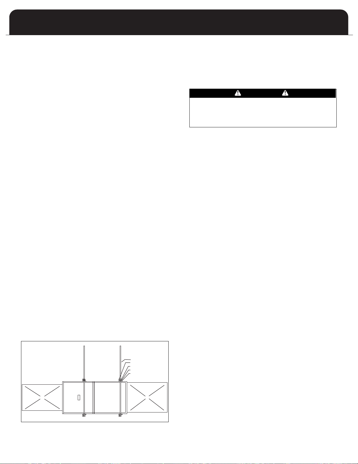
SUGGESTED METHOD FOR
SUSPENDING HORIZONTAL FURNACE
ALLOW ENOUGH ANGLE
IRON OVERHANG TO
PERMIT OPENING THE
BLOWER DOOR
3/8 INCH THREADED ROD
2 INCH ANGLE IRON
JAM NUTS
LOCK WASHER
FLATWASHER
SUPPLY AIR PLENUM
RETURN AIR PLENUM
If the furnace is to be located in an area where the
•
combustion air is laden with chemical compounds such
as bromine, chlorine or fluorine, as may be found in
swimming pool chemicals, laundry detergents, etc., use
outdoor air for combustion. These compounds when
xposed to flame, form acids, which attack the heat
e
exchanger and other components.
A partial list of these contaminants includes:
- Aerosols, particularly CFC based aerosols
Air fresheners
-
- “Airplane” glue and similar cements
- Ammonia, as is commonly found in permanent wave
solutions used in women’s hair dressing salons
- Anti-static fabric softeners used in clothes dryers
- Carbon tetrachloride
- Chlorinated cleaners and waxes
- Chlorine and bromine based swimming pool chemicals
and treatments
- Deicing salts or chemicals, rock salt, etc.
- Dry cleaning solutions such as perchloroethylene
- Halogen based refrigerants including R-12 and R-22
- Hydrochloric acid, muriatic acid, or other acid based
masonry washing compounds
- Polyurethane and similar derivatives fumes
- Printer’s inks, paint removers, furniture strippers,
varnishes, varsol, toluene, etc.
- Water softener salts and chemicals
INSTALLATION POSITIONS
NONSUSPENDED INSTALLATION
Maintain clearances to combustibles as outlined in Table 2
on page 5. The furnace must be supported in such a way as
to not allow twisting or sagging of the cabinet.
SUSPENDED INSTALLATION
Refer to Figure 1 (below). Maintain clearances to
combustibles as outlined in Table 2 on page 5. The furnace
may be suspended by field fabricating a cradle of angle iron
and threaded rod. Secure the furnace with 2 inch minimum
slotted angle or equivalent, as shown in Figure 1 (below).
The furnace must be supported in such a way as not to
allow twisting or sagging of the cabinet. Position the
supports so as not to interfere with accessing the burner
and blower compartments.
FIGURE 1: SUSPENDED INST
ALLATION
WARM AIR FURNACE
PFLOW INSTALLATION
U
This furnace comes assembled for installation in the upflow
osition and ready for vertical venting. In the event that the
p
furnace will be installed in another position, the following
guidelines should be followed.
COUNTERFLOW INSTALLATION
WARNING
HEN INSTALLED IN THE COUNTERFLOW POSITION ON
W
A COMBUSTIBLE FLOOR, SUBBASE KIT IS
REQUIRED. FAILURE TO INSTALL SUBBASE KIT COULD
RESULT IN FIRE, DEATH OR SERIOUS INJURY.
The opening in the floor must provide adequate clearances
to the combustible material.
According to the Clearances to Combustibles Table 2 on
page 5, 1/2 inches clearance will be required between the
plenum and the combustible material. If installed on a
non-combustible material, zero clearance is required.
Inducer position changes required shall be performed in
accordance with the inducer rotation instructions in the
Furnace Venting section on page 8 of this manual. In the
counterflow installation, this furnace can only vent through
the left or right side of the furnace.
HORIZONTAL INSTALLATION
Inducer position changes required shall be performed in
accordance with the inducer rotation instructions in the
Furnace Venting section on page 8 of this manual. In the
horizontal installation, it is not permissible to vent
downwards. Therefore the orientation of left or right
horizontal position will determine the inducer orientation.
NOTE: It is not permissable to use a rear return on this
furnace although side and end returns may be used.
AIR CONDITIONING
This furnace may be used as part of an air conditioning
system. The furnace wiring and control system are “air
conditioning ready”. There are the following factors to
consider:
• The air conditioning evaporator coil must be
downstream of the heat exchanger. The cooled air
passing over the warm ambient air inside the heat
exchanger tubes can cause condensation inside the
tubes, resulting in corrosion and premature failure.
A parallel duct system can be installed to direct the air
•
from the furnace through the evaporator coil only. Use
dampers or other means to bypass the heat exchanger.
If [summer/winter] dampers are used, they should be
interlocked to prevent system operation unless the
dampers are in the full open or full closed position.
INSPECTION / ACCESS PANEL
If an air conditioning coil is not to be used in the supply air
plenum, it is recommended that the outlet duct be provided
with a removable access panel, which is accessible when
installed so the heat exchanger may be viewed for possible
openings using light assistance or a probe that can be
inserted for sampling the air stream. The access cover must
be fabricated in such a manner as to prevent leaks.
4
DIMENSIONS (Inche
MODEL WI DTH DEPTH HEIGHT SUPPLY
A
35-2 14-1/2 29 35 13-1/2 x 19
50-3 14-1/2 29 35 13-1/2 x 19
70-3 16 29 35 15 x 19
70-4 17-1/2 29 35 16-1/2 x 19
85-3 17-1/2 29 35 16-1/2 x 19
85-4
4100- 20-1/2 29 35 19-1/2 x 19
100-5 20-1/2 29 35 19-1/2 x 19
115-5 22 29 35 21 x 19
MODEL RETURN
S
35-2 14 x 22 13-1/2 x 22 1/2 3
1
50-3 14 x 22 13-1/2 x 22 1/2 3
1
70-3 14 x 22 14-1/2 x 22 3/4 4
70-4 14 x 22
2
85-3 14 x 22 14-1/2 x 22 1-1/2 4
85-4
4100- 14 x 22 16 x 22 2-1/4 4
100-5 14 x 22
2
115-5 14 x 22
2
1
Vent outlet 4” -
2
Two return air openings required
G
A
H
C
G
B
F
D
J
L
L
K
LEARANCES
UPFLOW
COUNTERFLOW
HORIZONTAL
1" 0" 2"
1" 1" 2.5"
.5" .5" .5"
3.5"* 3.5"* 3.5"*
0" 0" 0"
0" 0" 1"**
0"*** 0"**** 0"
6" 6" 6"
1" 1" 1"
CLOSET
CABINET
CLOSET
CABINET
CLOSET
CABINET
UNIT TOP
PLENUM
TOP/BOTTOM
PLENUM SIDES
UNIT FRONT
UNIT BACK
UNIT SIDES
ENCLOSURE
UNIT BASE
FLUE
PIPE
C VENT
B VENT
03508A
05012A
07012A
07016A
08512A
08516A
10012A
10016A
10020A
11520A
13520A
03508A
05012A
07012A
07016A
08512A
08516A
10012A
10016A
10020A
11520A
13520A
C
Table 2 (below) provides the certified clearances to
ombustibles.
c
MPORTANT:
I
This furnace requires a minimum of 24-inches of front
clearance for service purposes. For this purpose, service
clearance takes precedence over clearance to combustibles.
TABLE 2: CLEARANCES TO COMBUSTIBLES
* 24 inches required for service
** Supply air end 1 inch / return air end 0 inches
*** Certified for closet installation on combustible flooring
**** Certified for installation on combustible flooring
See the appliance rating plate affixed to the furnace
for specific model number, serial number and
clearance to combustibles information.
COMBUSTIBLE MATERIAL MUST NOT BE PLACED ON OR
AGAINST THE FURNACE JACKET.
THE AREA AROUND THE FURNACE MUST BE KEPT CLEAR
AND FREE OF ALL COMBUSTIBLE MATERIALS INCLUDING
GASOLINE AND OTHER FLAMMABLE VAPORS AND
LIQUIDS.
PLACEMENT OF COMBUSTIBLE MATERIALS ON, AGAINST
OR AROUND THE FURNACE JACKET CAN CAUSE AN
EXPLOSION OR FIRE RESULTING IN PROPERTY DAMAGE,
PERSONAL INJUR
THE HOMEOWNER SHOULD BE CAUTIONED THA
FURNACE AREA MUST NOT BE USED AS A BROOM
CLOSET OR FOR ANY OTHER STORAGE PURPOSE.
UPFLOW FURNACES ARE DESIGN CERTIFIED FOR
INSTALLATION ON COMBUSTIBLE FLOORS. THIS SHALL
BE INTERPRETED AS A WOOD FLOOR ONLY
THE FURNACE MUST NOT BE INSTALLED DIRECTLY ON
CARPETING, VINYL TILE, OR OTHER COMBUSTIBLE
MATERIAL EXCEPT WOOD. INSTALLATION ON
COMBUSTIBLE MATERIAL CAN RESULT IN FIRE, CAUSING
PROPER
only when installed on special base .
DANGER
TY DAMAGE, PERSONAL INJUR
Y OR LOSS OF LIFE.
.
Y OR DEA
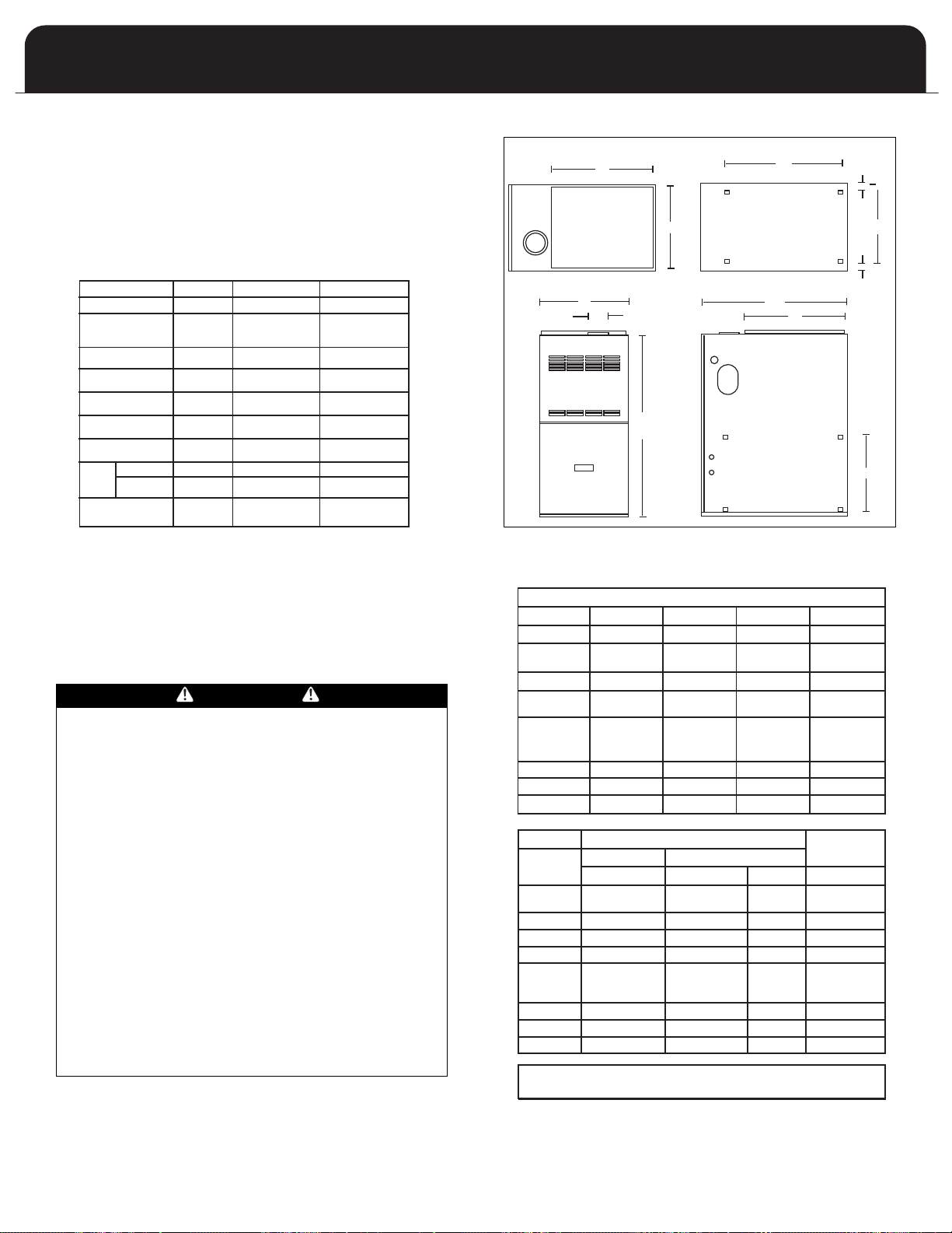
IGURE 2: DIMENSIONS
F
TABLE 3: DIMENSIONS
DIMENSIONS (Inches)
MODEL WIDTH DEPTH HEIGHT SUPPLY
T THE
TH.
5
MODEL RETURN
1
Vent outlet 4” - Use reducer fittings.
2
Two return air openings required
ABCFx G
14-1/2 29 35 13-1/2 x 19
16 29 35 15 x 19
17-1/2 29 35 16-1/2 x 19
20-1/2 29 35 19-1/2 x 19
20-1/2 29 35 19-1/2 x 19
22 29 35 21 x 19
22 29 35 21 x 19
SIDE BOTTOM
VENT
D x E J x K L H
14 x 22 13-1/2 x 22 1/2 3
14 x 22 14-1/2 x 22 3/4 4
2
14 x 22
14-1/2 x 22 1-1/2 4
1
14 x 22 14-1/2 x 22 1-1/2 4
14 x 22 16 x 22 2-1/4 4
2
14 x 22
14 x 22
14 x 22
2
2
16 x 22 2-1/4 4
19 x 22 1-1/2 5
19 x 22 1-1/2 5
1
1
WARM AIR FURNACE
UCTWORK
D
Proper airflow is required for the correct operation of this
urnace. Insufficient airflow may cause erratic operation,
f
could cause the furnace to cycle on the high temperature
limit, and may damage the heat exchanger. Excessive
airflow may result in an excessively noisy duct system and
may result in undesirable consequences such as creating
ncomfortable drafts and causing drapes or curtains to
u
blow around.
If air conditioning is to be used with the furnace, the duct
ystem must be capable of delivering the correct amount of
s
airflow for each system.
The ductwork should be sized and constructed in
accordance with accepted industry standards. Duct sizing
and construction information may be obtained from:
• A.C.C.A. (Air Conditioning Contractors of America)
• A.S.H.R.A.E. (American Society of Heating,
Refrigeration and Air Conditioning Engineers)
• H.R.A.I. (Heating, Refrigerating and Air Conditioning
Institute (Canada)
• S.M.A.C.N.A. (Sheet Metal and Air Conditioning
Contractors’ National Association (United States)
All of the above professional organizations have duct sizing
manuals available.
The total static pressure drop of the air distribution system
should not exceed 0.5 inches water column.
NOTE:
UNITS 07016A,10020A,11520A AND 13520A MUST HAVE
DUAL RETURN AIR INLETS FOR OPTIMAL AIRFLOW AND
AIR FILTRATION. IF NOT SPECIFICALLY STATED BY THE
FILTER MANUFACTURER, FOR EFFECTIVE AIR FILTRATION,
ASSUME A MAXIMUM VELOCITY OF 300 FPM FOR DISPOSABLE
TYPE FILTERS, OR 600 FPM FOR PERMANENT TYPE FILTERS.
GUIDE:
Filter free area (in2) = 144 x (CFM / desired velocity (fpm))
IMPORTANT: Some high efficiency filters have a greater
than normal resistance to airflow. This can adversely affect
furnace operation. Ensure to check the airflow when using
any filter.
ARNING
W
DO NOT, UNDER ANY CIRCUMSTANCES, CONNECT
RETURN OR SUPPL
OTHER HEA
INSERT, STOVE, ETC. DOING SO MAY RESULT IN FIRE,
CARBON MONOXIDE POISONING, EXPLOSION,
PERSONAL INJURY, LOSS OF LIFE, OR PROPERTY
DAMAGE.
Y AIR DUCTWORK TO OR FROM ANY
-PRODUCING DEVICE SUCH AS A FIREPLACE
T
6
UCTWORK STEPS:
D
1. Position the furnace to minimize ductwork length and
fittings.
. Cut open a return air inlet. The choices are:
2
a) either side
b) furnace bottom
) any combination, i.e. two sides or a side and the
c
bottom. Note: 2 return openings required for
07016A, 10020A, 11520A and 13520A.
CAUTION
O NOT USE THE REAR PANEL AS A RETURN AIR INLET.
D
THERE IS INSUFFICIENT ROOM TO PERMIT ADEQUATE
AIRFLOW.
In all cases, cut the inlet air opening the full width of
the knockouts.
NOTE: When two return air inlets are used, both must
be equipped with filters.
3. Install the filter rack(s) (field supplied).
4. Connect the return air duct or fitting to the furnace. The
connection should be as air tight as possible to prevent
entraining combustion gases from an adjacent fuel
burning appliance, or entraining combustion air for this
furnace .
5. Ensure that there is adequate space and accessibility for
the air filter.
6. If an air conditioning evaporator coil is required,
position it on the top of the furnace. Ensure that no air
can bypass the evaporator coil.
7. Connect the supply air plenum to the supply air outlet.
Flexible duct connectors are an effective device to
prevent the telegraphing of mechanical noise from the
furnace to other parts of the home via the ductwork. If
using flexible connectors, ensure that the adjoining
duct is independently supported.
Adequate provisions for combustion and ventilation air
must be in accordance with ANSI Z223.1 (NFPA 54), section
5.3 "Air for Combustion and Ventilation" in the United
States, and CAN/CGA B149 in Canada. Check with local
authorities for any additional building codes, bylaws or
regulations.
WARNING
NEVER ALLOW THE PRODUCTS OF COMBUSTION FROM
THE FLUE TO ENTER THE RETURN AIR OR SUPPLY AIR
DUCTWORK.
ALL RETURN AIR DUCTWORK MUST BE ADEQUA
SEALED AND SECURED TO THE FURNACE WITH SHEET
METAL SCREWS. TAPE THE SHEET METAL SEAMS IN THE
VICINITY OF THE FURNACE WITH DUCT TAPE OR
SIMILAR MA
WHEN THE FURNACE IS MOUNTED ON A PLATFORM
WITH RETURN AIR THROUGH THE BOTTOM, IT MUST BE
SEALED AIR TIGHT BETWEEN THE FURNACE AND THE
RETURN AIR PLENUM. THE FLOOR OR PLA
PROVIDE SOUND PHYSICAL SUPPORT OF THE FURNACE
WITHOUT SAGGING, CRACKS OR GAPS AROUND THE
BASE, PROVIDING A SEAL BETWEEN THE SUPPORT AND
THE BASE.
AILURE TO PREVENT PRODUCTS OF COMBUSTION
F
FROM BEING CIRCULATED INTO THE LIVING SPACE CAN
CREATE POTENTIALLY HAZARDOUS CONDITIONS,
INCLUDING CARBON MONOXIDE POISONING THA
COULD RESULT IN PERSONAL INJURY OR DEATH.
TERIAL.
TFORM MUST
TELY
T
ETERMING COMBUSTION AIR
D
ANGER
D
READ, UNDERSTAND AND FOLLOW ALL INSTRUCTIONS
IN THIS SECTION. FAILURE TO PROPERLY VENT OR
SUPPLY COMBUSTION AIR TO THIS FURNACE CAN
CAUSE CARBON MONOXIDE POISONING, OR AN
EXPLOSION OR FIRE, RESULTING IN PROPERTY DAMAGE,
PERSONAL INJURY OR LOSS OF LIFE.
DANGER
THIS FURNACE AND ANY OTHER FUEL BURNING
APPLIANCE MUST BE PROVIDED WITH ENOUGH FRESH
AIR FOR PROPER COMBUSTION AND VENTILATION OF
THE FLUE GASES. MOST HOMES WILL REQUIRE THAT
OUTSIDE AIR BE BROUGHT TO THE FURNACE AREA.
FAILURE TO DO SO CAN CAUSE PERSONAL INJURY OR
DEATH FROM CARBON MONOXIDE POISONING.
CASE 1:
FURNACE LOCATED IN AN UNCONFINED SPACE
Unconfined space does not necessarily mean that
combustion and ventilation will not have to be introduced
from the outdoors, particularly in airtight homes. Refer to
the appropriate installation code requirements regarding
the minimum combustion air required for all fuel burning
appliances located within the unconfined area.
If the amount of combustion and ventilation air is
insufficient to properly operate the furnace and other fuel
burning appliances within the unconfined area, it will be
necessary to supply it from the outdoors based on the
criteria used when calculating the air supply for a confined
space.
NOTE: If planning to use the inside air of an unconfined
space, remember to test for proper furnace operation (as
well as other fuel burning appliances located within the
unconfined space) with respect to adequate combustion
and ventilation air with fireplace dampers open, clothes
dryer running, bathroom exhaust fans on, kitchen range
hood on, etc.
CASE 2:
FURNACE LOCATED IN A CONFINED SPACE
A confined space, (any space smaller than the minimums
discussed in CASE 1), must have two air openings one within
12 inches of the ceiling and the other within 12 inches of
the floor
the combustion and ventilation air is being taken from
indoors or outdoors, the method outdoor air (if used) is
introduced, and taking into account any other fuel burning
appliances in the confined space.
If sufficient indoor combustion and ventilation air is
available for the furnace and all other fuel burning
appliances, even when clothes dryers, bathroom fans, range
hoods, etc. are running, size each opening according to the
appropriate installation codes.
. The air openings must be sized based on whether
OTE: If using grilles to cover the two openings, factor in
N
the free area of the grille. Typically, a grille will have a free
area approximately 50% of its nominal size. Consequently,
if the required opening is 10 inches x 10 inches , it will have
to be doubled if using a sidewall grille with 50% free area.
IMPORTANT: If an exhaust fan, fireplace, clothes dryer or
any similar device is present in the indoor area from which
the combustion and ventilation air will be drawn, negative
ressure could be a problem if natural infiltration from the
p
outdoors does not match the rate at which air is exhausted.
CASE 3:
FURNACE LOCATED IN A CONFINED SPACE, OUTDOOR
AIR FROM ATTIC OR CRAWL SPACE
In this circumstance, refer to the appropriate installation
code for the free area of the combustion and ventilation air
openings. If other fuel burning appliances are present, their
combustion air and ventilation air requirements must be
added to those of the furnace.
CASE 4:
FURNACE LOCATED IN A CONFINED SPACE, OUTDOOR
AIR DUCTED HORIZONTALLY
Similar to CASE 3, outdoor air for combustion and
ventilation may be drawn through horizontal ducting.
Consult the appropriate installation code for the free area
for openings. If other fuel burning appliances are present,
their combustion air and ventilation air requirements must
be added to those of the furnace.
IMPORTANT: The outdoor grilles must be installed in a
location where they will not be obstructed in any manner.
IMPORTANT: If grilles are used on the outside wall, they
must be sized properly. Most sidewall grilles have only 50%
free area, so the grill size opening must be twice the size of
the free air opening requirement.
WARNING
DO NOT ALLOW GAS PIPING TO BE ROUTED THROUGH
JOIST SPACES THAT ARE USED FOR RETURN AIR
PURPOSES. DO NOT USE JOIST SPACES FOR RETURN AIR
PURPOSES IF THE JOIST SPACE ALREADY CONTAINS
PLUMBING STACKS, CHIMNEY COMPONENTS, ETC.
UNLESS THE PORTION USED FOR RETURN AIR PURPOSES
CAN BE COMPLETELY ISOLATED FROM PORTIONS WITH
OTHER USAGES.
7
WARM AIR FURNACE
FURNACE VENTING
DEFINITIONS
"Vent" and "Chimney" refer to open passageways that
convey vent gases from the furnace, or its vent connector, to
he outside. Vents and chimneys usually run vertically or
t
early vertically. When they serve only one gas appliance,
n
they are called "dedicated" vents or chimneys. When they
serve multiple gas appliances, they are called "common"
vents or chimneys.
"Vent Connector" refers to a pipe or duct that connects the
furnace to a vent or chimney. Vent connectors usually run
rom the furnace’s vent collar to the vent or chimney. Vent
f
onnectors may have vertical and horizontal runs.
c
"Venting System" refers to a continuous open passageway
from the vent collar to the outside. Venting systems usually
have a vent connector(s) and a vent or chimney. Venting
systems commonly serve a single furnace, or a single
furnace and a hot water heater. Other multiple appliance
venting systems are less common.
"Fan Assisted Combustion System" refers to an appliance
equipped with an integral mechanical means to either draw
or force products of combustion through the combustion
chamber and/or heat exchanger. This series furnace uses a
draft inducer to draw combustion products through the
heat exchanger and is considered to have a fan assisted
combustion system. Category I furnaces with fan assisted
combustion systems must not be vented into single wall
metal vents.
DESIGN CONSIDERATIONS
The furnace is design certified as a Category I appliance,
which means that the furnace relies on the buoyancy of
combustion products to vent properly. Since buoyancy
decreases proportionately with temperature, the chimney
size and properties are very important. An oversized
chimney, or one that is exposed to the cold will not
maintain the required buoyancy as well as it should, and
may allow excessive condensation to form.
IMPORTANT: Do not common vent the furnace with Category III or IV gas-fired appliances.
The furnace must be vented in accordance with these
instructions, the Venting Tables and rules published in the
current editions of ANSI Z223.1 / NFPA 54, National Fuel Gas
Code in the United States, or B149, Natural Gas and
Propane Installation Code in Canada, and within the
requirements of the codes of the local authority having
jurisdiction.
Refer to section 5.3 of ANSI Z2213.1/NFPA 54 or sections 7.2,
7.3 or 7.4 of CSA B149 for venting requirements.
The furnace is not equipped with a draft hood to introduce
dilution air to the chimney. The products of combustion will
therefore have a higher concentration of water vapor
within them. If the furnace is the only appliance served by
the chimney, a tiled masonry chimney, regardless of tile size,
must not be used without a suitably sized certified chimney
liner and termination. Consider dedicated venting with a B
Vent used as a liner in this case. See Dedicated Venting on
page 12.
Multistory and common venting with other Category I gas
fired appliances is permitted. The venting system must be in
accordance with the National Gas Code, B149 in Canada,
ANSI Z223.1/NFPA 54 in the United States, local codes, and
approved engineering practices.
CAUTION
Combustion air must be free of acid forming chemicals
such as sulphur, fluorine and chlorine. These elements
are found in aerosol sprays, detergents, bleaches,
cleaning solvents, air fresheners, paint and varnish
emovers, refrigerants, and many other commercial and
r
ousehold products.
h
When burned in a gas flame, vapors from these products
form acid compounds. Acid compounds increase the dew
point temperature of the flue products and are highly
orrosive after they condense.
c
Any furnace failure caused by corrosive elements is
excluded from warranty coverage.
The following types of installation sites (but not limited
to the following) will require OUTDOOR AIR for
combustion because of chemical exposures: commercial
buildings, buildings with indoor swimming pools,
furnaces installed in laundry rooms, furnaces in hobby or
craft rooms, furnaces installed near chemical storage
areas.
Exposure to the following substances in the combustion
air supply (but not limited to the following) will also
require OUTDOOR AIR for combustion:
• Aerosols, particularly CFC based or propelled aerosols
• Air fresheners
• Airplane Glue and similar adhesives and cements
• Ammonia, as commonly found in permanent wave
solutions used in hair dressing salons
• Antistatic fabric softeners used in clothes dryers
• Carbon tetrachloride
• Chlorinated cleaners and waxes
• Chlorine and bromine based swimming pool chemicals
• Deicing salts or chemicals, e.g. rock salt, etc.
• Dry cleaning fluids such as perchloroethylene
• Fumes from curing polyurethane and similar
substances
• Halogen based refrigerants including R-12 and R-22
• Hydrochloric acid, muriatic acid and other acid based
masonry washing and curing materials
• Printer’s inks, paint removers, varnishes, varsol,
toluene, etc.
• Water softener salt and chemicals
WARNING
SELECT APPROPRIATE VENTING MATERIALS AND
ENSURE PROPER CLEARANCES TO COMBUSTIBLES.
INADEQUA
PROPER CLEARANCES TO COMBUSTIBLES MAY ALLOW
THE ACCUMULATION OF THE PRODUCTS OF
COMBUSTION WITHIN THE BUILDING RESULTING IN
FIRE, NAUSEA, OR ASPHYXIATION.
DO NOT USE AN UNLINED MASONRY CHIMNEY TO
VENT THIS FURNACE. THE USE OF AN UNLINED
MASONRY CHIMNEY INCREASES THE RISK OF
CONDENSA
CHIMNEY TO DETERIORATE, ALLOWING COMBUSTION
PRODUCTS AND CONDENSATE TO COLLECT IN THE
BUILDING.
TE VENTING OR FAILURE TO MAINTAIN
TE FORMA
TION, WHICH MAY CAUSE THE
8

MPORTANT: THIS FURNACE IS NOT TO BE VENTED IN THE
OFF
ON
C2
C3
C1
OFF
ON
C2
C3
C1
OFF
ON
C2
C3
C1
I
SAME CHIMNEY OR VENTING SYSTEM SERVING A SOLID
UEL APPLIANCE (WOOD OR COAL). IF THE FURNACE IS TO
F
BE VENTED INTO A CHIMNEY THAT NO LONGER SERVES A
FIREPLACE, THE FIREPLACE OPENING IS TO BE
PERMANENTLY SEALED.
The furnace must connect to a listed chimney (B-1 Vent), or
vent complying with a recognized standard, or a suitably
sized, constructed and lined masonry chimney. The chimney
lining method and material must comply with local
requirements. Use corrosion resistant material meeting
nationally recognized standards for vent construction.
Avoid over sizing the furnace for the application. A furnace
selected as close as possible for the actual building heat loss
will have longer firing cycles which will reduce the potential
for damaging condensate formation in the venting system.
Take the building orientation and the presence of other
buildings or other nearby structures into consideration
when planning the venting system location. Certain
external structures could create air turbulence around the
vent termination leading to downdrafts and similar venting
problems.
If local experience indicates that condensation problems are
probable, provide for drainage and disposal of venting
system condensate.
VENT SIZING
The venting system, taking all appliances to be vented into
consideration, must be sized in accordance with the Venting
Tables and rules published in the current editions of ANSI
Z223.1 / NFPA 54, National Fuel Gas Code in the United
States, or B149, Natural Gas and Propane Installation Code
in Canada. An undersized venting system will not permit
the complete removal of products of combustion, and an
oversized venting system will not heat up quickly enough to
avoid condensation formation.
VENT INSTALLATION
Vents and chimneys usually extend vertically with offsets
not exceeding 45° from vertical. Consider all offsets greater
than 45° from vertical as horizontal runs. Include their
length in the total horizontal run calculation.
Horizontal runs should be as short as practical and not
exceed 75% of the vent height.
The vent height must be a minimum of 5 feet above the
highest appliance in a Category I venting system.
Minimize vent connector horizontal runs to the extent
possible for best performance. Avoid unnecessary fittings.
For example, an offset constructed of 45° elbows is
generally better than one made of 90
Support all horizontal sections of the venting system with
pipe hangers, strap or equivalent at each joint to prevent
sagging. Horizontal segments must slope upward from the
furnace to vent or chimney with a minimum 1/4 inch per
foot.
When the vent tables from ANSI 223.1/NFPA 54 or B149permit more than one pipe diameter for the vent or vent
connector, the smallest size is usually the best choice to help
reduce the potential for condensation formation.
When using manufactured venting (B-1 Vent for example),
follow the vent manufacturer’
venting both flexible and rigid, are suitable venting
materials for the furnace.
The installer must ensure that the venting of the furnace
and all
other gas appliances connected to the vent or
chimney function properly
elbows.
°
s instructions. UL listed B-1
.
NDUCER BLOWER INSTALLATION
I
This furnace can be installed in upflow, counterflow and
orizontal applications. The furnace is capable of being
h
vented vertically through the top panel, left or right through
the side panels. Each furnace is assembled and supplied set up
for vertical venting applications. If the installer chooses to vent
through the side panels such as in horizontal or counterflow
pplications, rotation of the inducer will be required. In
a
addition, the pressure switch will require relocation in the
event of a right hand inducer discharge installation.
INDUCER ROTATION STEPS ON 07012A, 07016A,
08512A, 08516A,10012A, 10016A, 10020A, 11520A
and 13520A (See Figure 4A below for Right Exhaust,
Figure 4B below for Left exhaust)
1. Ensure all power to the furnace is disconnected.
2. Disconnect inducer wiring and pressure switch tubing.
3. Remove four screws securing inducer plate to flue box
cover plate.
4. Place inducer plate and gasket in desired position and
locate mounting holes required. NOTE: INDUCER PLATE
AND GASKET MUST BOTH BE ROTATED.
NOTE: Any holes not concealed by the inducer gasket
require the use of screws to plug the holes.
5. Secure inducer plate to flue box cover using four screws in
the correct mounting position.
6. Carefully remove side panel knockout corresponding to the
venting application and install knockout underneath top
panel using two screws (field supplied).
7. In the event of a right hand discharge inducer application,
the pressure switch will have to be relocated to the
underside of the top panel (see Figure 4A below ) using
existing holes in top panel. The pressure switch tubing will
have to be cut to the length listed in Table 4 on page 10 if
inducer is mounted in right hand configuration.
8. Connect inducer wiring and pressure switch tubing to the
inducer housing.
FIGURE 4A: RIGHT INDUCER POSITION
Inducer Plate mounting screws (all models except 03508A, 05012A)
FIGURE 4B: LEFT INDUCER POSITION
9
 Loading...