


AF09AS1ERA
SPLITTYPEROOMAIRCONDITIONER
OPERATION MANUAL
Contents
PARTS AND FUNCTIONS
OPERATION
INDOOR UNIT INSTALLAION
MAINTENANCE
CAUTIONS
TROUBLE SHOOTING
Contenido
PARTES Y FUNCIONES
FUNCIONAMIENTO
INSTALACIÓN DE LA UNIDAD INTERIOR
MANTENIMIENTO
PRECAUCIONES
RESOLUCIÓN DE PROBLEMAS
1
2
5
8
9
10
11
12
15
18
19
20
Indice
PARTI E FUNZIONI
AF09AS1ERA
AF12AS1ERA
AF18AS1ERA
FUNZIONAMENTO
INSTALLAZIONE UNITÀ INTERNA
MANUTENZIONE
AVVERTENZE
RISOLUZIONE DEI PROBLEMI
Table des matières
ÉLÉMENTS ET FONCTIONS
UTILISATION
INSTALLATION DE L'UNITÉ INTÉRIEURE
ENTRETIEN
MISES EN GARDE
DÉPANNAGE
●
Please read this operation manual before using the air conditioner.
Keep this operation manual for future reference.
21
22
25
28
29
30
31
32
35
38
39
40
0010536248


Parts and Functions
Indoor Unit
Vertical blade
(adjust left and
right airflow,inside)
Outlet
Inlet grille
Vertical blade
Please be subject to the actual produce purchased the
above picture is just from your reference
POWER TIMER
EMERGENCY SWITCH
EMERGENCY
SWITCH
Signal Receiver
ON/OFF button
Push once to start operation,push once again
to stop it.
Operation is set to AUTO,air flow is set to
AUTO fan.
Use when remote controller is not available.
Upon receiving a signal, there is a receiving
sound.
Horizontal flap
(adjust up and down airflow
Don’t adjust it manually)
indicator light
Emergency
Switch
Air Purifying Filter
(inside)
Outlet
RUN
EMERGENCY AND TEST
SWITCH
Signal Receiver
Remote controller
8
Additional functions display
1
2
3
4
5
9
10
11
12
13
14
15
16
17
1. Mode display
Operation mode
Remote controller
2. Signal sending display
3. SWING display
4. FAN SPEED display
LO MED HI
5. LOCK display
6. TIMER OFF display
TIMER ON display
7.TEMP display
Healthy function is not available for some units.
AUTO FANCOOL DRY
HEAT
Display
circulated
AUTO
.
6
Operation mode
Remote controller
7
9. QUIET button
10. HEAT button
11. COOL button
12. AUTO button
8
13. FAN button
14. TIMER button
18
15. HEALTH button
16. LOCK button
19
Used to lock buttons and LCD display.
20
17. LIGHT button
Control the lightening and extinguishing
of the indoor LED display board.
21
18. POWER ON/OFF button
19. DRY button
22
20. TEMP button
21. SWING button
23
22. HOUR button
24
23. EXTRA FUNCTION button
Function: Air sending--- Healthy
25
airflow position1--- Healthy airflow
position 2 --- Restore the original flap
position --- Right & left air airflow--A-B yard--- 10 and heating symbol
displayed simultaneously--- Sleeping--Electrical heating--- Refresh air(
function)
mode conversion
24.CANCEL/CONFIRM button
Function: Setting and cancel to the
timer and other additional functions.
25. RESET button
When the remote controller
appears abnormal, use a sharp
pointed article to press this button
to reset the remote
QUITE
--- Power--- Fahrenheit/Celsius
SLEEP
Supplemented
electrical
heating
HEALTH
POWER
reserved
Outdoor Unit
4
OUTLET
INLET
Please be subject to the actual produce purchased the
above picture is just from your reference
CONNECTING PIPING AND ELECTRICAL WIRING
DRAIN HOSE
Loading of the battery
Remove the battery cover;
1
Load the batteries as illustrated.
2
2 R-03 batteries, resetting key
(cylinder);
Be sure that the loading
3
is in line with the
" + "/"-";
Load the battery,then put on the cover again.
4
Note:
The distance between the signal transmission head and the rece-
iver hole should be within 7m without any obstacle as well.
When electronic-started type fluorescent lamp or change-over
type fluorescent lamp or wireless telephone is installed in the
room, the receiver is apt to be disturbed in receiving the signals,
so the distance to the indoor unit should be shorter.
Full display or unclear display during operation indicates the
batteries have been used up. Please change batteries.
If the remote controller can’t run normally during operation,please
remove the batteries and reload several minutes later.
Hint:
Remove the batteries in case won't be in use for a long period. If
there is any display after taking-out, just press reset key.
1
Parts and Functions
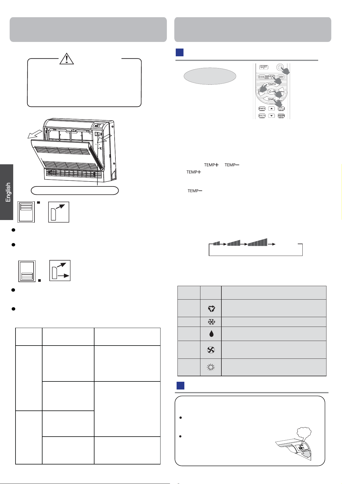
CAUTION
Before opening the front grille, be sure
to stop the operation and turn the
breaker OFF.
Do not touch the metal parts on the
inside of the indoor unit, as it may result
in injury.
Air outlet selection switch
Regardless of the operating mode or situation, air
blows from the upper air outlet.
Use this switch when you do not want air coming
out of the lower air outlet. (While sleeping etc..)
Operation
Base Operation
Remote controller
1. Unit start
Press ON/OFF on the remote controller, unit starts.
2. Select operation mode
COOL button:Cooling mode
HEAT button: Heating mode
DRY button: Dehumidify mode
3.Select temp.setting
Press
Every time the button is pressed, temp.setting
increase 1
rapidly
Every time the button is pressed, temp.setting
decrease
decrease rapidly
Select a desired temperature.
button
o
C,if kept depressed, it will increase
o
C,if kept depressed, it will
1
4.Fan speed selection
Press FAN button. For each press, fan speed
changes as
Remote controller:
Air conditioner is running under displayed fan speed.
When FAN is set to AUTO, the air conditioner
automatically adjusts the fan speed according to room
temperature.
follows:
LOW
MED HI
Display
circulated
AUTO
Air conditioner automatically decides the appropriate
blowing pattern depending on the operating mode
and situation.
During Dry and Fan mode, so that cold air does not
come into direct contact with people, air is blown upper
air outlet.
Operating
mode
Cool
mode
Heat
mode
Situation
When the room has
become fully cool.
At start of operation
or other times when
the room is not fully
cooled.
At times other than
below.
(Normal time.)
At start or when air
temperature is low.
Blowing pattern
So that air does not come
into direct contact with
people, air is blown
upper air outlet, room
temperature is equalised
Air is blown from the upper
and lower air outlets for
high speed cooling during
Cool mode, and for filling
the room with warm air
during Heat mode.
So that air does not come
into direct contact with
people.Air is blown upper
air outlet.
DRY
Remote
Controller
Note
Under the mode of auto operation, air conditioner will automatically
select Cool or Heat operation according to room temperature.
When FAN is set to AUTO the air conditioner automatically adjusts
the fan speed according to room temperature.
In DRY mode, when room temperature becomes lower than
temp.setting+2 C, unit will run intermittently at LOW speed
regardless of FAN setting.
In FAN operation mode,the unit will not operate in COOL or HEAT
mode but only in FAN mode, AUTO is not available in FAN mode.
And temp. setting is disabled In FAN mode, sleep operation is not
available.
In HEAT mode, warm air will blow out after a short period of the
time due to cold-draft prevention function.When FAN is set to
AUTO, the air conditioner automatically adjusts the fan speed
according to room temperature.
o
Operation
Mode
AUTO
COOL
FAN
HEAT
Emergency operation and test operation
Test operation:
Test operation switch is the same as emergency switch.
Use this switch in the test operation when the room
temperature is below 16 C, do not use it in the
normal operation.
Continue to press the test operation
switch for more than 5 seconds. After
you hear the "Pi" sound twice, release
your finger from the switch: the cooling
operation starts with the air flow speed "Hi".
o
Pi Pi
2

Operation
Emergency Operation:
Use this operation only when the
remote controller is defective or lost.
When the emergency operation
switch is pressed, the" Pi "sound is
heard once, which means the start
of this operation.
In this operation, the system
automatically selects the operation modes, cooling or
fan or heat, according to the room temperature.
When machine is running in emergency, the set value
of temperature and wind speed couldn't be altered;
meanwhile, it can't operate for dehumidifying or under
timing mode.
Pi
Air Flow Direction Adjustment
1.Adjusting the flap
Status display of air flow:
Pos.1
Pos.4
When SWING is selected, the flap swinging range depends
on the operation mode.(See the figure.)
Pos.2 Pos.3
Pos.5
COOL/DRY
HEAT
Pos.6
(Auto swing)
Timer On/Off On-Off Operation
1.After unit starts, select your desired operation mode.
2.Press TIMER button to change TIMER mode. Every
time the button is pressed, display changes as follows:
Remote controller:
0.5h
TIMER ON TIMER OFF TIMER ON-OFF
Then select your desired TIMER mode (TIMER ON or
TIMER OFF or TIMER ON-OFF). " "or " "will flash.
3.Press / button to set time.
Press the button for each time, setting time in the first
12 hours increased by 0.5 hour every time, after 12
hours,increased by 1 hour every time.
Press the button for each time, settiing time in the first
12 hours decreased by 0.5 hour every time, after 12
hours,decreased by 1 hour every time.
It can be adjusted within 24 hours.
4.Confirm timer setting
After adjust the time,press button and confirm the
time ON or OFF button will not flash any more.
5.Cancel timer setting
Press the timer button by times until the time display
eliminated.
0.5h 0.5h
0.5h
TIMER OFF-ON
BLANK
2.Left and right air flow adjustment (manual)
Move the vertical blade by a knob on air conditioner
to adjust left and right direction.
Cautions:
Do not try to adjust the flap by hand.
When adjusting by hand, the mechanism may not operate properly or condensation may drip from air outlets.
When adjusting the flap by hand, turn off the unit, and use
the remote controller to restart the unit.
When adjusting the flap by hand,turn off the unit.
When humidity is high,condensate water might occur
at air outlet if all vertical louvers are adjusted to left or
right.
It is advisable not to keep horizontal flap at downward
position for a long time in COOLor DRY mode ,
otherwise, condensate water might occur.
Note:
When restart after remote turning off, the remote
controller will automatically memorize the previous
set swing position.
Hints:
After replacing batteries or a power failure happens, time
setting should be reset.
According to the Time setting sequence of TIMER ON or
TIMER OFF, either Start-Stop or Stop-Start can be achieved.
TIMER On/Off Operation
Confirming your setting
After setting correct time, press button to confirm
" "or" "on the remote controller stops flashing.
Time displayed: Unit starts or stops at x hour.
Hints:
After replacing batteries or a power failure happens, time
setting should be reset. Remote controller possesses
memory function, when use TIMER mode next time, just
press button after mode selecting if time setting is
the same as previous one.
3

Operation
Sleep Operation
Press button to enter additional options, when
cycle display to , will flash. And then press
enter to sleep function.
Operation Mode
1. In COOL,DRY mode
1 hours after SLEEP mode starts,temp.will become
higher than temp.setting.After another 1 hours,temp.rises
O
C
by 1 futher.The unit will run for further
6 hours then stops
Temp. is higher than temp.setting so that room temperature
won’t be too low for your sleep.
SLEEP operation starts SLEEP operation stops
Approx.6hrs
Rises 1
Rises 1OC
O
C
Unit stop
1 hr
1 hr
Temp.setting
In COOL, DRY mode
In HEAT mode
2.
1 hours after SLEEP mode starts,temp will become 2
lower than temp.setting.After another 1 hours,temp
decrease by 2
by 1 futher.The unit will run for further 3 hours then
rises
O
C futher.After more another 3 hours,temp.
O
C
stops.Temp.is lower than temp. setting so that room
temperature won’t be
Temp.setting
SLEEP
operation starts
In AUTO mode
3.
too high for your sleep.
1 hr
Decreases 2OC
1 hr
Decreases 2
3 hrs
In HEAT mode
Unit stop
O
C
3 hrs
Rises 1OC
SLEEP
operation stops
The unit operaters in corresponding sleep mode
adapted to the automatically selected operation
4. In FAN mode
It has no SLEEP function.
5.Set the wind speed change when sleeping
If the wind speed is high or middle before setting for the
sleep, set for lowing the wind speed after sleeping.
If it is low wind, no change.
O
C
1
O
C
mode.
Note
When TIMER function is set, the sleeping function can’t be
if user resets
p
set up .After the sleeping function is set u
,
TIMER function, the sleeping function will be cancelled; the
machine will be in the state of
timing-on.
POWER/QUIET Operation
(1)
POWER Operation
When you need rapid heating or cooling, you can use this function.
Press button to enter additional options, when cycle
display to , will flash,and then press ,enter to
power function. When cancel the function, please enter
additional options again and to cancel power function.
(2)
QUIET Operation
You can use this function when silence is needed for rest or reading.
Press QUIET button, the remote controller will show ,
and then achieve to the quiet function. Press again this
QUIET button , the quiet function will be cancelled.
Note ˖
During POWER operation, in rapid HEAT or COOL mode ,
the room will show inhomogeneous temperature distribution.
Long period QUIET operation will cause effect of not too
cool or not too warm.
EUROPEAN REGULATIONS
CONFORMITY FOR THE MODELS
CE
All the products are in conformity with the following
European provision:
- Low Voltage Directive 73/23/EEC
- Low Voltage Directive 2006/95/EC
-Electomagnetic CompatibilitY 89/336/EEC
-Electomagnetic CompatibilitY 2004/108/EC
ROHS
The products are fulfilled with the requirements in the
directive 2002/95/EEC of the European parliament and of
council on the Restriction of the use of Certain Hazardous
Substances in Electrical and Electronic Equipment (EU
RoHS Directive)
WEEE
In accordance with the directive 2002/96/CE of the European
parliament, herewith we inform the consumer about the dis-
posal requirements of the electrical and electronic products.
DISPOSAL REQUIREMENTS:
Your air conditioning product is marked with this
symbol.This means that electrical and electronic
products shall not be mixed with unsorted
household waste. Do not try to dismantle the
system yourself : the dismantling of the air
conditioning system,treatment of the refrigerant, of oil and of
other part must be done by a qualified installer in
with relevant local and national legislation. Air conditioners
must be treated at a specialized treatment facility for reuse,
recycling and recovery. By ensuring this product is disposed
of correctly, you will help to prevent potential negative consequences for the environment and humen health. Please
contact the installer or local authority for more information.
Battery must be removed from the remote controller and disposed of separately in accordance with relevant local and
nationl legislation.
accordance
4
Indoor Unit Installaion
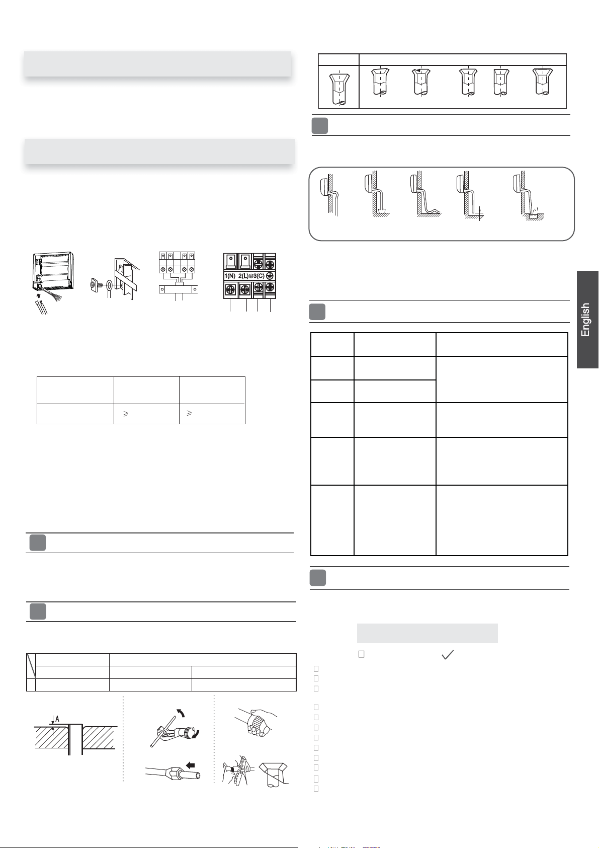
Necessary Tools for Installation
Torque wrench
Driverƽ
Nipperƽ
Hacksawƽ
Hole core drillƽ
Spanner(17,19 and 26mm)ƽ
Gas leakage detector orƽ
soap-and-water solution
ƽ
(17mm,22mm,26mm)
Pipe cutterƽ
Flaring toolƽ
Knifeƽ
Measuring tapeƽ
Reamerƽ
Selection of Installation Place
ƽ
Place, robust not causing vibration, where the body can
be
supported suf ficiently.
Place, not affected by heat or steam generated in the
ƽ
vicinity,
Place, possible to drain easily, where piping can be
ƽ
connectedwiththeoutdoorunit.
Place,wherecoldaircanbespreadin a roomentirely.
ƽ
ƽ
Place, nearby a power receptacle, with enough space
around.
Place where the distance of more than lm from
ƽ
televisions,
fluorescent lamps
ƽ
In the case of fixing the remote controller on a wall,
place
fluore
where inlet and outlet of the
radios, wireless apparatuses
can be
left.
where the indoor unit can
scent
in the room are lightened.
lamps
unit are not disturbed.
a
nd
receivesignalswhenthe
Power Source
ƽ
Before inserting power
without
ƽ
The power
nameplate.
Install an exclusive branch circuit of the power.
ƽ
A receptacle shall be set up in a distance where the power
ƽ
cable
fail.
supply is the same as the
reached.
be
can
intoreceptacle,checkthevoltage
corresponding
Donotextendthecablebycuttingit.
Accessory Parts
Remote controller (1)
R-03 dry battery (2)
Mounting plate (1)
Drain hose (1)
Plastic cap (4)
Ø4X25 Screw
Air purifying filter(Optional) (1)
(4)
Selection of Pipe
FOR 09K 12K
FOR 18K
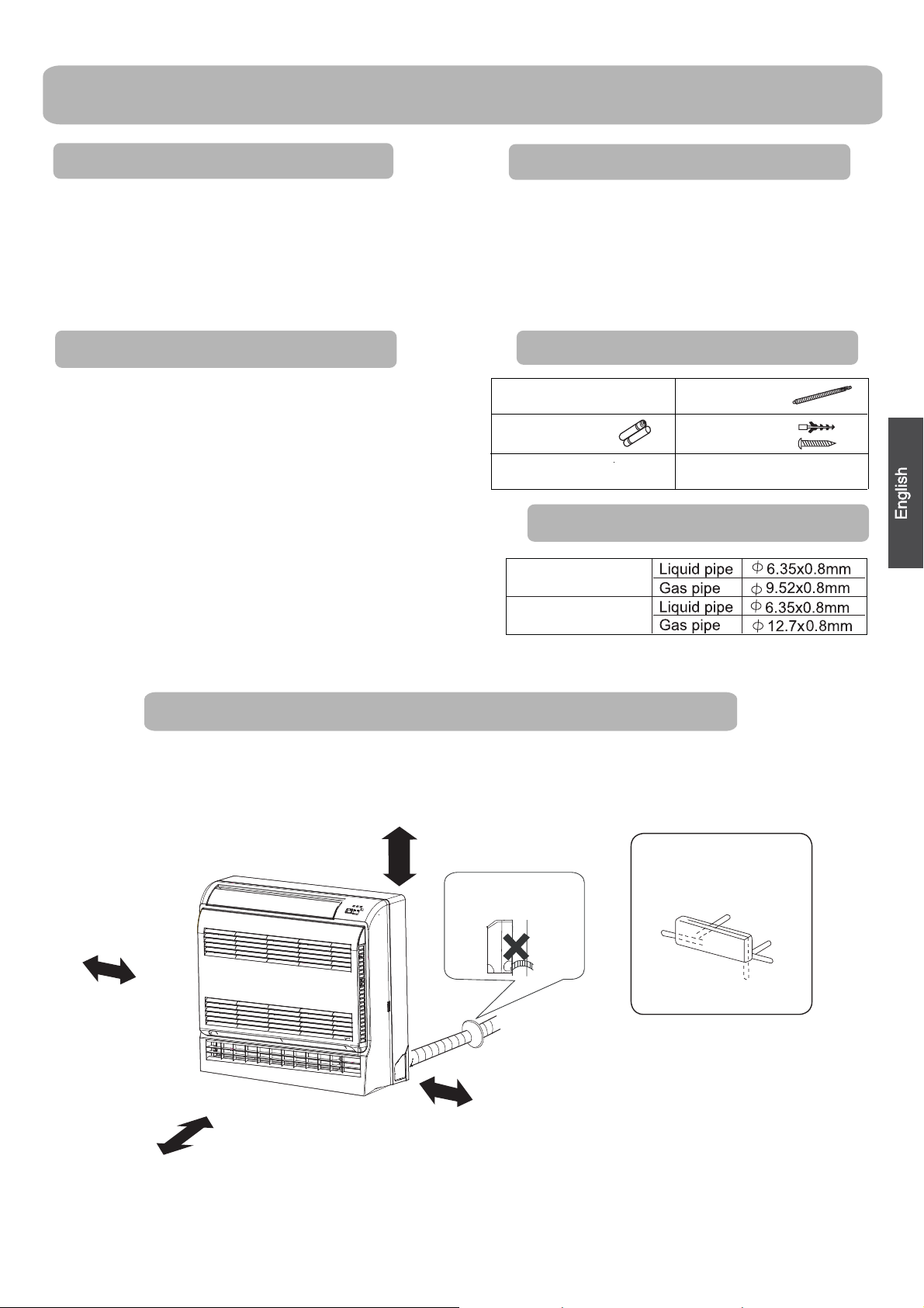
Drawing for the installation of indoor units
ThemodelsadoptHFCfreerefrigerantR410A
more than
more than cm
10cm
more than 60 cm
20
Attention must be paid to
the rising up of drain hose
more than 10cm
Arrangement of piping
directions
Rear left
Left
Below
Rear
right
Right
5
Indoor Unit Installation
Making a Hole on the Wall and Fitting the Piping Hole
Cover
Make a hole of 70 mm in diameter, slightly descending to outside the
ƽ
wall
Install piping hole cover and seal it off with putty after installation
ƽ
Wall hole
Ø70mm
Indoor side
(Section of wall hole)
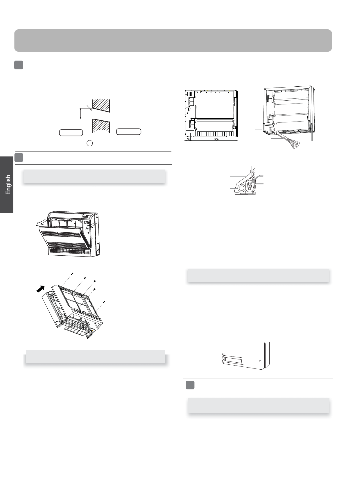
Installation of the Indoor Unit
Thickness of wall
Piping hole pipe
G
Outdoor side
Removal of Front Grille
Hold the front panel by the tabs on the both sides and lift it until it
ƽ
stops with a click.
Loosen the marked five
ƽ
screws and open the grille
3. Coat the flaring seal face with refrigerant oil and connect pipes.
Cover the connection part with heat insulation materials closely,
and
make sure
ƽ
Indoor/outdoor electric cable and drain hose must be bound with
efrigerant
fixing with adhesive tape
Lid for right
piping
Fix with adhesive
tape
Indoor/outdoor electric cable
Heat insulation
material
Drain hose
piping by protecting tape.
Piping
Pipe supporting
plate
Lid for left piping
[ Other direction piping ]
Cut away, with a nipper, the lid for piping according to the piping
ƽ
direction
hole.Whenbending,be
ƽ
Connect beforehand the indoor/outdoor electric cable,
pull out the
specially.
then bend the pipe according to theposition of wall
and
careful not to crash
connected to the heat insulation of connecting part
pipes.
and then
Drawing of pipe
[ Rear piping ]
Drawpipesandthedrainhose,thenfastenthemwiththeadhesive
ƽ
tape
[Left·Left-rear piping ]
ƽ
In case of left side piping, cut away, with a nipper, the lid for left
piping.
ƽ
In case of left-rear piping, bend the pipes according to the piping
direction to
heat
1. Insert the drain hose into the dent of heat insulation materials of
indoor
2. Insert the indoor/outdoor electric cable from backside of indoor
unit,
the mark of hole for left-rear piping which is marked on
insulation materials.
unit.
andpullit
out on the front side, then connect them.
Fixing the indoor unit body
Remove the front panel,then use two fastening screws to fix
ƽ
the unit on the floor. As the figure shown.
Once refrigerant piping and drain piping connections are
ƽ
complete,fill the gap of the through hole with putty.Attach the
front panel and front grille in their orginal positions once
all connections are complete.
Connecting the indoor/outdoor Electric Cable
Removingthewiringcover
R
emove terminal cover at top right corner of indoor unit,and then
ƽ
off wiring cover by removing its screws.
take
6
When connecting the cable after installing the indoor unit
Correct Incorrect
1. Insert from outside the room cable into left side of the wall
hole,inwhichthepipehasalreadyexisted.
2.Pulloutthecableonthefrontside,andconnectthecable
making a loop.
When connecting the cable before installing the indoor unit
Insertthecablefromtheback
ƽ
ƽ
Loosen the screws and insert
tighten the screws.
Pull the cable slightly to
ƽ
and
tightened.
After the cable connection,
ƽ
wiring cover.
side of the u nit, then pull it out
the cable ends fully into
make sure the cables have
never fail to fasten the connected cable with the
been properly inserted
on the front side.
terminal block, then
Indoor unit
To Outdoor unit
Note:
When connecting the cable, confirm the terminal number of indoor and
outdoor units carefully. If wiring is not correct, proper operation can not
becarriedoutandwillcausedefect.
Model
Connecting wiring
1.Ifthesupplycordisdamaged,itmustbereplacedbythemanufacturerorits
service agent or a similar qualified person. The type of connecting wire is
H05RN-F
2. If the fuse on PC board is broken please change it with the
T.3.15A/250VAC (Indoor).
3.Thewiringmethodshouldbeinlinewiththelocalwiringstandard.
4.Afterinstallation,thepowerplugshouldbeeasilyreached.
5. A breakershouldbeincorporatedintofixedwiring.Thebreakershouldbe
all-pole
than 3mm.
ƽ
The power source must be exclusively used for air
ƽ
In the case of installing an air conditioner in a moist place,
install
ƽ
For installation in other places, use a circuit breaker as far
or H07RN-F.
switch and the distance between its two c
Power Source Installation
rth leakage breaker.
an ea
CuttingandFlaringWorkofPiping
AF09AS1ERA
AF12AS1ERA
4G0.75mm
2
AF18AS1ERA
4G0.75mm
2
type of
ontactsshouldbenotless
conditioner.
please
as possible.
Lean
Damage of flare Partial Too outside
On Drainage
Pleaseinstallthedrainhosesoastobedownwardslopewithoutfail.
ƽ
Please don’t do the drainage as shown below.
ƽ
It becomes
high midway.
Pleasepourwaterinthedrainpan of theindoorunit,and
ƽ
that
In case that the attached drain hose is in a room, please
ƽ
heat
Code
indication
E1
E2
E4
The end is immersedinwater.
drainage
insulation
is carried out surely to outdoor.
to
On Drainage
Trouble description
Room temperature
sensor failure
Heat-exchange
sensor failure
Indoor EEPROM
error
It waves.
it without fail.
Communication
E7
fault between
indoor and outdoor
units
Crack
Less than
5cm
The gap with the
ground is too small.
Thereisthebad
smell from a ditch
confirm
apply
Analyze and diagnose
Faulty connector connection;
Faulty thermistor;
Faulty PCB;
Faulty EEPROM data;
Faulty EEPROM;
Faulty PCB;
Indoor unit- outdoor unit signal
transmission error due to wiring
error;
Faulty PCB;
Operation halt due to breaking
of wire inside the fan motor;
E14
Indoor fan motor
malfunction
Operation halt due to breaking
of the fan motor lead wires;
Detection error due to faulty
indoor unit PCB;
Check for Installation and Test Run
Please kindly explain to our customers how to
Ƶ
operate
through the instruction manual.
Pipecuttingiscarriedoutwith a pipecutterandbursmust beremoved.
ƽ
Afterinsertingtheflarenut,flaring workiscarriedout.
ƽ
FlaretoolforR410A Conventionalflaretool
Clutch-type clutch-type(Rigid-type) Wing-nut type (Imperial-type)
A 0~0.5mm 1.0~1.5mm 1.5~2.0mm
Flare tooling die
1.Cut pipe
3.Inserttheflarenut
2.Remove burs
4.Flare pipe
Check Items for Test Run
Put check mark
Gasleakfrompipeconnecting?
Heat insulation of pipe connecting?
Are the connecting wirings of indoor and outdoor firmly
inserted to the terminal block?
Istheconnectingwiring of indoorandoutdoorfirmlyfixed?
Is drainage securely carried out?
Is the earth line securely connected?
Istheindoorunitsecurelyfixed?
Ispowersourcevoltageabidedbythecode?
Is there any noise?
Is the lamp normally lighting?
Arecoolingandheating(wheninheatpump)performednormally?
Is the operation of room temperature regulator normal?
in boxes
7
Maintenance
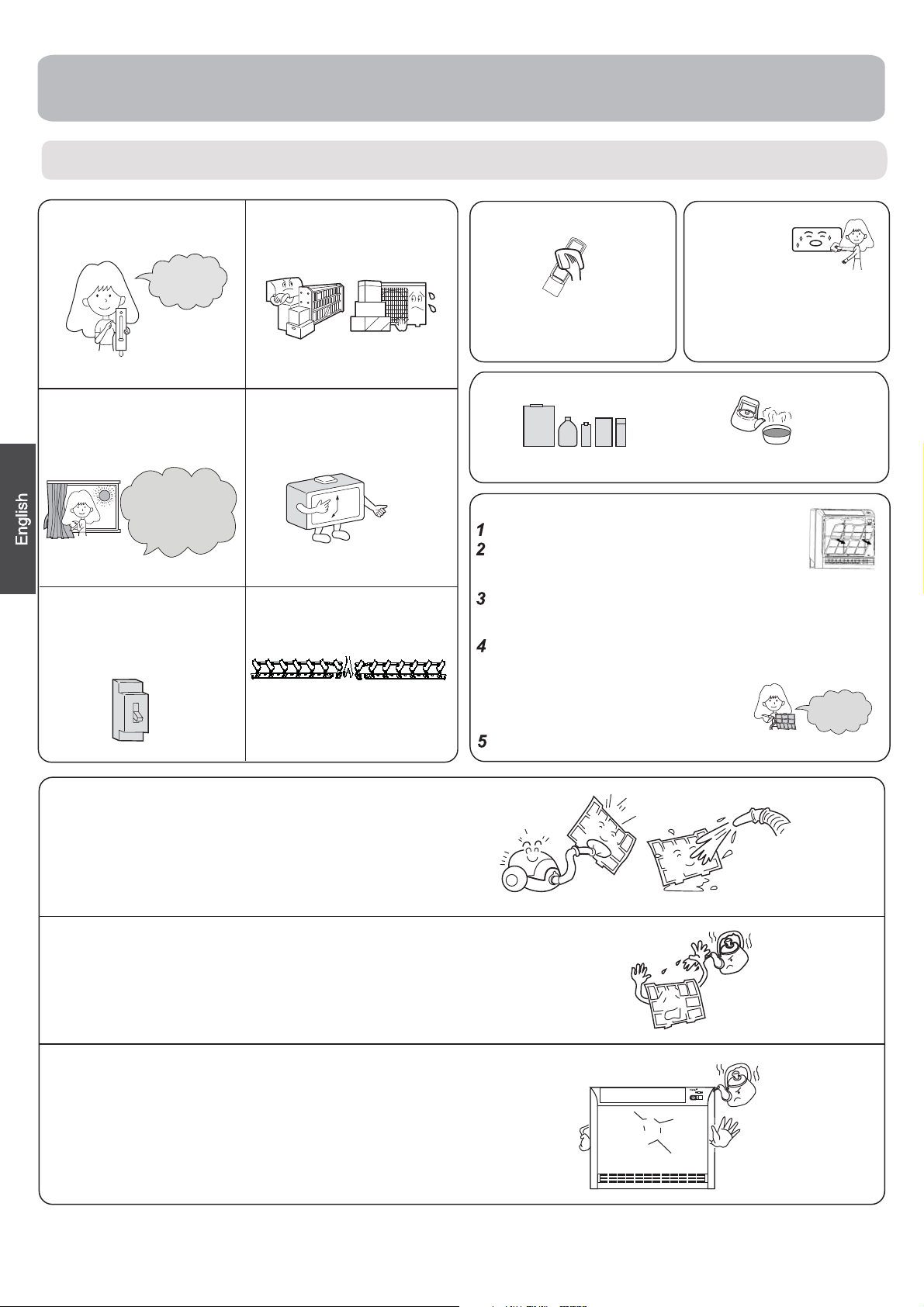
For Smart Use of The Air Conditioner
Setting of proper room
temperature
Proper
temperature
Close doors and windows
during operation
During cooling
operation prevent
the penetration of
direct sunlight with
curtain or blind
If the unit is not to be used
for a long time, turn off the
power supply main switch.
OFF
Do not block the air inlet
or outlet
Use the timer effectively
Use the louvers effectively
Remote Controller
Do not usewater, wipe the controller
with a dry cloth.Do not use glass
cleaner or chemical cloth.
Indoor Body
wipe the air conditioner by using a
soft and dry cloth.For serious stains,
use a neutral detergent diluted with
water. Wring the water out of the
cloth before wiping,then wipe off
the detergent completely.
Do not use the following for cleaning
Gasoline,benzine,thinner or cleanser
may damage the coating of the unit.
Hot water over 40 C(104 F) may
cause discoloring or deformation.
O
Air Filter cleaning
Open the inlet grille by pulling it upward.
Remove the filter.
Push up the filter's center tab slightly until it is
released from the stopper, and remove the filter downward.
Clean the filter.
Use a vacuum cleaner to remove dust, or wash the filter with
water. After washing, dry the filter completely in the shade.
Attach the filter.
Attach the filter correctly so that the “FRONT” indication is facing to
the front. Make sure that the filter is completely
fixed behind the stopper. If the right and left
filters are not attached correctly, that may
cause defects.
Close the inlet grille.
Once every
two weeks
O
Clean the filter
Use water or vacuum cleaner to remove dust. If it is too dirt,
clean with detergent or neutral soap water.
Rinsing with fresh water, dry the filter and re-assemble.
Caution
Do not wash filter in hot water above 40
Do carefully wipe the filter.
o
C,which will damage the filter.
Clean the indoor(outdoor) unit
Clean with warm cloth or neutral detergent, then wipe away moisture
with dry cloth. Do not use too hot water(above 40 C), which will cause
discoloration or deformation. Do not use pesticide or other chemical
detergents.
o
8

Cautions
WARNING
Please call Sales/Service Shop for the Installation.
Do not attempt to install the air conditioner by yourself because improper works may cause
electric shock, fire, water leakage.
WARNING
When abnormality such as burnt-small found,
immediately stop the operation button and
contact sales shop.
OFF
Connect power supply cord
to the outlet completely
STRICT
ENFORCEMENT
Do not use power supply
cord in a bundle.
STRICT
ENFORCEMENT
Use the proper voltage
Take care not to damage
the power supply cord.
Use an exclusive
power source
with a circuit
breaker
STRICT
ENFORCEMENT
Check proper installation of the
drainage securely
STRICT
ENFORCEMENT
1.Do not use power supply cord extended
or connected in halfway
2.
Do not install in the place where there is any
possibility of inflammable gas leakage around the unit.
3.Do not get the unit exposed
to vapor or oil steam.
PROHIBITION
Do not insert objects into the air inlet or outlet.
PROHIBITION
Do not start or stop the
operation by disconnecting
the power supply cord
and so on.
PROHIBITION
Do not use for the purpose of storage of
food, art work, precise equipment,
breeding, or cultivation.
PROHIBITION
Do not install the unit near a fireplace
or other heating apparatus.
PROHIBITION
Do not place animals or plants in
the direct path of the air flow
Do not channel the air flow directly
at people, especially at infants or
the aged.
PROHIBITION
Do not try to repair or
reconstruct by yourself.
PROHIBITION
CAUTION
Take fresh air occasionally especially
when gas appliance is running at the
same time.
STRICT
ENFORCEMENT
Check good condition of the
installation stand
PROHIBITION
Do not place any objects on or
climb on the unit.
PROHIBITION
Connect the earth
cable.
earthing
Do not operate the switch with
wet hand.
PROHIBITION
Do not pour water onto the unit
for cleaning
PROHIBITION
Do not place flower vase or water
containers on the top of the unit.
PROHIBITION
PROHIBITION
PROHIBITION
9
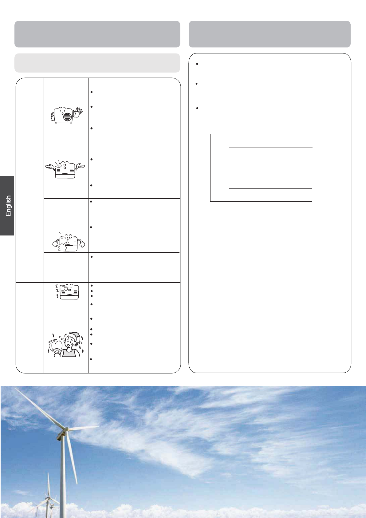
Trouble shooting
Cautions
Before asking for service, check the following
first.
Cause or check points
When unit is stopped, it won't restart
immediately until 3 minutes have
elapsed to protect the system.
When the electric plug is pulled out
and reinserted, the protection circuit
will work for 3 minutes to protect the
air conditioner.
During unit operation or at stop,
a swishing or gurgling noise may
be heard.At first 2-3 minutes after
unit start, this noise is more noticeable.
(This noise is generated by
refrigerant flowing in the system.)
During unit operation, a cracking
noise may be heard.This noise is
generated by the casing expanding
or shrinking because of
temperature changes.
Should there be a big noise from
air flow in unit operation, air
filter may be too dirty.
This is because the system
circulates smells from the interior
air such as the smell of furniture,
paint, cigarettes.
During COOL or DRY operation,
indoor unit may blow out mist.
This is due to the sudden cooling
of indoor air.
In DRY mode, when room temperature
becomes lower than temp.
setting+2
intermittently at LOW speed
regardless of FAN setting.
Is power plug inserted?
Is there a power failure?
Is fuse blownout?
Is the air filter dirty?
Normally it should be cleaned
every 15 days.
Are there any obstacles before
inlet and outlet?
Is temperature set correctly?
Are there some doors or
windows left open?
Is there any direct sunlight
through the window during the
cooling operation?(Use curtain)
Are there too much heat sources
or too many people in the room
during cooling operation?
o
C,unit will run
Normal
Performance
inspection
Multiple
check
Phenomenon
The system
does not restart
immediately.
Noise is heard
Smells are
generated.
Mist or steam are
blown out.
In dry mode,
speed can’t be
changed.
Poor cooling
fan
Do not obstruct or cover the ventilation
conditoner.Do not put fingers
inlet/outlet and
Do not allow children to play with the air
case should children be
swing louver.
or any other things into the
allowed to sit on the outdoor unit.
grille of the air
conditioner
Specifications
The refrigerating circuit is leak-proo f.
The machine is adaptive in following
1.Applicable ambient temperature range:
Indoor
Cooling
Outdoor
Indoor
Heating
Outdoor
Outdoor
(INVERTER)
2. If the power supply cord is damaged, it
manufacturer
3. If the fuse of indoor unit on PC board is
it with the type of
broken,change it with the type of
4. The wiring method should be in line with
5. After installation, the power plug should
6. The waste battery should be disposed
7. The appliance is not intended for use
persons
8.Young children should be supervised
the appliance.
with
9. Please employ the proper power plug,
cord.
10. A breaker should be incorporated into
should be
should be not less than 3mm.
11 .The power plug and connecting cable
attestation.
12.In order to protect the units, please turn
30 seconds
or its service agent or a similar
without supervision.
all-pole switch and the distance
later, cutting off the power.
Maximum:D.B/W.B
Minimum:D.B/W.B
Maximum:D.B/W.B
Minimum:
Maximum:D.B
Minimum:
Maximum:D.B/W.B
Minimum:D.B/W.B
Maximum:D.B/W.B
Minimum:D.B
T. 3.15A/ 250V
D.B
D.B
must be replaced
broken,please
. If the fuse of
T.25A/250V
the local wiring
be easily reached.
properly.
by young children or
to ensure that th
which fit into the
fixed wiring. The
between
must have
off the A/C first,
.In no
situation
32oC/23oC
o
21
C/15oC
o
46
C/26oC
o
18
C
o
C
27
0oC
o
C/18oC
24
o
-
C/-8oC
7
o
C/18oC
24
o
C
-15
qualified
outdoor
p
its two contacts
acquired the local
by the
person.
change
unit is
standard.
infirm
ey
do not play
ower supply
breaker
and at least
Haier Group
Address:No.1 Haier Road,Hi-tech Zone,Qingdao 266101 P.R.China
Contacts: TEL +86-532-8893-6943;FAX +86-532-8893-1010
Website: www.haier.com
10

Componentes y funciones
Unidad interior
Paleta vertical
(permite ajustar la
dirección del flujo de aire
hacia la izquierda y hacia
la derecha; interior)
Salida de aire
Rejilla de entrada
de aire
Paleta vertical
Deflector horizontal
(permite
ajustar la dirección del flujo de
aire hacia arriba y hacia abajo
no lo ajuste manualmente)
Indicador luminoso
Interruptor de
emergencia
Filtro purificador de aire
Salida de aire
(interior)
Recuerde que la ilustración anterior podría no reflejar
fielmente el producto adquirido y debe utilizarse únicamente como referencia.
ALIMENTACIÓN
INTERRUPTOR DE EMERGENCIA
Interruptor de
emergencia
TEMPORI-
ZADOR
•• Botón ENCENDIDO/APAGADO
Pulse este botón para iniciar el fun-
•
FUNCIONA
MIENTO
-
INTERRUPTOR DE
EMERGENCIA Y DE
PRUEBA
Receptor de señal
cionamiento; púlselo de nuevo para
detener el funcionamiento.
Si el funcionamiento se establece en
•
AUTOMÁTICO, el flujo de aire se establece en ventilador AUTOMÁTICO.
Se utiliza cuando el mando a distan-
•
cia en esta disponible.
Receptor de
señal
Unidad exterior
SALIDA DE AIRE
ELÉCTRICO
ENTRADA DE AIRE
Cuando se recibe una señal, se
•
emite un sonido de recepción.
TUBOS DE CONEXIÓN Y CABLEADO
MANGUITO DE DRENAJE
4
Recuerde que la ilustración anterior podría no reflejar
fielmente el producto adquirido y debe utilizarse únicamente
como referencia.
Mando a distancia
1
2
3
4
5
9
10
11
12
13
14
15
16
17
1. Indicador de modo
Modo de
funcionamiento
Mando a
distancia
2. Indicador de envío de señal
3. Indicador de OSCILACIÓN
4. Indicador de VELOCIDAD DE
VENTILADOR
BAJA MEDIA ALTA AUTOMÁTICO
5. Indicador de BLOQUEO
6. Indicador
TEMPORIZADOR DE
APAGADO
TEMPORIZADOR DE
ENCENDIDO
7. Indicador de TEMPERATURA
La función Saludable no está disponible para algunas unidades.
Instalación de las pilas
REFRIGERACIÓN SECO CALEFACCIÓN VENTILADOR
AUTOMÁTICO
Visualización
circular
1
2
8. Indicador de funciones adicionales
6
Modo de
SILENCIO SUELO
funcionamiento
Mando a
distancia
7
9. Botón SILENCIO
10. Botón CALOR
11. Botón FRÍO
12. Botón AUTOMÁTICO
8
13. Botón VENTILADOR
14. Botón TEMPORIZADOR
18
15. Botón SALUDABLE
16. Botón BLOQUEAR
19
Se utiliza para bloquear los botones y
la pantalla LCD.
20
17. Botón LUZ
Controla la activación y desactivación
de la iluminación del panel de
21
indicadores LED de la unidad interior.
18. Botón ENCENDIDO / APAGADO
22
19. Botón SECO
20. Botón TEMPERATURA
23
21. Botón OSCILACIÓN
22. Botón HORA
24
23. Botón FUNCIÓN ADICIONAL
Función: Dirección del aire
25
Posición de flujo de aire saludable
---
Posición de flujo de aire
1
saludable 2
original de la aleta
horizontal
símbolo de calefacción mostrado
simultáneamente
Calefacción eléctrica
eléctrica Potencia
conversión Fahrenheit/Celsius
24. Botón CANCELAR/CONFIRMAR
Función: establecer y cancelar el
temporizador y otras funciones
adicionales.
25. Botón RESTABLECER
Si el mando a distancia presenta
alguna anomalía, introduzca un objeto
puntiagudo a través del orificio para
pulsar este botón y restablecer el
mando a distancia.
---
Ayuda con calor
eléctrico
---
Restablecer la posición
---
Flujo de aire
---
Dormir
---
---
Modo de
---
Calefacción
Jardín A-B
Extraiga la tapa de las pilas;
En la figura se muestra el modo
de carga de las pilas. 2 pilas
R-03, botón reinicio (botella);
Asegúrese de respetar los signos
3
"+" y "-";
Instale las pilas y vuelva a colocar de nuevo la tapa.
4
Nota:
La distancia entre el cabezal de transmisión de la señal y el orificio del
receptor debe ser de unos 7 m sin obstáculos.
Si se instalan lámparas fluorescentes o se utilizan teléfonos inalámbricos
en la sala, el receptor podría resultar perturbado al recibir las señales, por
lo que la distancia hasta la unidad interior deberá ser menor.
Si se activan todos los indicadores de la pantalla o no es posible
visualizarlos correctamente durante el uso, es señal de que las pilas se han
agotado. Por favor, cambie las pilas.
Si el mando a distancia no funciona normalmente durante su uso,
extraiga las pilas y vuelva a instalarlas pasados unos minutos.
Sugerencia:
Extraiga las pilas si no tiene intención de utilizar la unidad durante un
periodo largo de tiempo. Si observa alguna pantalla extraña después de
extraer las pilas deberá pulsar el botón Restablecer.
SALUDABLE INTENSO
---
10 y
---
11
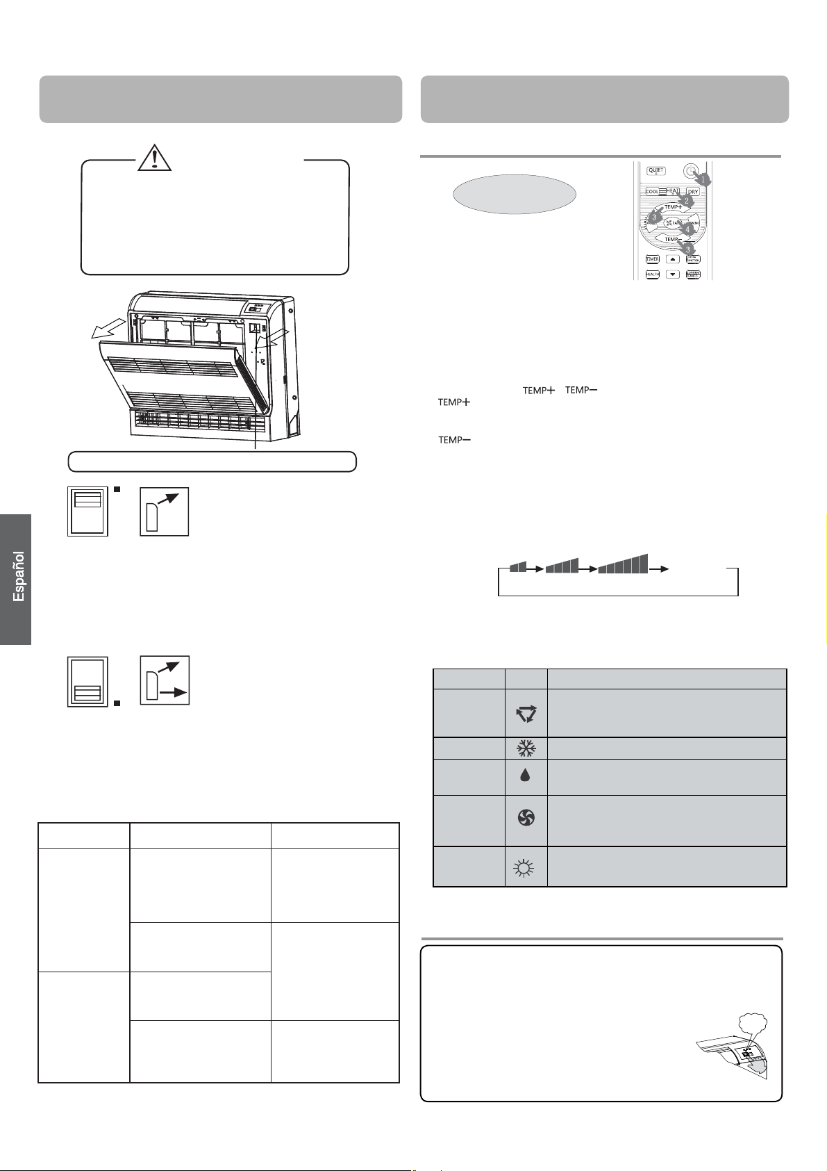
Componentes y funciones
PRECAUCIÓN
Antes de abrir la rejilla frontal, asegúrese
detener el funcionamiento de la máquina
y de DESCONECTAR el interruptor.
No toque las partes metálicas internas de
la unidad interior, ya que se podrían producir lesiones personales.
1. Arranque de la unidad
2. Selección del modo de funcionamiento
3. Selección de la configuración de temperatura
Conmutador de selección de la salida de aire
4. Selección de la velocidad del ventilador
•Independientemente del modo de funcionamiento
o la situación, el aire fluye desde la salida de aire
superior.
•Utilice este conmutador cuando no desee que salga
aire de la salida de aire inferior. (por ejemplo mientras duerme).
• El aparato de aire acondicionado decide el patrón
de emisión de aire apropiado en función del modo
de funcionamiento y la situación.
• En los modos Seco y Ventilador, en los que el aire
frío no entra en contacto con las personas, el aire
se emite desde la salida de aire superior.
Modo de
funcionamiento
Modo Refrigeración
Modo Calefacción
12
Situación
Cuando la habitación se ha
refrigerado completamente.
Al iniciarse el modo de
funcionamiento u otras veces
en las que la habitación no está
totalmente refrigerada.
Cuando no se da ninguna de las
situaciones anteriores. (Período
normal.)
Durante el inicio o cuando la
temperatura de aire es baja.
Patrón de emisión de aire
De esta forma, el aire no
entra en contacto directo con
las personas, se emite desde
la salida de aire superior y
la temperatura de la sala se
iguala.
El aire se emite desde las
salidas de aire superior
e inferior para enfriar
la habitación a alta
velocidad durante el modo
Refrigeración, y para llenar la
habitación con aire caliente
durante el modo Calefacción.
De esta forma, el aire no
entra en contacto con las
personas.Air is El aire se
emite desde la salida de aire
superior.
Funcionamiento
Funcionamiento básico
Mando a distancia
Pulse el botón de ENCENDIDO / APAGADO en el mando a
distancia para arrancar la unidad.
Botón FRÍO: modo de refrigeración
Botón CALOR: modo de calefacción
Botón SECO: modo de deshumidificación
Pulse el botón / .
Cada vez que pulse este botón, la configuración de
temperatura aumentará en 1 ºC. Si mantiene el botón
pulsado, la temperatura aumentará rápidamente.
Cada vez que pulse este botón, la configuración de
temperatura bajará 1 ºC. Si mantiene el botón pulsado,
la temperatura bajará rápidamente.
Seleccione la temperatura que desee.
Pulse el botón VENTILADOR. Cada vez que pulse el botón,
la velocidad del ventilador
ilustrado a continuación:
Mando a distancia:
BAJA MEDIA ALTA AUTOMÁTICO
El aparato de aire acondicionado funciona según la velocidad
de ventilador indicada.
Si el VENTILADOR se configura en el modo AUTOMÁTICO,
el aparato de aire acondicionado ajustará automáticamente la
velocidad del mismo según la temperatura de la habitación.
Modo de
funcionamiento
AUTOMÁTICO
REFRIGERACIÓN
SECO
VENTILADOR
CALEFACCIÓN
Funcionamiento en modo de emer
Control
remoto
gencia y en modo de prueba
Funcionamiento en modo de prueba:
El interruptor de funcionamiento en modo de prueba es
similar al interruptor de emergencia.
Utilice este interruptor en el modo de funcionamiento de prueba
•
si la temperatura de la habitación es inferior a 16ºC.
No lo utilice en el modo de funcionamiento normal.
•
Continúe presionando el interruptor del modo de
funcionamiento de prueba durante más de 5
segundos. Suelte el dedo del interruptor cuando
escuche dos veces el sonido "Pi": el modo de
refrigeración se iniciará con el flujo de aire a velocidad "Alta".
cambiará de acuerdo con el ciclo
Visualización
circular
Nota
En el modo de funcionamiento automático, el aparato de aire
acondicionado seleccionará automáticamente el modo de
Refrigeración o Calefacción según la temperatura de la habitación.
Si el VENTILADOR está configurado en el modo AUTOMÁTICO,
el aparato de aire acondicionado ajustará automáticamente su
velocidad según la temperatura de la habitación.
En el modo SECO, si la temperatura de la habitación desciende por
debajo de la temperatura configurada + 2°C, la unidad funcionará
de forma intermitente a BAJA velocidad, independientemente de la
configuración de VENTILADOR.
En el modo VENTILADOR, la unidad no funcionará en los modos
de REFRIGERACIÓN o CALEFACCIÓN, sino únicamente en el
modo VENTILADOR, durante el cual tampoco estará disponible
el modo AUTOMÁTICO. Además, la función de configuración
de temperatura permanece deshabilitada en el modo
VENTILADOR y la función SUEÑO no está disponible.
En el modo CALEFACCIÓN, el aire cálido se expulsa después de un
corto periodo de tiempo gracias a la función de prevención de frío.
Si el VENTILADOR se configura en el modo AUTOMÁTICO,
el aparato de aire acondicionado ajustará automáticamente la
velocidad del mismo según la temperatura de la habitación.
Pi Pi
-
 Loading...