


AS09GS2ERA
Please read this operation manual before using the air conditioner.
●
Keep this operation manual for future reference.
SPLITTYPEROOMAIRCONDITIONER
OPERATION MANUAL
0010535381
AS07GS2ERA
AS09GS2ERA
AS12GS2ERA
AS18GS2ERA
AS24GS2ERA
9
1
2
8
5
Contents
Contenido
11
12
15
18
19
Indice
21
22
25
28
29
Table des matières
31
39
32
35
38
PARTS AND FUNCTIONS
OPERATION
INDOOR UNIT INSTALLAION
MAINTENANCE
CAUTIONS
TROUBLE SHOOTING
10
INSTALACIÓN DE LA UNIDAD INTERIOR
MANTENIMIENTO
PRECAUCIONES
RESOLUCIÓN DE PROBLEMAS
PARTES Y FUNCIONES
FUNCIONAMIENTO
20
PARTI E FUNZIONI
FUNZIONAMENTO
INSTALLAZIONE UNITÀ INTERNA
MANUTENZIONE
AVVERTENZE
RISOLUZIONE DEI PROBLEMI
30
ÉLÉMENTS ET FONCTIONS
UTILISATION
INSTALLATION DE L'UNITÉ INTÉRIEURE
ENTRETIEN
MISES EN GARDE
DÉPANNAGE
40


Outdoor Unit
Loading of the battery
1
2
3
4
Parts and Functions
Indoor Unit
OUTLET
INLET
CONNECTING PIPING AND ELECTRICAL WIRING
DRAIN HOSE
Remote controller
Remove the battery cover;
Load the batteries as illustrated.
2 R-03 batteries, resetting key
(cylinder);
Be sure that the loading
is in line with th
e" + "/"-";
Load the battery,then put on the cover again.
The distance between the signal transmission head and the rece-
iver hole should be within 7m without any obstacle as well.
When electronic-started type fluorescent lamp or change- over
wireless telephone is installed in the
ver is apt to be disturbed in receiving
the signals,
so the distance to the indoor unit should be shorter.
type fluorescent lamp or
room, the recei
Note:
Full display or unclear display during operation indicates the
ries have been used up.
Please change batteries.
If the remote controller can't run normally during operation, please
reload several minutes later.
batte
remove the batteries and
Please be subject to the actual produce purchased the
above picture is just from your reference
4
Hint:
Remove the batteries in case won't be in use for a long period. If
there is any display after taking-out, just press reset key.
Please be subject to the actual produce purchased the
above picture is just from your reference
Display board
(adjust left and
ow)
Vertical blade
r
ight air fl
Air Purifying Filter
Inlet
(inside)
Emergency
Switch
Horizontal flap
(adjust up and down air flow
Don't adjust it manually)
Outlet
Inlet grille
Display board
1
4
2
3
5
Signal receiver hole
ON/OFF display
4
2
3
1
5
TIMER ON\OFF display
SLEEP display
Ambient temp.display
When receiving the remote
control signal, display the set
displayed and this room
time the room temperature is
temperature and in the rest
temperature is only for reference.
Note to the power failure resume:
press the sleep button ten times in five seconds
and enter function after hearing four sounds.And
press the sleep button ten times within five
seconds and leave this function after hearing
TIMER ON-OFF display
COOL\HEAT\Dry\AUTO display
two sounds.
1. Mode display
2. Signal sending display
4. FAN SPEED display
5. LOCK display
6. TIMER OFF display
TIMER ON display
LO MED HI
7.TEMP display
16. LOCK button
Used to lock buttons and LCD display.
25. RESET button
When the remote controller
appears abnormal, use a sharp
pointed article to press this button
to reset the remote
22. HOUR button
Operation mode
AUTO FANCOOL DRY
Remote controller
HEAT
1
2
3
4
5
9
10
11
12
13
14
15
16
17
22
23
24
25
19
20
21
8
18
7
6
Control the lightening and extinguishing
of the indoor LED display board.
3. SWING display
8
.
9. QUIET button
10. HEAT button
11. COOL button
12. AUTO button
13. FAN button
14. TIMER button
15. HEALTH button
17. LIGHT button
18. POWER ON/OFF button
19. DRY button
20. TEMP button
21. SWING button
23. EXTRA FUNCTION button
24.CANCEL/CONFIRM button
AUTO
Function: Setting and cancel to the
timer and other additional functions.
Display
circulated
Operation mode
Remote controller
QUITE
POWER
SLEEP
Supplemented
electrical
heating
HEALTH
Additional functions display
Healthy function is not available for some units.
Function: Air sending--- Healthy
airflow position1--- Healthy airflow
position 2 --- Restore the original
flap position --- Right & left air airflow
--- A-B yard---10 and heating symbol
displayed simultaneously--- Sleeping
--- Electrical heating--- Refresh air
(
reserved function) --- Power ---
Fahrenheit/Celsius mode conversion
1
Operation
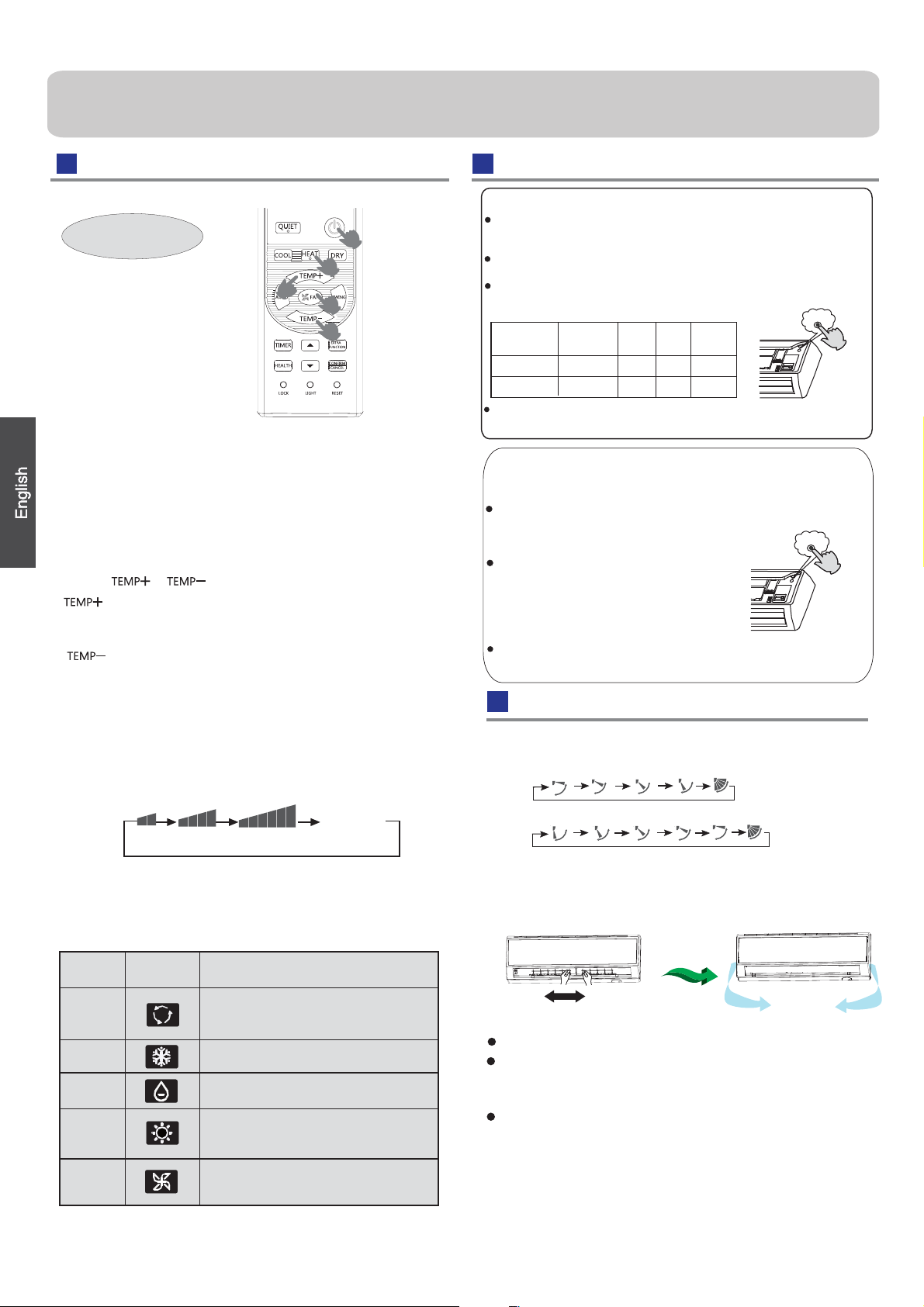
Air Flow Direction Adjustment
Press FAN button. For each press, fan speed
follows:
Remote controller:
Press
button
Every time the button is pressed, temp.setting
increase 1
o
C,if kept depressed, it will increase
rapidly
Every time the button is pressed, temp.setting
decrease 1
o
C,if kept depressed, it will
decrease rapidly
Select a desired temperature.
4.Fan speed selection
3.Select temp.setting
Air conditioner is running under displayed fan speed.
When FAN is set to AUTO, the air conditioner
automatically adjusts the fan speed according to room
temperature.
1. Unit start
Press ON/OFF on the remote controller, unit starts.
Base Operation
Remote controller
1.Status display of air flow
When restart after remote turning off, the remote
memorize the previous
Move the vertical blade by a knob on air
to adjust left and right direction referring to Fig.
2.Left and right air flow adjustment
(manual)
Cautions:
When adjusting the flap by hand,turn off the unit.
When humidity is high,condensate water might occur
adjusted to left or
It is advisable not to keep horizontal flap at downward
position for a long time in COOLor DRY
otherwise, condensate water might occur.
conditioner
Emergency operation and test operation
at air outlet if all vertical louvers are
right.
mode ,
controller will automatically
Note:
set swing position.
changes as
'
Operation
Mode
Remote
Controller
Note
In DRY mode , when room temperature becomes lower
than temp.setting+2
o
C, unit will run intermittently at LOW
speed regardless of FAN setting.
Under the mode of auto operation, air conditioner will
automatically select Cool or Heat operation according to
room temperature. When FAN is set to AUTO the air
conditioner automatically adjusts the fan speed according
to room temperature.
In FAN operation mode , the unit will not operate in COOL or
HEAT mode but only in
FAN mode, AUTO is not available in
FAN mode. And temp. setting is disabled. In FAN mode,
sleep operation is not available.
Emergency Operation:
Use this operation only when the remote controller is defective
or lost, and with function of emergency running, air conditoner
can run automatically for a while.
When the emergency operation switch is pressed, the " Pi "
sound is heard once, which means the start of this operation.
When power switch is turning on for the first time and
emergency operation starts, the unit will run automatically in
the following modes:
Room
temperature
Designated
temperature
Timer
mode
Fan
speed
Operation
mode
Above 23
o
C
Below 23
o
C 23
o
C
26
o
C
No
AUTO
AUTO
COOL
HEAT
No
It is impossible to change the settings of temp. and fan speed,It
is also not possible to operate in timer or dry mode.
temperature is below 16
o
C, do not use it in the
Test operation:
Use this switch in the test operation when the room
normal operation.
your finger from the switch: the cooling
Continue to press the test operation
switch for more than 5 seconds . After
you hear the "Pi" sound twice,
release
Test ope ration switch is the same as emergency switch.
operation starts with the air flow speed "Hi".
Under this operation mode,the fan motor of indoor
unit will run in high speed.
LOW
MED HI
COOL/DRY:
HEAT:
Initial state
AUTO
2. Select operation mode
COOL button:Cooling mode
HEAT button: Heating mode
DRY button: Dehumidify mode
Display
circulated
Pi
Pi Pi
DRY
COOL
AUTO
HEAT
FAN
In HEAT mode, warm air will blow out after a short
period of the time due to cold-draft prevention function.
When FAN is set to AUTO, the air conditioner automatically
adjusts the fan speed according to room temperature.
2

Operation
Sleep Operation
If the wind speed is high or middle before setting for the
sleep, set for lowing the wind speed after sleeping.
If it is low wind, no change.
5.Set the wind speed change when sleeping
Operation Mode
1. In COOL,DRY mode
SLEEP operation starts SLEEP operation stops
SLEEP
operation starts
SLEEP
operation stops
Approx.6hrs
1 hr
1 hr
1 hr
3 hrs
3 hrs
Rises 1
O
C
Rises 1
O
C
Rises 1
O
C
Temp.setting
Temp.setting
Unit stop
Unit stop
In COOL, DRY mode
In HEAT mode
Decreases 2
O
C
Decreases 2
O
C
1 hr
2.
3.
In HEAT mode
In AUTO mode
4. In FAN mode
It has no SLEEP function.
Note
When TIMER function is set, the sleeping function can’t be
set up .After the sleeping function is set u
p
,
TIMER function, the sleeping function will be cancelled; the
machine will be in the state of
timing-on.
POWER/QUIET Operation
1 hours after SLEEP mode starts,temp.will become
higher than temp.setting.After another 1 hours,temp.rises
by 1 futher.The unit will run for further
6 hours then stops
Temp. is higher than temp.setting so that room temperature
won’t be too low for your sleep.
1 hours after SLEEP mode starts,temp will become 2
lower than temp.setting.After another 1 hours,temp
decrease by 2
rises
by 1 futher.The unit will run for further 3 hours then
stops.Temp.is lower than temp. setting so that room
temperature won’t be
too high for your sleep.
The unit operaters in corresponding sleep mode
adapted to the automatically selected operation
mode.
O
C
O
C futher.After more another 3 hours,temp.
O
C
1
O
C
O
C
if user resets
Press button to enter additional options, when
cycle display to , will flash. And then press
enter to sleep function.
(1)
POWER Operation
(2)
QUIET Operation
Note ˖
When you need rapid heating or cooling, you can use this function.
You can use this function when silence is needed for rest or reading.
During POWER operation, in rapid HEAT or COOL mode ,
the room will show inhomogeneous temperature distribution.
Long period QUIET operation will cause effect of not too
cool or not too warm.
Press QUIET button, the remote controller will show ,
and then achieve to the quiet function. Press again this
QUIET button , the quiet function will be cancelled.
Press button to enter additional options, when cycle
display to , will flash,and then press ,enter to
power function. When cancel the function, please enter
additional options again and to cancel power function.
3

Operation
1.After unit starts, select your desired operation mode.
2.Press TIMER button to change TIMER mode. Every
time the button is pressed, display changes as follows:
Remote controller:
BLANK
TIMER ON TIMER OFF TIMER ON-OFF
Then select your desired TIMER mode (TIMER ON or
TIMER OFF or TIMER ON-OFF). " "or " "will flash.
3.Press / button to set time.
It can be adjusted within 24 hours.
Hints:
After replacing batteries or a power failure happens, time
setting should be reset.
According to the Time setting sequence of TIMER ON or
TIMER OFF, either Start-Stop or Stop-Start can be achieved.
Timer On/Off On-Off Operation
CE
All the products are in conformity with the following
European provision:
- Low Voltage Directive 73/23/EEC
- Low Voltage Directive 2006/95/EC
-Electomagnetic CompatibilitY 89/336/EEC
-Electomagnetic CompatibilitY 2004/108/EC
ROHS
The products are fulfilled with the requirements in the
directive 2002/95/EEC of the European parliament and of
council on the Restriction of the use of Certain Hazardous
Substances in Electrical and Electronic Equipment (EU
RoHS Directive)
WEEE
DISPOSAL REQUIREMENTS:
Your air conditioning product is marked with this
symbol.This means that electrical and electronic
products shall not be mixed with unsorted
household waste. Do not try to dismantle the
system yourself : the dismantling of the air
EUROPEAN REGULATIONS
CONFORMITY FOR THE MODELS
1
1+2=
kg
R410A
2
kg
2=
1=
B
C
D
FE
kg
A
This product contains fluorinated greenhouse gases covered by
the Kyoto Protocol. Do not vent into the atmosphere.
Refrigerant type:R410A
GWP* value:1975
GWP=global warming potential
Please fill in with indelible ink,
• 1 the factory refrigerant charge of the product
• 2 the additional refrigerant amount charged in the field and
• 1+2 the total refrigerant charge
on the refrigerant charge label supplied with the product.
The filled out label must be adhered in the proximity of the product
charging port (e.g. onto the inside of the stop value cover).
A contains fluorinated greenhouse gases covered by the Kyoto
Protocol
B factory refrigerant charge of the product: see unit name plate
C additional refrigerant amount charged in the field
D total refrigerant charge
E outdoor unit
F refrigerant cylinder and manifold for charging
IMPORTANT INFORMATION REGA-
RDING THE REFRIGERANT USED
In accordance with the directive 2002/96/CE of the European
parliament, herewith we inform the consumer about the dis-
posal requirements of the electrical and electronic products.
conditioning system,treatment of the refrigerant, of oil and of
other part must be done by a qualified installer in
accordance
with relevant local and national legislation. Air conditioners
must be treated at a specialized treatment facility for reuse,
recycling and recovery. By ensuring this product is disposed
of correctly, you will help to prevent potential negative cons-
equences for the environment and humen health. Please
contact the installer or local authority for more information.
Battery must be removed from the remote controller and dis-
posed of separately in accordance with relevant local and
nationl legislation.
Contains fluorinated greenhouse gases
covered by the Kyoto Protocol
Healthy airflow Operation
1.Press to starting
Setting the comfort work conditions.
2.The setting of healthy airflow function
Note:
1.After setting the healthy airflow function, the position
grill is fixed.
4.In cooling and dry, using the air conditioner for a long
time under the high air humidity, condensate water may
occur at the grille .
3.The cancel of the healthy airflow function
Notice: Do not direct the flap by hand. Otherwise, the
grille will run incorrectly. If the grille is not run correctly, stop
for a minute and then start, adjusting by remote
controller.
2.In heating, it is better to select the
3.In cooling, it is better to select the
mode.
mode.
TIMER OFF-ON
0.5h
0.5h 0.5h
0.5h
Press the button for each time, setting time in the first
12 hours increased by 0.5 hour every time, after 12
hours,increased by 1 hour every time.
Press the button for each time, settiing time in the first
12 hours decreased by 0.5 hour every time, after 12
hours,decreased by 1 hour every time.
After adjust the time,press button and confirm the
time ON or OFF button will not flash any more.
4.Confirm timer setting
5.Cancel timer setting
Press the timer button by times until the time display
eliminated.
Press button to enter additional options,Press this
button continuously, the louvers location will cycle between
in the following three locations, to choose the swing location
what you needed,and then press button to confirm.
Press button to enter additional options,Press this
button continuously, the louvers location will cycle between
in the following three locations again,and then press
button to cancel.
Healthy
airflow
upwarder
Healthy
airflow
downwarder
Present
position
4
Indoor Unit Installaion
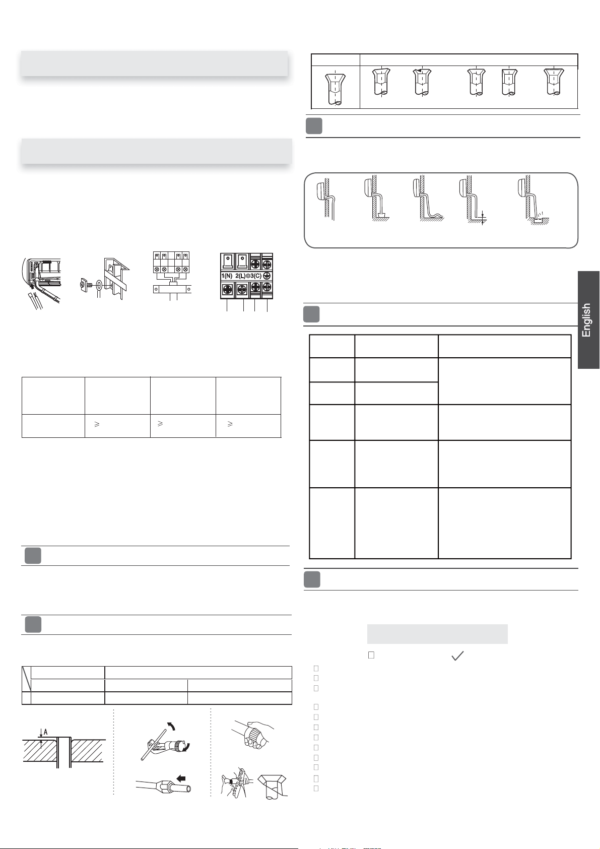
Driverƽ
Torque wrench
ƽ
(17mm,22mm,26mm)
Nipperƽ
Reamerƽ
Hacksawƽ
Pipe cutterƽ
Gas leakage detector orƽ
soap-and-water solution
Hole core drillƽ
Flaring toolƽ
Spanner(17,19 and 26mm)ƽ
Knifeƽ
Measuring tapeƽ
Necessary Tools for Installation
Power Source
Before inserting power
into receptacle, check the voltage without
fail.
The power
supply is the same as the
corresponding nameplate.
Install an exclusive branch circuit of the power.
Areceptacleshallbesetupin a distancewherethepowercable
can
be
reached.
Donotextendthecablebycuttingit.
Selection of Installation Place
Place, robust not causing vibration, where the body can be
supported suf ficiently.
ƽ
Place, not affected by heat or steam generated in the vicinity,
where inlet and outlet of the
unit are not disturbed.
ƽ
Place, possible to drain easily, where piping can be conne-
cted with the outdoor unit.
ƽ
Place,wherecoldaircanbespreadin a roomentirely.
ƽ
Place, nearby a power receptacle, with enough space around.
ƽ
Place where the distance of more than lm from televisions,
radios, wireless apparatuses
a
nd fluorescent lamps can be
left.
ƽ
In the case of fixing the remote controller on a wall, place
where the indoor unit can
receive signals when the fluore-
scent
ƽ
lamps
in the room are lightened.
ƽ
ƽ
ƽ
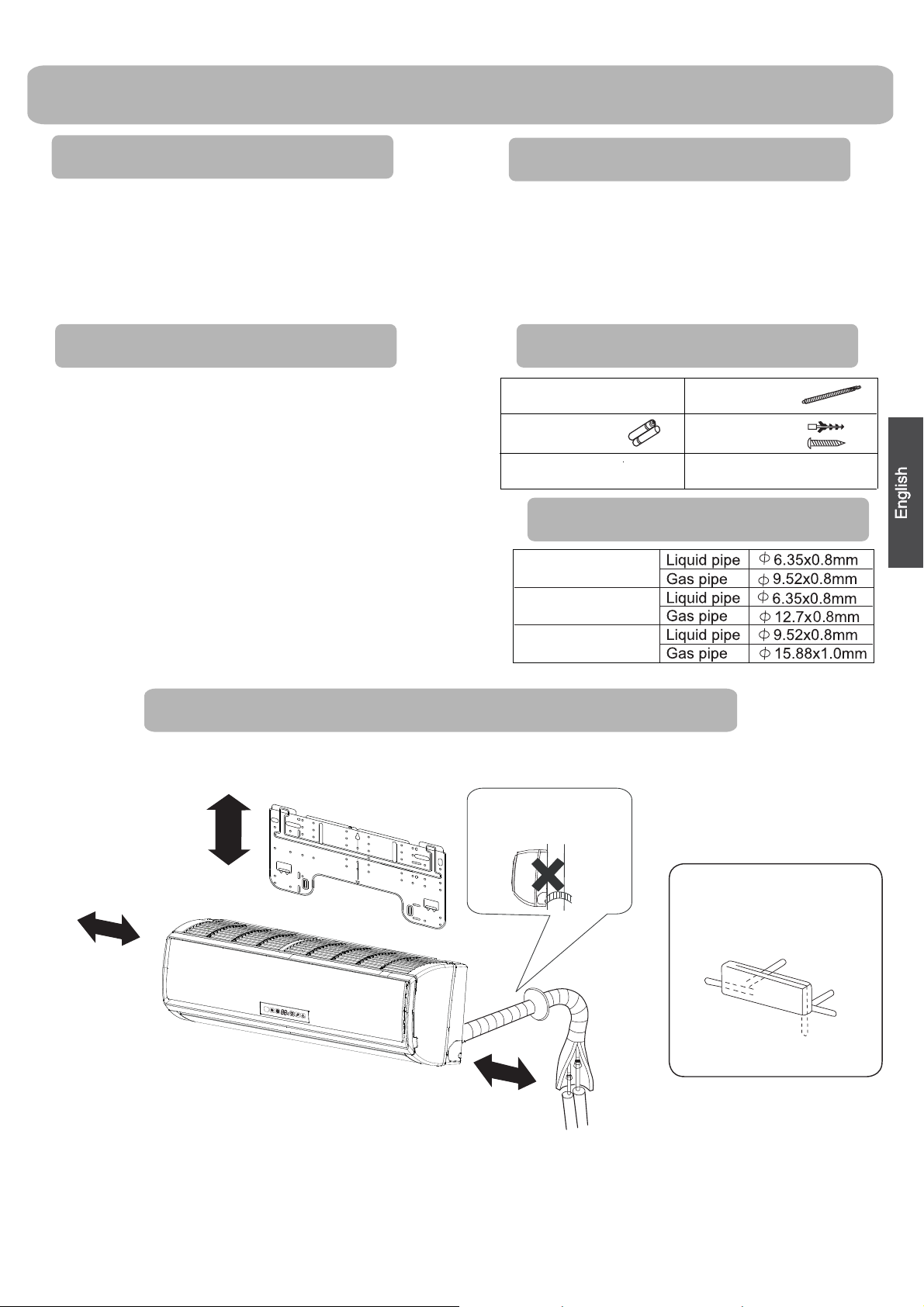
The distance between
theindoorunitandthe
floor should be more
than 2m.
ThemodelsadoptHFCfreerefrigerantR410A
more than
10cm
more than 15cm
more than 10cm
Arrangement of piping
directions
Rear left
Left
Rear
right
Right
Below
Attention must be paid to
the rising up of drain hose
Remote controller (1)
R-03 dry battery (2)
Mounting plate (1)
Drain hose (1)
Ø4X25 Screw
(4)
Plastic cap (4)
Accessory Parts
FOR 07K 09K 12K
FOR 18K
FOR 24K
Selection of Pipe
Drawing for the installation of indoor units
ƽ
Air purifying filter(Optional) (1)
Please be subject to the actual product purchased,the above picture is just for your reference.
5
Indoor Unit Installation
Fix to side bar and lintel a mounting bar, Which is separately sold, and
then
ƽ
fasten the plate to the fixed mounting bar.
Refer to the previous article, “ When the mounting plate is
ƽ
position of wall hole.
Make a hole of 70 mm in diameter, slightly descending to outside the wall
ƽ
Install piping hole cover and seal it off with putty after installation
ƽ
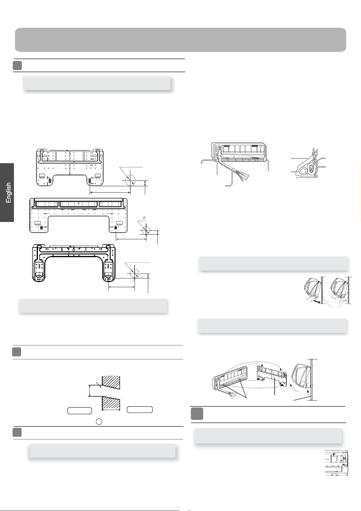
1.Carryout,basedontheneighboringpillarsorlintels, a
tobefixedagainstthewall,thentemporarilyfastentheplate
with
one steel nail.
2. Make sure once more the proper level of the p
late, by
hanging a thread
with a
weight from the central top of the plate, then fasten securely the
plate with
the
attachment steel nail.
3. Find the wall hole location A using a measuring tape
When the mounting plate is fixed side bar and lintel
FittingoftheMountingPlateand
Positioning of the wall Hole
Lid for right
piping
Lid for under piping pipe
Fix with adhesive tape
Lid for left piping
Indoor/outdoorelectriccableanddrainhosemustbeboundwith
efrigerant
ƽ
piping by protecting tape.
[Otherdirectionpiping ]
Cut away, with a nipper, the lid for piping according to the piping
direction
and
ƽ
then bend the pipe according to theposition of wall
hole. When bending, be
careful not to crash
pipes.
Connectbeforehandtheindoor/outdoorelectriccable,
ƽ
and then
pull out the
connected to the heat insulation of connecting part
specially.
proper leveling
for
the plate
first fixed “,
for the
Making a Hole on the Wall and Fitting the Piping Hole Cover
Drawingofpipe
Installation of the Indoor Unit
[Rearpiping ]
Drawpipesandthedrainhose,thenfastenthemwiththeadhesivetape
ƽ
[Left
·
Left-rear piping ]
In case of left side piping, cut away, with a nipper, the lid for left
piping.
ƽ
In case of left-rear piping, bend the pipes according to the piping
direction to
ƽ
the mark of hole for left-rear piping which is marked on
heat
insulation materials.
1. Insert the drain hose into the dent of heat insulation materials of
indoor
unit.
2. Insert the indoor/outdoor electric cable from backside of indoor
unit,
and pul
lit
outonthefrontside,thenconnect them.
3.Coattheflaringsealfacewithrefrigerantoilandconnect pipes.
Cover the connection part with heat insulation materials closely,
and
make sure
fixingwithadhesivetape
Hangsurelytheunitbodyontotheupper
notches of the
ƽ
mounting plate. Move the body
from
side to side to verify its
secure fixing.
Inordertofixthebodyontothemounting
plate,hold up
ƽ
thebodyaslantfromthe
underside and
then put it down
perpendicularly.
R
emove terminal cover at rig
ht bottom corner of
indoor unit, then take
ƽ
offwiringcoverby removing
its screws.
mounting plate
When you unload the indoor unit,please use your hand to arise
slightly and lift the unit aslant until it leaves the mounting plate.
agraffe
mounting plate
ƽ
the body to leave agraffe,then lift the bottom of the body outward
Heat insulation
material
Drain hose
Piping
Pipe supporting
plate
Indoor/outdoor electric cable
Indoor side
Outdoor side
Ø70mm
Wall hole
Thickness of wall
(Section of wall hole)
Piping hole pipe
G
When the mounting plate is first fixed
Fixing the indoor unit body
Unloading of indoor unit body
Connecting the indoor/outdoor Electric Cable
Removing the wiring cover
A=145mm
30mm
B=
70mm
Ø
A=150mm
B= 70mm
35mm
A=145mm
B=
70mm
Ø
30mm
6
1. Insert from outside the room cable into left side of the wall
hole,inwhichthepipehasalreadyexisted.
2.Pulloutthecableonthefrontside,andconnectthecable
making a loop.
When connecting the cable, confirm the terminal number of indoor and
outdoor units carefully. If wiring is not correct, proper operation can not
becarriedoutandwillcausedefect.
Insertthecablefromtheback
ƽ
side of the u nit, then pull it out
on the front side.
Loosen the screws and insert
ƽ
the cable ends fully into
terminal block, then
tighten the screws.
Pull the cable slightly to
ƽ
make sure the cables have
been properly inserted and
tightened.
After the cable connection,
ƽ
never fail to fasten the connected cable with the
wiring cover.
When connecting the cable after installing the indoor unit
When connecting the cable before installing the indoor unit
Note:
1.Ifthesupplycordisdamaged,itmustbereplacedbythemanufacturerorits
service agent or a similar qualified person. The type of connecting wire is
H05RN-F
or H07RN-F.
2.IfthefuseonPCboardisbrokenpleasechangeitwiththe
type of
3.Thewiringmethodshouldbeinlinewiththelocalwiringstandard.
4. After installation, the power plug should be easily reached.
5. A breakershouldbeincorporatedintofixedwiring.Thebreakershouldbe
all-pole
switchandthedistancebetweenitstwoc
ontactsshouldbenotless
than 3mm.
T.3.15A/250VAC (Indoor).
To Outdoor unit
Model
Connecting wiring
4G0.75mm
2
4G0.75mm
2
4G0.75mm
2
AS07GS2ERA
AS09GS2ERA
AS12GS2ERA
AS18GS2ERA
AS24GS2ERA
Thepowersourcemustbeexclusivelyusedforair
ƽ
conditioner.
In the case of installing an air conditioner in a moist place,
ƽ
please install
an ea
For installation in other places, use a circuit breaker as far
ƽ
as possible.
Pipecuttingiscarriedoutwith a pipecutterandbursmust beremoved.
Afterinsertingtheflarenut,flaring workiscarriedout.
Power Source Installation
Cutting and Flaring Work of Piping
FlaretoolforR410A Conventionalflaretool
Clutch-type clutch-type(Rigid-type) Wing-nut type (Imperial-type)
A 0~0.5mm 1.0~1.5mm 1.5~2.0mm
rth leakage breaker.
Lean
Damage of flare Partial Too outside
Correct Incorrect
On Drainage
It becomes
high midway.
The gap with the
ground is too small.
Thereisthebad
smell from a ditch
It waves.
The end is imm-
ersedinwater.
Pleaseinstallthedrainhosesoastobedownwardslopewithoutfail.
Pleasedon’tdothedrainageasshownbelow.
ƽ
ƽ
Pleasepourwaterinthedrainpan of theindoorunit,and
ƽ
is carried out surely to outdoor.
In case that the attached drain hose is in a room, please
ƽ
apply heat
insulation
to
Less than
5cm
confirm that
drainage
it without fail.
Crack
Indoor unit
Check Items for Test Run
Gasleakfrompipeconnecting?
Heat insulation of pipe connecting?
Are the connecting wirings of indoor and outdoor firmly
Is the connecting wiring of indoor and outdoor firmly fixed?
Is drainage securely carried out?
Is the earth line securely connected?
Istheindoorunitsecurelyfixed?
Is power source voltage abided by the code?
Is there any noise?
Isthelampnormallylighting?
Arecoolingandheating(wheninheatpump)performednormally?
Is the operation of room temperature regulator normal?
Pleasekindlyexplaintoourcustomershowto
operate
through the instruction manual.
inserted to the terminal block?
Ƶ
Put check mark
in boxes
Flare tooling die
1.Cut pipe
2.Remove burs
3.Inserttheflarenut
4.Flare pipe
ƽ
ƽ
On Drainage
Check for Installation and Test Run
Code
indication
Trouble description
Analyze and diagnose
E1
E2
E4
E7
E14
Indoor fan motor
malfunction
Heat-exchange
sensor failure
Indoor EEPROM
error
Communication
fault between
indoor and outdoor
units
Indoor fan motor
malfunction
Operation halt due to breaking
of wire inside the fan motor;
Operation halt due to breaking
of the fan motor lead wires;
Detection error due to faulty
indoor unit PCB;
Indoor unit- outdoor unit
signal
transmission error due to wiring
error;
Faulty PCB;
Faulty EEPROM data;
Faulty EEPROM ;
Faulty P CB;
Faulty connector connection;
Faulty thermistor;
Faulty PCB;
7

Maintenance
Setting of proper room
temperature
Close doors and windows
during operation
If the unit is not to be used
for a long time, turn off the
power supply main switch.
Use the timer effectively
Use the louvers effectively
Do not block the air inlet
or outlet
Proper
temperature
During cooling operation
prevent the penetration
of
direct sunlight with
curtain or blind
OFF
Remote Controller Indoor Body
1.Open the lnlet Grille
2.Detach the standard air filter
3.Attach Air Purifying Filter
4.Attach the standard air filter
(Necessar
y installation)
5.Close the Inlet Grille
Close the Grille surely
Slide the knob slightly up
ward to
release the filter, then withdraw it.
Put air purifying filter appliances into the
right and left filter frames.
NOTE:
The photocatalyst air purifying filter will be solarized in fixed
time. In normal family,
it will be solarized every 6 months.
Prop up the inlet grille by using a
small device named grille-support
ATTENTION:
Please keep the bacteria-killing medium air purifying filter in
avoid long time directly sunshine
when you stop using it,or its ability of sterilization will
be
reduced.
The bacteria-killing medium air purifying filter will be used
for a long time,no need for replacement. But in the period
of using them ,you should remove the dust frequently by
which located in the right side of
the indoor unit.
using vacuum cleaner or flaping them lightly,otherwise ,
its performance will be affected.
the cool and dry conditions
For Smart Use of The Air Conditioner
Replacement of Air Purifying Filter
The white side of the photocatalyst air purifying filter
face outside,and the black side face the unit The green
side of the bacteria-killing medium air purifying filter face
outside,and the white side face the unit.
Do not usewater,wipe the controller
with a dry cloth.Do not use glass
cleaner or chemical cloth.
wipe the air conditioner by using a
soft and dry cloth.For serious stains,
use a neutral detergent diluted with
water.Wring the water out of the
cloth before wiping,then wipe off the
detergent completely.
Air Filter cleaning
Open the inlet grille by pulling it upward.
Remove the filter.
Clean the filter.
Attach the filter.
Close the inlet grille.
Push up the filter's center tab slightly until it is
from the stopper, and remove the filter do
wnw
ard.
Use a vacuum cleaner to remove dust, or wash the filter with
water.After washing, dry the filter completely in the shade.
Attach the filter correctly so that the "FRONT" indication
facing to the front.Make sure that the filter is
fixed behind the stopper.If the right
attached correctly, that
Do not use the following for cleaning
Gasoline,benzine, thinner or cleanser
ay
damage the coating of the unit.
Hot water over 40
O
C(104
O
F) may
discoloring or deformation.
Once every
two weeks
m
cause
released
is
completely
and left filters are not
may cause defects.
Detach old Air Purifying Filter
8
the power supply cord
and so on.
2.
Do not install in the place where there is any
possibility of inflammable gas leakage around the unit.
3.Do not get the unit exposed
to vapor or oil steam.
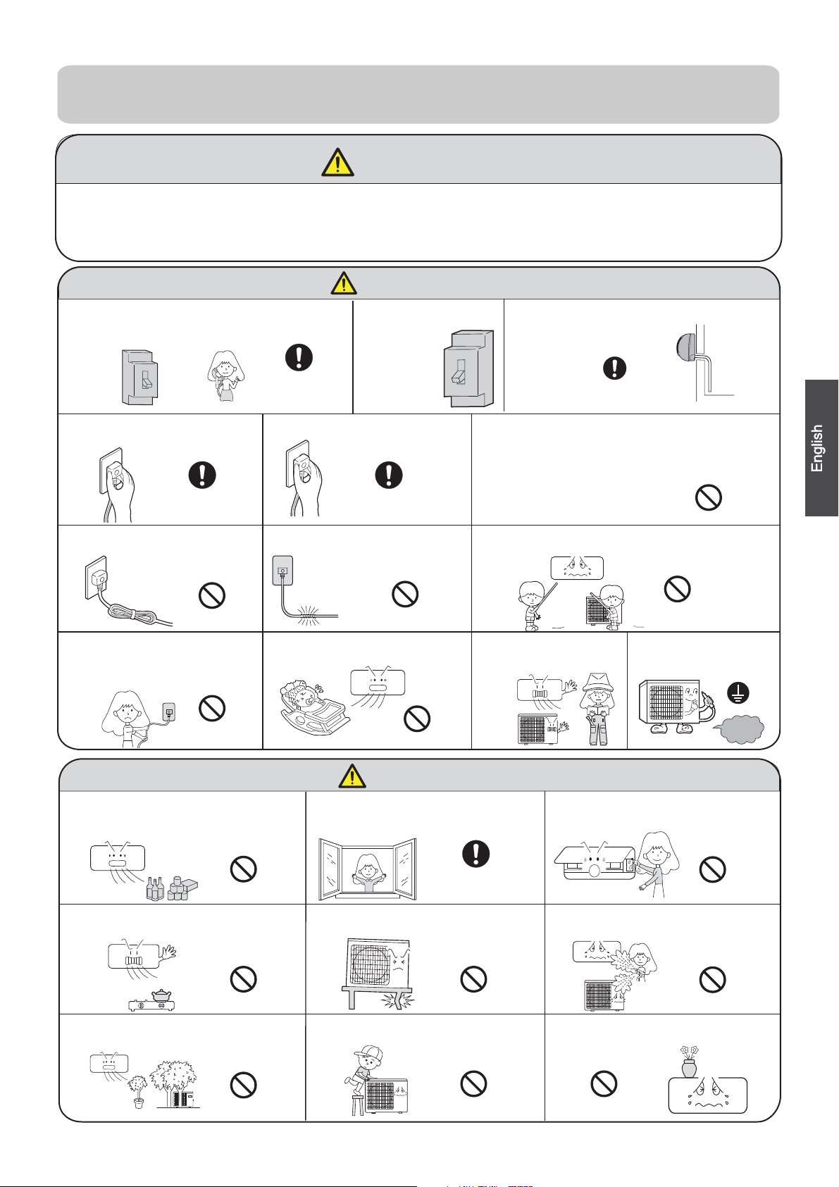
Cautions
Please call Sales/Service Shop for the Installation.
Do not attempt to install the air conditioner by yourself because improper works
may cause electric shock, fire, water leakage.
Connect the earth
cable.
earthing
WARNING
When abnormality such as burnt-small found,
immediately stop the operation button and
contact sales shop.
OFF
Use an exclusive
power source
with a circuit
breaker
ENFORCEMENT
Connect power supply cord
to the outlet completely
Use the proper voltage
Do not use power supply
cord in a bundle.
Take care not to damage
the power supply cord.
1.Do not use power supply cord extended
or connected in halfway
STRICT
ENFORCEMENT
STRICT
STRICT
ENFORCEMENT
PROHIBITION
PROHIBITION
PROHIBITION
PROHIBITION
Do not start or stop the
operation by disconnecting
Do not channel the air flow directly
at people, especially at infants or
the aged.
Do not try to repair or
reconstruct by yourself.
Do not use for the purpose of storage of
food, art work, precise equipment,
breeding, or cultivation.
CAUTION
Take fresh air occasionally especially
when gas appliance is running at the
same time.
PROHIBITION
STRICT
ENFORCEMENT
Do not operate the switch with
wet hand.
PROHIBITION
PROHIBITION
PROHIBITION
PROHIBITION
PROHIBITION
Do not install the unit near a fireplace
or other heating apparatus.
Check good condition of the
installation stand
Do not pour water onto the unit
for cleaning
PROHIBITION
Do not place animals or plants in
the direct path of the air flow
Do not place any objects on or
climb on the unit.
Do not place flower vase or water
containers on the top of the unit.
Do not insert objects into the air
inlet or outlet.
PROHIBITION
PROHIBITION
PROHIBITION
STRICT
ENFORCEMENT
Check proper
installation of the
drainage securely
WARNING
9

Trouble shooting
Normal
Performance
inspection
Noise is heard
Phenomenon
Cause or check points
The system
immediately.
Smells are
generated.
Mist or steam are
Multiple
check
Poor cooling
When unit is stopped, it won't restart
elapsed to protect the system.
When the electric plug is pulled out
and reinserted, the protection circuit
During unit operation or at stop,
a swishing or gurgling noise may
(This noise is generated by
refrigerant flowing in the system.)
During unit operation, a cracking
noise may be heard.This noise is
temperature changes.
Should there be a big noise from
filter may be too dirty.
This is because the system
circulates smells from the interior
During COOL or DRY operation,
This is due to the sudden cooling
Is power plug inserted?
Is there a power failure?
Is fuse blownout?
Is the air filter dirty?
Are there any obstacles before
Is temperature set correctly?
Are there some doors or
Is there any direct sunlight
through the window during the
Are there too much heat sources
or too many people in the room
In dry mode,
fan
speed can’t be
changed.
In DRY mode, when room temperature
setting+2
o
C,unit will run
regardless of FAN setting.
during cooling operation?
cooling operation?(Use curtain)
windows left open?
inlet and outlet?
Normally it should be cleaned
every 15 days.
intermittently at LOW speed
becomes lower than temp.
indoor unit may blow out mist.
of indoor air.
air such as the smell of furniture,
paint, cigarettes.
air flow in unit operation, air
generated by the casing expanding
or shrinking because of
be heard.At first 2-3 minutes after
unit start, this noise is more noticeable.
will work for 3 minutes to protect the
air conditioner.
immediately until 3 minutes have
Cautions
3. If the fuse of indoor unit on PC board is
it with the type of
T. 3.15A/ 250V
outdoor
broken,change it with the type of
T.25A/250V
Do not obstruct or cover the ventilation
conditoner.Do not put fingers
inlet/outlet and
swing louver.
Do not allow children to play with the air
conditioner
case should children be
allowed to sit on the outdoor unit.
The refrigerating circuit is leak-proo f.
1.Applicable ambient temperature range:
Specifications
The machine is adaptive in following
situation
The power plug and connecting cable
acquired the local
2. If the power supply cord is damaged, it
must be replaced
manufacturer
qualified
person.
4. The wiring method should be in line with
the local wiring
5. After installation, the power plug should
be easily reached.
6. The waste battery should be disposed
properly.
7. The appliance is not intended for use
persons
without supervision.
8.Young children should be supervised
with
the appliance.
9. Please employ the proper power plug,
cord.
11.In order to protect the units,please turn
30 seconds
later, cutting off the power.
10.
Cooling
Indoor
Maximum:D.B/W.B
Maximum:D.B/W.B
D.B
Maximum:D.B
D.B
Minimum:D.B/W.B
Maximum:D.B/W.B
Minimum:D.B/W.B
Outdoor
Indoor
Outdoor
Heating
32
o
C/23
o
C
24
o
C/18
o
C
o
C/-8
o
C
46
o
C/26
o
C
18
o
C
27
o
C
21
o
C/15
o
C
Outdoor
Maximum:D.B/W.B
Minimum:D.B
24
o
C/18
o
C
-15
o
C
(INVERTER)
o
C
7
-
Minimum:
Minimum:
grille of the air
or any other things into the
.In no
or its service agent or a similar
broken,please
. If the fuse of
standard.
by young children or
to ensure that th
ey
which fit into the
must have
off the A/C first,
Before asking for service, check the following
first.
blown out.
does not restart
by the
change
unit is
infirm
do not play
p
ower supply
attestation.
and at least
Haier Group
Address:No.1 Haier Road,Hi-tech Zone,Qingdao 266101 P.R.China
Contacts: TEL +86-532-8893-6943;FAX +86-532-8893-1010
Website: www.haier.com
15
10
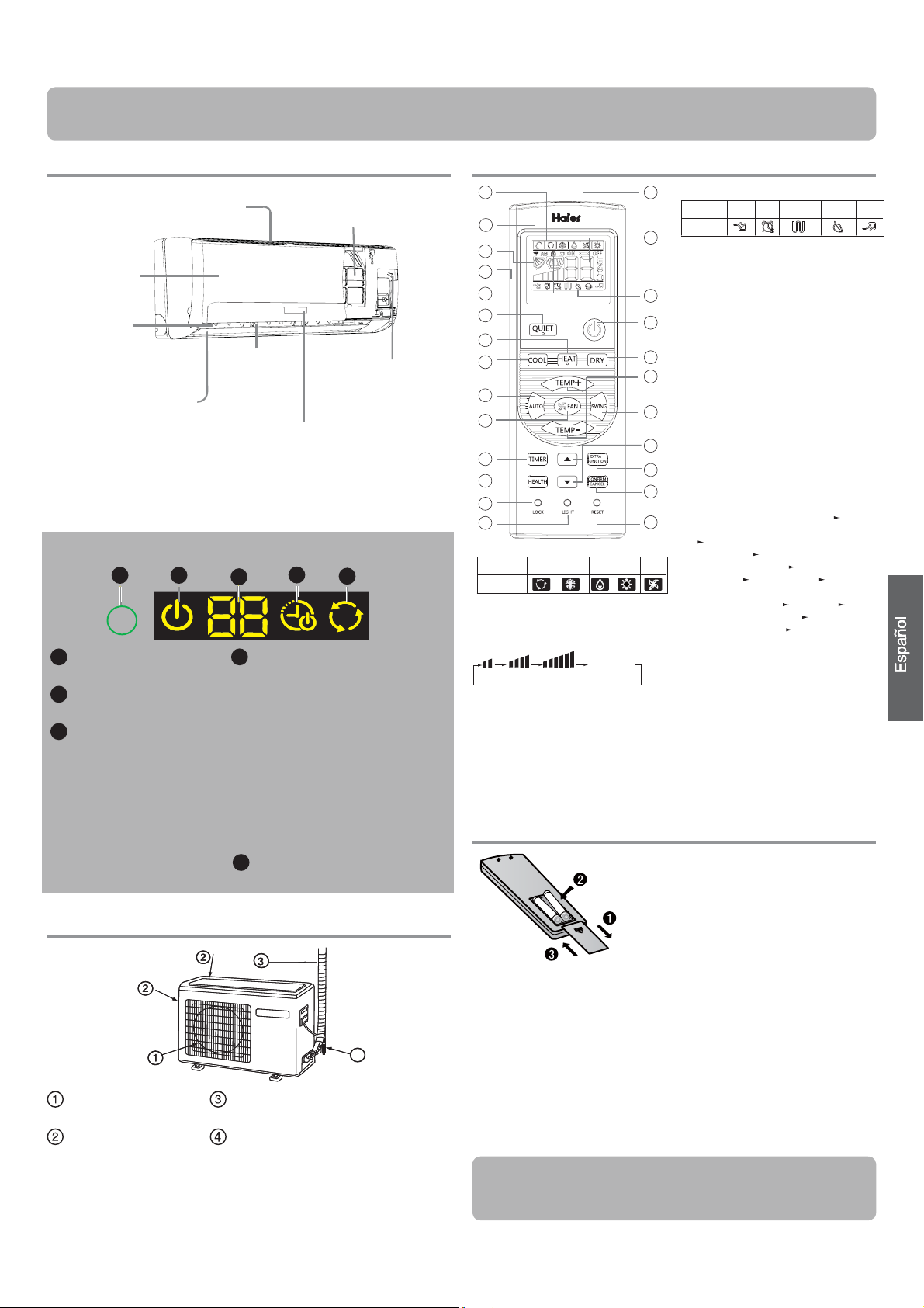
Componentes y funciones
Unidad interior
Recuerde que la ilustración anterior podría no reflejar fielmente el
producto adquirido y debe utilizarse únicamente como referencia.
Unidad exterior
SALIDA DE AIRE
TUBOS DE CONEXIÓN Y CABLEADO
ELÉCTRICO
ENTRADA DE AIRE
MANGUITO DE DRENAJE
Recuerde que la ilustración anterior podría no reflejar
fielmente el producto adquirido y debe utilizarse únicamente
como referencia.
Mando a distancia
Instalación de las pilas
Extraiga la tapa de las pilas;
En la figura se muestra el modo
de carga de las pilas. 2 pilas
R-03, botón reinicio (botella);
Asegúrese de respetar los signos
"+" y "-";
Instale las pilas y vuelva a colocar de nuevo la tapa.
Nota:
La distancia entre el cabezal de transmisión de la señal y el orificio del
receptor debe ser de unos 7 m sin obstáculos.
Si se instalan lámparas fluorescentes o se utilizan teléfonos inalámbricos
en la sala, el receptor podría resultar perturbado al recibir las señales, por
lo que la distancia hasta la unidad interior deberá ser menor.
Si se activan todos los indicadores de la pantalla o no es posible
visualizarlos correctamente durante el uso, es señal de que las pilas se han
agotado. Por favor, cambie las pilas.
Si el mando a distancia no funciona normalmente durante su uso,
extraiga las pilas y vuelva a instalarlas pasados unos minutos.
1
2
3
4
Toma de entrada
Rejilla de
entrada de aire
Filtro purificador de aire
(interior)
Interruptor de
emergencia
Paleta vertical
(permite ajustar la
dirección
del
flujo
de
aire hacia la izquierda
y hacia la derecha)
Panel de indicadores
Alerón horizontal
(permite ajustar la dirección del
flujo de aire hacia arriba y hacia
abajo; no lo ajuste manualmente)
Salida de aire
1
4
2
3
5
1
Orificio del receptor de
señal
2
Indicador ENCENDIDO/
APAGADO
3
Pantalla de temperatura
ambiente
Al recibir una señal de mando a
distancia, muestra la temperatura
definida. El resto del tiempo se
muestra la temperatura de la sala.
Esta temperatura es sólo una
referencia.
4
Indicador TEMPORIZADOR DE
ENCENDIDO/APAGADO
INDICADOR TEMPORIZADOR
DE ENCENDIDO-APAGADO
Indicador de la función SUEÑO
Nota para reanudar después de errores
de alimentación:
pulse el botón de sueño diez veces en
menos de cinco segundos y acceda a
esta función después de escuchar cuatro
sonidos. Pulse el botón de sueño diez
veces en menos de cinco segundos y
acceda a esta función después de escuchar
dos sonidos.
5
Indicador FRÍO\CALOR\SECO\
AUTOMÁTICO
Panel de indicadores
4
1
2
3
4
5
9
10
11
12
13
14
15
16
17
22
23
24
25
19
20
21
8
18
7
6
8. Indicador de funciones adicionales
Modo de
funcionamiento
SILENCIO SUELO
Ayuda con calor
eléctrico
SALUDABLE INTENSO
Mando a
distancia
9. Botón SILENCIO
10. Botón CALOR
11. Botón FRÍO
12. Botón AUTOMÁTICO
13. Botón VENTILADOR
14. Botón TEMPORIZADOR
15. Botón SALUDABLE
16. Botón BLOQUEAR
Se utiliza para bloquear los botones y
la pantalla LCD.
17. Botón LUZ
Controla la activación y desactivación
de la iluminación del panel de
indicadores LED de la unidad interior.
18. Botón ENCENDIDO / APAGADO
19. Botón SECO
20. Botón TEMPERATURA
21. Botón OSCILACIÓN
22. Botón HORA
23. Botón FUNCIÓN ADICIONAL
Función: Dirección del aire
---
Posición de flujo de aire saludable
1
---
Posición de flujo de aire
saludable 2
---
Restablecer la posición
original de la aleta
---
Flujo de aire
horizontal
---
Jardín A-B
---
10 y
símbolo de calefacción mostrado
simultáneamente
---
Dormir
---
Calefacción eléctrica
---
Calefacción
eléctrica Potencia
---
Modo de
conversión Fahrenheit/Celsius
24. Botón CANCELAR/CONFIRMAR
Función: establecer y cancelar el
temporizador y otras funciones
adicionales.
25. Botón RESTABLECER
Si el mando a distancia presenta
alguna anomalía, introduzca un objeto
puntiagudo a través del orificio para
pulsar este botón y restablecer el
mando a distancia.
1. Indicador de modo
Modo de
funcionamiento
AUTOMÁTICO
REFRIGERACIÓN SECO CALEFACCIÓN VENTILADOR
Mando a
distancia
2. Indicador de envío de señal
3. Indicador de OSCILACIÓN
4. Indicador de VELOCIDAD DE
VENTILADOR
5. Indicador de BLOQUEO
6. Indicador
TEMPORIZADOR DE
APAGADO
TEMPORIZADOR DE
ENCENDIDO
7. Indicador de TEMPERATURA
La función Saludable no está disponible para algunas unidades.
BAJA MEDIA ALTA AUTOMÁTICO
Visualización
circular
Sugerencia:
Extraiga las pilas si no tiene intención de utilizar la unidad durante un
periodo largo de tiempo. Si observa alguna pantalla extraña después de
extraer las pilas deberá pulsar el botón Restablecer.
11
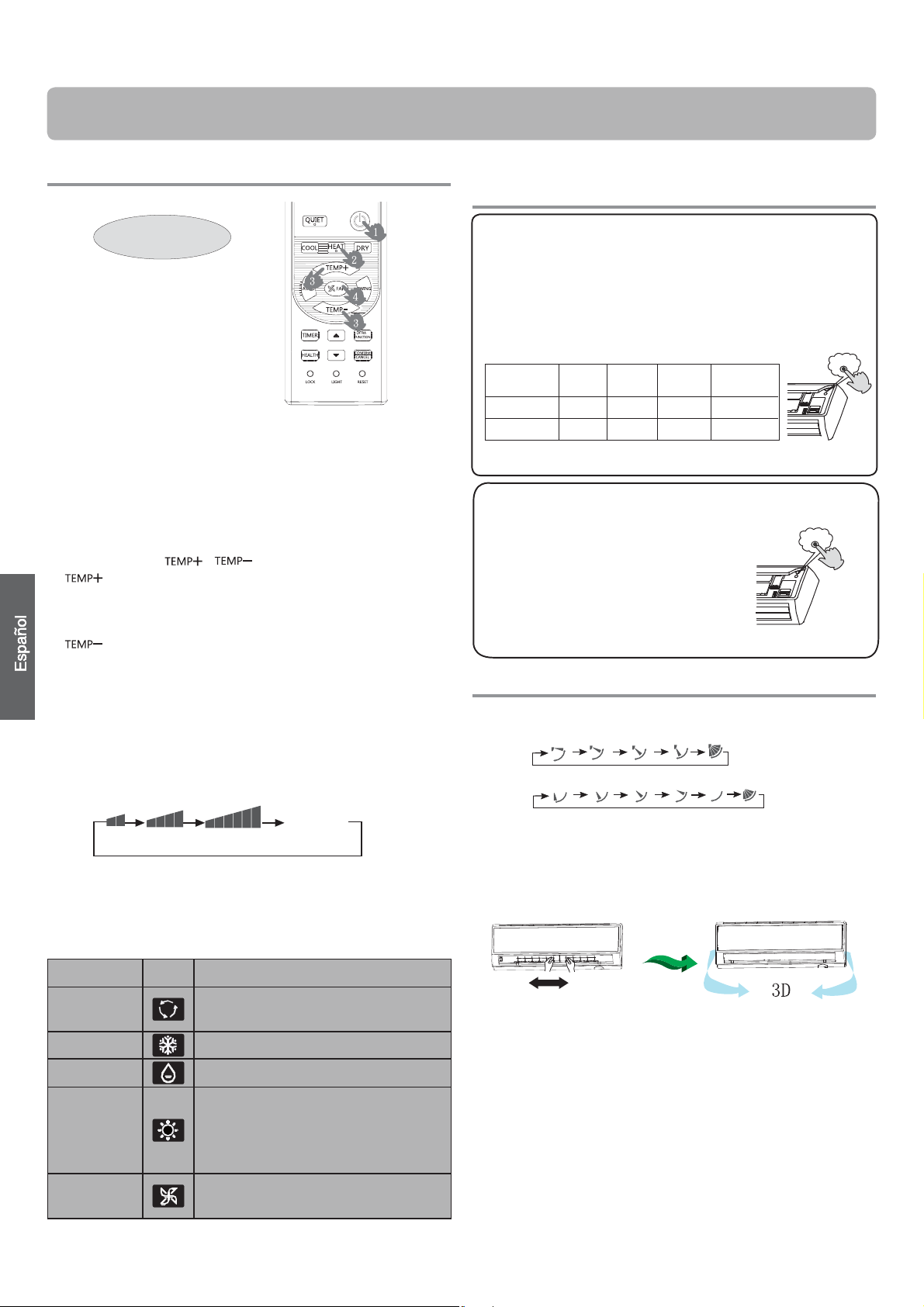
Funcionamiento
Funcionamiento básico
1. Arranque de la unidad
Pulse el botón de ENCENDIDO / APAGADO en el mando
a distancia para arrancar la unidad.
2. Selección del modo de funcionamiento
Botón FRÍO: modo de refrigeración
Botón CALOR: modo de calefacción
Botón SECO: modo de deshumidificación
3. Selección de la configuración de temperatura
Pulse el botón / .
Cada vez que pulse este botón, la configuración
de temperatura aumentará en 1 ºC. Si mantiene el
botón pulsado, la temperatura aumentará rápida-
mente.
Cada vez que pulse este botón, la configuración
de temperatura bajará 1 ºC. Si mantiene el botón
pulsado, la temperatura bajará rápidamente.
Seleccione la temperatura que desee.
4. Selección de la velocidad del ventilador
Pulse el botón VENTILADOR. Cada vez que pulse el
botón, la velocidad del ventilador
cambiará de acuerdo con el ciclo ilustrado a continuación:
Mando a distancia:
El aparato de aire acondicionado funciona según la veloci-
dad de ventilador indicada.
Si el VENTILADOR se configura en el modo AUTOMÁTICO,
el aparato de aire acondicionado ajustará automáticamente la
velocidad del mismo según la temperatura de la habitación.
Funcionamiento en modo de
emergencia en modo de prueba
Ajuste de dirección del flujo de aire
1. Indicador de estado flujo de aire
FRÍO/SECO:
CALOR:
2. Ajuste del flujo de aire hacia la izquierda y
hacia la derecha (manual)
Mueva la pala vertical por medio del mando del aparato de
aire acondicionado para ajustar la dirección del flujo de aire
hacia la izquierda o hacia la derecha, según lo indicado en
la ilustración.
Precauciones:
Apague la unidad antes de ajustar la posición del alerón
con la mano.
Si el nivel de humedad es alto podría condensarse
humedad en la salida de aire si se ajustan todas las lamas
verticales a la izquierda o la derecha.
Es aconsejable no mantener la aleta horizontal en
posición descendida durante mucho tiempo en el
modo FRÍO o SECO. De lo contrario podría producirse
condensación de agua.
Nota:
El mando a distancia carga automáticamente la última
posición de oscilación establecida al volver a poner en
marcha la unidad después de haberla detenido.
Mando a distancia
BAJA MEDIA ALTA AUTOMÁTICO
Visualización
circular
Modo de
funcionamiento
mando a
distancia
Nota
AUTOMÁTICO
En el modo de funcionamiento automático, el acondicionador de aire
seleccionará de forma automática la operación Frío o Calor en función de la
temperatura de la habitación. Si el VENTILADOR se configura en el modo
AUTOMÁTICO, el aparato de aire acondicionado ajustará automáticamente
la velocidad del mismo según la temperatura de la habitación.
REFRIGERACIÓN
SECO
En el modo SECO, cuando la temperatura de la sala es inferior a la
temperatura configurada +2ºC, el equipo funcionará de forma intermitente a
BAJA velocidad, independientemente de la configuración del ventilador.
CALEFACCIÓN
En el modo CALOR, el equipo distribuirá aire caliente después de un corto
periodo de tiempo durante el que se activará la función de prevención de
distribución de aire frío.
Si el VENTILADOR se configura en el modo AUTOMÁTICO, el aparato de
aire acondicionado ajustará automáticamente la velocidad del mismo según
la temperatura de la habitación.
Cuando se pase de una sola unidad en funcionamiento a dos o más
unidades, la unidad que se encuentre APAGADA no expulsará aire durante
los primeros 7 minutos y la temperatura mostrada podría ser diferente a la
temperatura real.
VENTILADOR
En el modo VENTILADOR, la unidad no funcionará en los modos de
REFRIGERACIÓN o CALEFACCIÓN, sino únicamente en el modo
VENTILADOR. El modo AUTOMÁTICO no está disponible en el modo
VENTILADOR. El ajuste de temperatura quedará deshabilitado. En el modo
VENTILADOR, la función Sueño no estará disponible.
Funcionamiento de emergencia:
Utilice esta operación únicamente cuando el mando a distancia
esté defectuoso o se haya perdido. Si la función de emergencia
está en funcionamiento, el acondicionador de aire podrá funcionar
automáticamente durante un tiempo.
Si presiona el botón de uso de emergencia escuchará el sonido "Pi" una
vez, lo cual indica que el modo de uso se ha activado.
Cuando se enciende el interruptor de alimentación por primera vez
y comienza el funcionamiento de emergencia, la unidad funcionará
automáticamente en los siguientes modos:
Temperatura de la
habitación
Temperatura
seleccionada
Modo de
temporizador
Velocidad del
ventilador
Modo de
funcionamiento
Por encima de 23
O
C26
O
C No AUTOMÁTICO REFRIGERACIÓN
Por debajo de 23
O
C23
O
C No AUTOMÁTICO CALEFACCIÓN
Es imposible cambiar la configuración de temperatura y velocidad del
ventilador, como tampoco es posible utilizar el modo de temporizador o seco.
Pi
Funcionamiento de prueba:
El interruptor de funcionamiento de prueba es similar al interruptor de emergencia.
Utilice este interruptor en el uso de prueba si la
temperatura de la sala es inferior a 16 ºC. No lo
utilice durante el uso normal.
Continúe pulsando el interruptor del uso de prueba
durante más de 5 segundos. Separe el dedo del
interruptor cuando el equipo emita dos veces el
sonido "Pi": el modo de refrigeración se iniciará con
el flujo de aire a velocidad "Alta".
Bajo este modo de funcionamiento el motor del ventilador de la unidad interior
funcionará a alta velocidad.
Pi Pi
Estado inicial
12
 Loading...