


MULTI-SPLIT AIR CONDITIONER
INSTALLATION MANUAL
Please read this manual carefully before installation.
Keep this operation manual for future reference.
No. 0150508607 D

MULTI-SPLIT AIR CONDITIONER INSTALLATION MANUAL
Contents
Safety Precautions |
3 |
Accessories |
4 |
Precautions for Selecting the |
|
Location |
4 |
Installation drawings of indoor and |
|
outdoor units |
5 |
Precautions on Installation |
7 |
Outdoor Unit Installation Guideline |
7 |
Limitations on the installation |
7 |
Refrigerant piping work |
7 |
Pump Down Operation |
12 |
Wiring work |
12 |
Test running |
14 |
Trouble shooting |
15 |
English
Please read this manual carefully before installation.
Keep this operation manual for future reference.


Safety Precautions
 Read these Safety Precautions carefully to ensure correct installation.
 This manual classifies the precautions into WARNING and CAUTION.
 Be sure to follow all the precautions bellow: they are all important for ensuring safety.
WARNING Failure to follow any of WARING is likely to result in such grave consequences as death or serious injury.
 CAUTION Failure to follow any of CAUTION may in some cases result in grave consequences.
  The following safety symbols are used throughout this manual:
Be sure to observe this instruction |
Be sure to establish an earth connection |
Never attempt |
 After completing installation, test the unit to check for installation errors. Give the user adequate instructions conceming the use and cleaning of the unit according to the Operation Manual.
 WARNING
 Installation should be left to the dealer or another professional.
Improper installation may cause water leakage, electrical shock, or fire.
 Install the air conditioner according to the instructions given in this manual.
Incomplete installation may cause water leakage, electrical shock, or fire.
 Be sure to use the suplied or specified installation parts.
Use of other parts may cause the unit to cometo lose, water leakage, electrical shock, or fire.
 Install the air conditioner on a solid base that can support the unit's weight.
An inadequate base or incomplete installation may cause injury in the event the unit falls off the base.
 Electrical work should be carried out in accordance with the installation manual and the national electrical wiring rules or code of practice.
Insufficient capacity or incomplete electrical work may cause electrical shock or fire.
 Be sure to use a dedicated power circuit. Never use a power supply shared by another appliance.
 For wiring, use a cable long enough to cover the entire distance with no connection.
Do not use an extension cord. Do not put other loads on the power supply, use a dedicated power circuit.
(Failure to do so may cause abnormal heat, electric shock or fire.)
 Use the specified types of wires for electrical connections between the indoor and outdoor units.
Firmly clamp the interconnectiong wires so their terminals terminals receive no external stresses. Incomplete connections or clamping may cause terminal overheating or fire.
 After connectiong interconnecting and supply wiring be sure to shape the cables so that they do not put undue force on the electrical covers or panels.
Install covers over the wires. Incomplete cover installation may cause terminal overheating, electrical shock, or fire.
 If any refrigerant has leaked out during the installation work, ventilate the room.
(The refrigerant produces a toxic gas if exposed to flames.)
 After all installation is complete, check to make sure that no refrigerant is leaking out.
(The refrigerant produces a toxic gas if exposed to flames.)
 When installing or relocating the system, be sure to keep the refrigerant circuit free from substancs other than the specified refrigerant(R410A), such as air.
(Any presence of air or other foreign substance in the refrigerant circuit causes an abnormal pressure rise or rupture, resulting in injury.)
 During pump-down, stop the compressor before removing the refrigerant piping.
If the compressor is still running and the stop valve is open during pump-down, air will be sucked in when the rcompressor is run, causing abnormal pressure in the freezer cycle which will lead to breakage and even injury.
 Be sure to establish an earth. Do not earth the unit to a utility pipe, arrester, or telephone earth.
In complete earth may cause electrical shock, or fire. A high surge current from lightning or other sources may cause damage to the air conditioner.
 Be sure to install an earth leakage breaker.
Failure to install an earth leakage breaker may result in electric shocks, or fire.
 CAUTION
 Do not install the aire conditioner in a place where there is danger of exposure to inflammable gas leakage.
If the gas leaks and builds up around the unit, it may catch fire.
 Establish drain piping according to the instructions of this manual.
Inadequate piping may cause flooding.
 Tighten the flare nut according to the specified method such as with a torque wrench.
If the flare nut is tightened too hard, the falre nut may crack after a long time and cause refrigerant leakage.
 Make sure to provide for adequate measures in order to prevent that the outdoor unit be used as a shelter by small animals.
Small animals making contact with electrical parts can cause malfunctions, smoke or fire. Please instruct the customer to keep the area around the unit clean.
3

Accessories
Accessories supplied with the outdoor unit:
Precautions for Selecting the Location
1)Choose a place solid enough to bear the weight and vibration of the unit, where the operation noise will not be amplified.
2)Choose a location where the hot aire discharged from the unit or the operation noise, will not cause a nuisance to the neighbors of the user.
3)Avoid places near a bedroom and the like, so that the operation noise will cause no trouble.
4)There must be sufficient space for carrying the unit into and out of the site.
5)There must be sufficient space for air passage and no obstructions around the air inlet and the air outlet.
6)The site must be free from the possibility of flammable gas leakage in a nearby place. Locate the unit so that the noise and the discharged hot air will not annoy the neighbors.
7)Install units, power cords and inter-unit cables at least 3 meter away from television and radio sets. This is to prevent interference to images and sounds. (Noises may be heard even if they are more than 3 meter away depending on radio wave conditions.)
8)In coastal areas or other places with salty atmosphere of sulfate gas, corrosion may shorten the life of the air conditioner.
9)Since drain flows out of the outdoor unit, do not place under the unit anything which must be kept away from moisture.
NOTE:
Cannot be installed hanging from ceiling or stacked.
 CAUTION
When operationg the air conditioner in a low outdoor ambient temperature, be sure to follow the instructions described below.
1)To prevent exposure to wind, install the outdoor unit with its suction side facing the wall.
2)Never install the outdoor unit at a site where the suction side may be exposed directly to wind.
3)To prevent exposure to wind, it is recommended to install a baffle plate on the air discharge side of the outdoor unit.
4)In heavy snowfall areas, select an installation site where the snow will not affect the unit.
 Construct a large canopy.
  Construct a pedestal.
Install the unit high enough off the ground to prevent burying in snow.
4
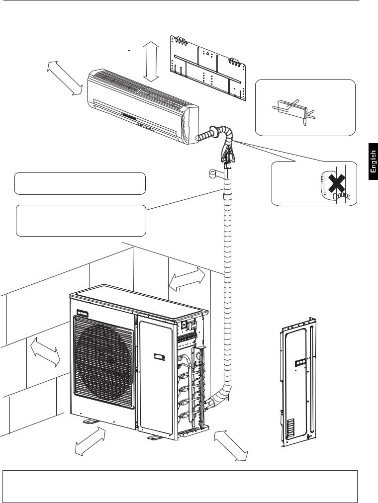
Installation drawings of indoor and outdoor units
1. Do not connected the embedded branch piping and the outdoor unit when only carrying out piping work without connecting the indoor unit in ordor to add another indoor unit later. Make sure no dirt or mositure gets into eigher side of the embedded branch piping.
2.It is impossible to connect the indoor unit for one room only.
Installation figure please refers to


More than 10cm
More than 5cm
Arrangement of piping directions
Rear left
Left |
Rear right |
Right
Below
Wrap the insulation pipe with the finishing tape 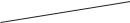
 from bottom to top.
Cut thermal insulation pipe to an appropriate length and wrap it with tape, making sure that no gap is left in the insulation pipe's cut line.
10cm than more
more |
than |
10cm |
|
||
|
|
60cm |
more |
|
than |
than |
|
more |
||
25cm |
||
|
Attention must be paid to the rising up of drain hose
If there is the danger of the unit falling or overturning, fix the unit with foundation bolts, or with wire or other means. If the location does not have good drainage, place the unit on a level mounting base(or a plastic pedestal).
Install the outdoor unit in a level position. Failure to do so may result in water leakage or accumulation.
5
Installation drawings of indoor and outdoor units
Connection cautions
model
connection priority between indoor and stop valve higher from down to up
when there is 1 indoor,the prior stop |
|
C |
|
|
D |
|
|
E |
|
|
valve is |
|
|
|
|
|
|
||||
|
|
|
|
|
|
|
|
|
||
|
|
|
|
|
|
|
|
|
|
|
when there are 2 indoors,the prior |
|
C |
B |
|
D |
C |
E |
D |
|
|
stop valves are |
|
|
|
|||||||
|
|
|
|
|
|
|
|
|
|
|
when there are 3 indoors,the prior |
C |
B |
A |
D |
C |
B |
E |
D |
C |
|
stop valves are |
||||||||||
|
|
|
|
|
|
|||||
|
|
|
|
|
|
|
|
|
|
|
when there are 4 indoors,the prior |
|
|
|
D |
C |
B A |
E D |
C |
B |
|
stop valves are |
|
|
|
|||||||
|
|
|
|
|
|
|
|
|
||
|
|
|
|
|
|
|
|
|
|
|
when there are 5 indoors,the prior |
|
|
|
|
|
E |
D |
C |
B A |
|
stop valves are |
|
|
|
|
|
|||||
|
|
|
|
|
|
|
|
|
Note: For better oil return and more reliable system, please execute as the above when connecting indoor unit.
6
Precautions on Installation
 Check the strength and level of the installation ground so that the unit will not cause any operating vibration or noise after installed.
 In accordance with the foundation drawing in fix the unit securely by means of the foundation bolts.(Prepare four sets of M8 or M10 foundation bolts, nuts and washers each which are available on the market.)
 It is best to screw in the foundation bolts until their length are 20mm from the foundation surface.
20
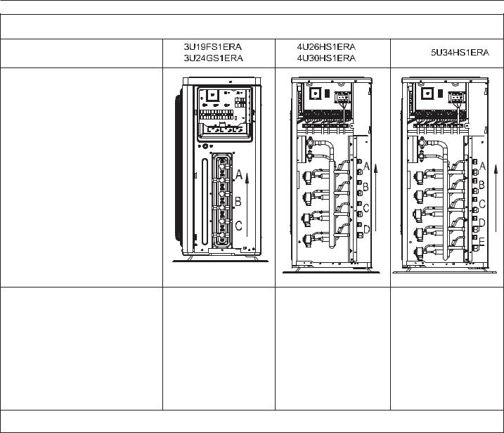
Outdoor Unit Installation Guideline
Where a wall or other obstacle is in the path of outdoor unit's intake or exhaust airflow, follow the installation guidelines below. For any of the below installation pattems, the wall height on the exhaust side should be 1200mm or less.
Wall facing one side
More than 50 |
More than 300 |
||||||||||||
|
|
|
|
|
|
|
|
|
|
|
|
|
|
|
|
|
|
|
|
|
|
|
|
|
|
|
|
|
|
|
|
|
|
|
|
|
|
|
|
|
|
|
|
|
|
|
|
|
|
|
|
|
|
|
|
1200 or less
Side view |
|
|
|
|
Wall facing two sides |
|
|
Wall facing three sides |
|
More |
More |
|
|
More than 150 |
|
|
|
||
than 100 |
than 300 |
|
|
|
|
|
|
More |
More than 300 |
More |
|
|
than 50 |
|
|
|
|
||
|
More |
|
|
|
than 100 |
|
|
|
|
Side view |
than 50 |
|
Side view |
|
|
|
|||
Limitations on the installation
1.Precautions on installation
 Check the strength and level of the installation ground so that unit will not cause any operating vibration or noise after installation.
 In accordance with the foundation drawing in fix the unit securely by means of the foundation bolts.
  It is best to screw in the foundation bolts unit their length are 20 mm from the foundation surface.
2.Selecting a location for installation of the indoor units
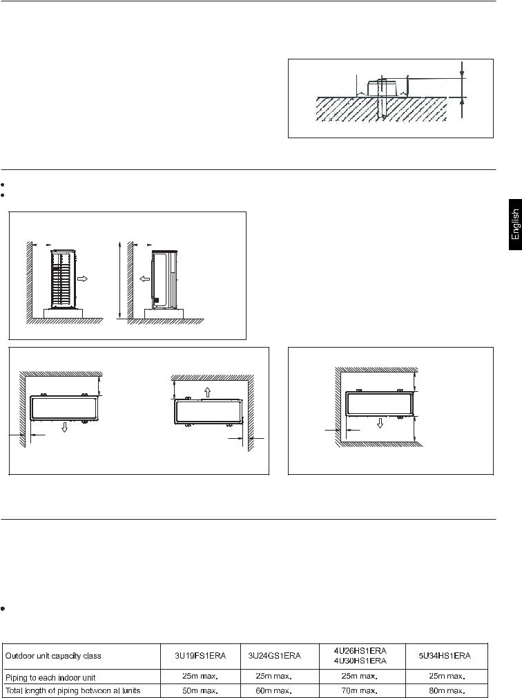
The maxinum allowable length of refrigerant piping, and the maxmum allowable height difference between the outdoor and indoor units, are listed below. (The shorter the refrigerant piping, the better the performance. Connect so that the piping is as short as possible. Shortest allowable length per room is 3m)
7

Limitations on the installation
Indoor Unit
Outdoor Unit
Level difference:
15m max. Level difference: 7.5m max.
If the outdoor unit is positioned higher than the indoor units.
Level difference: 15m max.
Level |
Outdoor Unit |
difference: |
|
7.5m max. |
|
|
Indoor Unit |
If the outdoor unit is positioned higher than the indoor units. (If lower than one or more indoor units.)
Refrigerant piping work
1.Installing outdoor unit
1)When installing the outdoor unit, refer to "Precautions for Selecting the Location" and the "Indoor/Outdoor Unit Installation Drawings". 2)If drain work is necessary, follow the procedures below.
2.Drain work
1)Use drain plug for drainage.
2)If the drain port is covered by a mounting base or floor surface, place additional foot bases of at least 30mm in height under the outdoor unit's feet.
3)In cold areas, do not use a drain hose with the outdoor unit.(Otherwise, drain water may freeze, impairing heating performance.)
Hose
Hose
Drain elbow 
Drain elbow
8
Refrigerant piping work
3. Refrigerant piping work
1). Align the centres of both flares and tighten the flare nuts 3 or 4 turns by hand. Then tighten them fully with the tor wrenches. Use torque wrenches when tightening the flare nuts to prevent damage to the flare nuts and escaping gas.
|
Flare nut fightening torque |
|
|
|
|
Flare nut for |
6.35 |
14.2-17.2N.m(144-175kgf.cm) |
Coat here with refrigeration oil |
Torque spanner |
|
Flare nut for |
9.52 |
32.7-39.9N.m(333-407kgf.cm) |
|
||
|
|
||||
Flare nut for |
12.7 |
49.5-60.3N.m(505-615kgf.cm) |
|
|
|
Flare nut for |
15.88 61.8-75.4N.m(630-769kgf.cm) |
|
Spanner |
||
|
|
|
|
|
|
Valve cap tightening torque |
Service port cap tightening torque |
|
|||
Liquid pipe 26.5-32.3N.m(270-330kgf.cm) |
|
|
Pipe joint |
||
10.8-14.7N.m(110-150kgf.cm) |
|
||||
|
|
|
Cone nut |
||
Gas pipe 48.1-59.7N.m(490-610kgf.cm) |
|
|
|||
|
|
|
|||
2)To prevent gas leakage, apply refrigeration oil on both inner and outer surfaces of the flare. (Use refrigeration oil for R410A) |
|||||
4. Purging air and checking gas leakage
When piping work is completed, it is necessary to purge the air and check for gas leakage.
 WARNING
1)Do not mix any substance other than the specified refrigerant (R410A) into the refrigeration cycle.
2)When refrigerant gas leaks occur, ventilate the room as soon and as much as possible.
3)R410A, as well as other refrigerants, should always be recovered and never be released directly into the environment.
4)Use a vacuum pump for R410A exclusively. Using the same vacuum pump for different refrigerents may damage the vacuun pump or the unit.
 If using additional refrigerant, perform air purging from the refrigerant pipes and indoor unit using a vacuum pump, then charge additional refrigerant.
 Use a hexagonal wrench (4mm) to operate the stop valve rod.
 All refrigerant pipe joints should be tightened with a torque wrench at the specified tightening torque.
Connect projection side of charging hose(Which comes from gauge manifold) to gas stop valve's service port.
Fully open gauge manifold's low-pressure valve(Lo) and completely close its high-pressure valve(Hi). (High-pressure valve subsequently requires no operation.)
Apply vacuum pumping. Check that the compound pressure gauge reads-0.1MPa(-76cmHg).
Evacuation for at lease 1 hour is recommended.
Close gauge manifold's low-pressure valve(Lo) and stop vacuum pump.
(Leave as is for 4-5 minutes and make sure the coupling meter needie does not go back.
If it does go back, this may indicate the presence of moisture or leaking from connecting parts. After inspecting all the connection and loosening then retightening thenuts, reqeat steps 2-4. )
Remove covers from liquid stop valve and gas stop valve.
Turn the liquid stop valve's rod 90 degrees counterclockwise with a hexagonal wrench to open valve. Close it after 5 seconds, and check for gas leakage.
Using soapy water, check for gas leakage from indoor unit's flare and outdoor unit's flare and valve rods. After the check is complete, wipe all soapy water off.
Disconnect charging hose from gas stop valve's service port, then fully open liquid and gas stop valves. (Do not attempt to turn valve rodj beyond its stop.)
Tighten valve caps and service port caps for the liquid and gas stop valves with a torque wrench at the specified torques. See "3 Refrigerant piping " on page 6 for details.
9

Refrigerant piping work
5. Refilling the refrigerant
Check the type of refrigerant to be used on the machine namiplate.
Precautions when adding R410A
Fill from the liquid pipe in liquid form.
It is a mixed refrigerant, so adding it in gas form may cause the refrigerant composition to change, preventing normal operation.
1) Before filling, check whether the cylinder has a siphon attached or not.(It should have something like "liquid filling siphon attached" displayed on it.)
Filling a cylinder with an attached siphon
Stand the cylinder upright when filling.
There is a siphon pipe inside, so the cylinder need not be upside-down to fill with liquid.
Filling other cylinders
Turn the cylinder upside-down when filing.
2) Be sure to use the R410A tools to ensure pressure and to prevent foreign objects entering.
6. Charging with refrigerant
1) This system must use refrigersant R410A.
2) Add refrigerant 20g per meter when the total piping length exceeds the standard value, but make sure that the total liquid piping length should be less than the max. value.
Notes:
1)When using this product, you need not to set the address. But the L/N wires between indoor & outdoor units must be corresponded, or there will be communication failure.
2)Quiet Operation Setting. Set the DIP "8" to ON position of SW5, the system will run with lower noise, but the max. capacity will also reduce slightly.
3)Do not change the settings of other switchs, wrong settings can make the system damage or other malfunctions.
7.Precautions for Laying Refrigerant Piping  Cautions on pipe handling
1)Protect the open end of the pipe against dust and moisture.
2)All pipe bends should be as gentle as possible. Use a pipe bender for bending.(Bending radius should be 30 to 40mm or larger.)
 Selection of copper and heat insulation materials
When using commercial copper pipes and fittings, observe the following : 1) Insulation material: Polyethylene foam
Heat transfer rate: 0.041 to 0.052W/mK(0.035to 0.045kcal/mhoC) Refrigerant gas pipe's surface temperature reaches 110oC max. Choose heat insulation materials that will withstand this temperature.
2) Be sure to insulate both the gas and liquid piping and to provide insulation dimensions as below.
Gas pipe |
Gas pipe insulation |
O.D.:9.52mm,12.7mm |
I.D.:12-15mm,12.7mm |
Thickness:0.8mm |
Thickness:13mm min. |
Liquid pipe |
Liquid pipe insulation |
|
|
O.D.:6.35mm |
I.D.:18-10mm |
Thickness:0.8mm |
Thickness:10mm min. |
10

Refrigerant Piping Work
3) Use separate thermal insulation pipes for gas and liquid refrigerant pipe.
|
Inter unit wiring |
|
Be sure to |
Wall |
|
Gas pipe |
|
|
|
|
|
|
|
Liquid pipe |
place a cap. |
|
|
|
|
|
|
|
|
|
|
|
|
Rain |
|
|
|
|
|
If no flare cap is |
|
|
|
|
|
available, cover the |
|
Gas pipe |
|
|
Liquid pipe |
flare mouth with tape |
|
|
|
to keep dirt or water |
|
||
insulation |
|
|
insulation |
|
|
|
|
out. |
|
||
Finishing tape |
Drain hose |
|
|
||
|
|
|
|
||
|
Check |
|
|
|
|
Flare's inner |
|
The pipe end |
|
|
|
surface must be |
|
|
|
||
|
must be evenly |
|
|
||
flaw-free. |
|
|
|
||
|
flared in a perfect |
|
|
||
|
|
Cut exactly at right |
Remove burrs |
||
|
|
circle. |
|
||
|
|
|
angles. |
|
|
|
|
|
|
|
|
|
|
Make sure that the |
|
|
|
|
|
flare nut is fitted. |
|
|
|
Set exactly at the position shown below.
A |
Flare tooling die |
Flare tool for R410A |
|
Conventional flare tool |
Clutch-type |
Clutch-type(Rigid-type) Wing-nuttype(Imperial-type) |
|
0-0.5mm |
1.0-1.5mm |
1.5-2.0mm |
|
|
|
8.Cutting and Flaring work of piping
 Pipe cutting is carried out with a pipe cutter and burs must be removed.
 After inserting the flare nut, flaring work is carried out.
A |
Pipe |
Pipe diameter |
Size A (mm) |
|
Liquid side |
6.35mm(1/4") |
0.8~1.5 |
||
|
||||
|
|
9.52mm(3/8") |
1.0~1.5 |
|
Flare tooling die |
Gas side |
12.7mm(1/2") |
1.0~1.5 |
|
|
|
Correct |
Incorrect |
Lean Damage of flare Crack |
Partial Too outside |
9. On drainage
 Please install the drain hose so as to be downward slope without fail. Please don't do the drainage as shown below.
|
|
|
Less than |
|
|
|
|
5cm |
|
It becomes high |
The end is immersed |
|
It gap with the ground its |
There is the bad |
midway. |
in water |
It waves. |
too small. |
smell from a ditch. |
 Please pour water in the drain pan of the indoor unit, and confirm that drainage is carried out serely to outdoor.
 In case that the attached drain hose is in a room, please apply heat insulation to it without fail.
 WARNING
1)Do not use mineral oil on flared part.
2)Prevent mineral oil from getting into the system as this would educe the lifetime of the units.
3)Never use piping which has been used for previous installations. Only use parts which are delivered with the unit.
4)Do never install a drier to this R410A unit in order to guarantee its lifetime.
5)The drying material may dissolve and damage the system.
6)Incom;ete flaring may cause refrigerant gas leakage.
11

Pump Down Operation
In order to protect the environment, be sure to pump down when relocating or disposing of the unit.
1)Remove the valve caps from liquid stop valve and gas stop valve.
2)Carry out forced cooling operation.
3)After five to ten minutes, close the liquid stop valve with a hexagonal wrench.
4)After two to three minutes, close the gas stop vaile and stop forced cooling operation.
liquid
stop valve Hexagonal wernch
Close
Gas
stop valve
Valve cap
Wiring work
1. Electric wiring
 The air conditioner must use special circuit , and wiring by the qualified electrician according to the wiring rules specified in national standard.
 The grounding wire and the neutral wire shall be strictly separated. Connect the neutral wire with grounding wire is incorrect.
 The electric leakage breaker must be installed.
 All the electric wire must be copper wire.Power supply:


 The wiring method of power line is Y connection. If the power line is damaged, in order to avoid risk of electric shock, it must be replaced by the manufacturer or its repair center or other similar qualified person.The connecting cable must be shielded.
Fuse: T3.15A 250VAC T16A 250VAC (Please check with the outdoor unit wiring diagram.)  Please check the circuit diagram about the fuse replaced.
2. Wiring method |
|
|
|
Wiring method of orbicular terminals |
|
|
|
For the connection wire with orbicular terminals, its wiring method is as shown in |
|
||
the right figure: remove the connecting screw, put the screw through the ring on |
|
||
the end of the wire, then connect to the terminal block and fasten screw. |
|
||
Wiring method of straight terminals. |
|
Wiring Method for |
|
For the connection wire without orbicular terminals, its wiring method is: loosen |
Ring Terminal Block |
||
|
|||
the connection screw, and insert the end of the connection wire completely into |
|
||
the Terminal block, then fasten the screw. |
Correct Pressing |
Wrong Pressing |
|
Slightly pull the wire outwards to confirm it is firmly held. |
|
||
|
|
|
Terminal |
Crimp connection method for wires without terminals |
|
block |
|
Connect the wire with |
Do not connect the |
Do not connect the |
|
same diameter to the |
wire with same diameter |
wire with different |
Pressing |
two sides of the terminal |
to the same side |
diameters |
Clamps |
 Crimp connection method for connection wire
After connection,the wire must be fastened by wire cover. The wire cover shall press on the protection coat of the connection wire,as shown in right top figure.
Note:When connecting the wiring,confirm the terminal number of indoor and outdoor units carefully. Incorrect wiring will damage the controller of air conditioner or the unit can not operate.
3. Wiring method of outdoor unit:
 Power line
Remove the repair board of the outdoor unit and loosen the wire cover A,then put the live wire, neutral wire and grounding wire through the wire cover ,and connect them to terminal block correspon dingly. After connection, fasten wire cover to its previous state. Communication wire of indoor unit.
 Loosen wire cover , put the communication wire through the wire cover B, and connect them to terminal block correspondingly. After connection, fasten wire cover B to its previous state.
Note: Power line and communication wire are provided by consumers themselves.
12

Wiring work
Wire cover A |
Wire cover C |
Wire cover A Wire cover C |
Terminal block |
|
|
|
|
||
|
|
Wire cover B |
Wire cover D |
|
Wire cover B Terminal block |
|
Wire cover E |
||
Valve cover |
|
Valve cover |
|
|
4. Wiring method of indoor unit
Loosen wire cover and connect the power line and communication wire of indoor unit to the terminal correspondingly.
Note:
When connecting power line to power supply terminal, please pay attention to the following items:
 Do not connect the power line with different dimensions to the same connection wire end. Improper contact will cause heat generation.
 Do not connect the power line with different dimensions to the same grounding wire end. Improper contact will affect protection.
 Do not connect the power line to the connecting end of communication wire. Incorrect connection will cause damage to the connected unit.
5. Example wiring diagram.
Wiring diagram please refers to


13
Test running
 Before starting the test running, please confirm the following works have been done successfully.
1)Correct piping work;
2)Correct wiring work;
3)Correct match of indoor and outdoor unit;
4)Proper recharge of refrigerant if needed.
 Make sure that all the stop valves are fully open.
 Check the voltage supplied to the outdoor and indoor units, please cinfirm that is 230V.
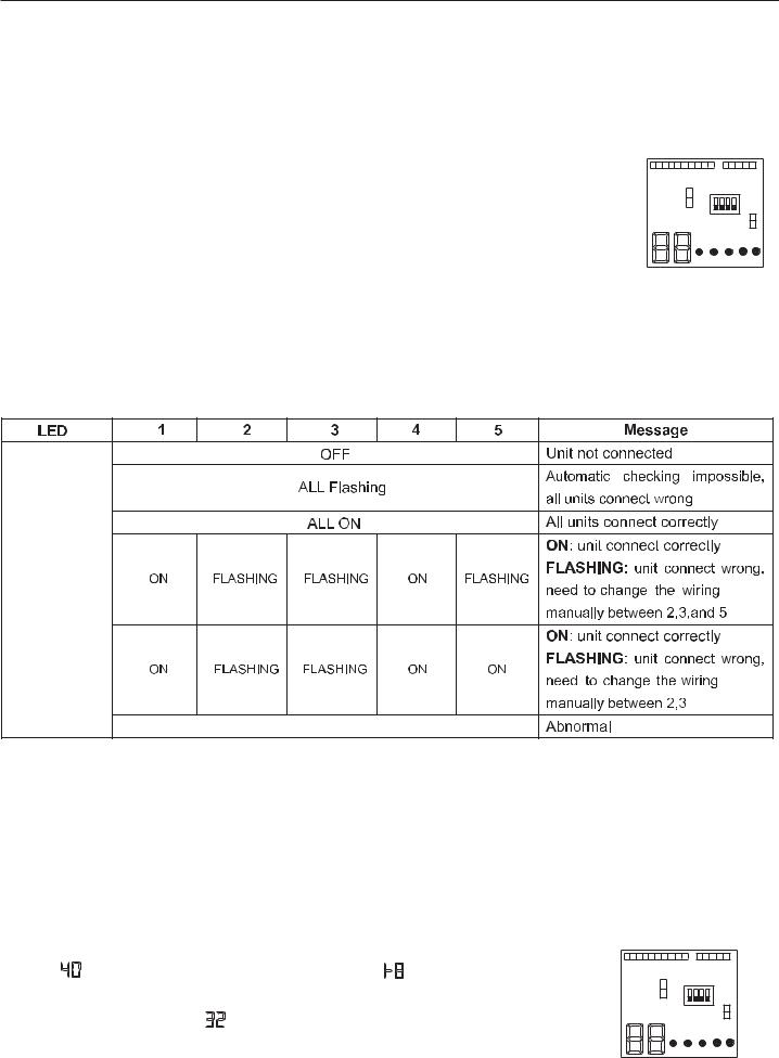
 Wiring Error Check
This product is capable of automatic checking of wiring error.
Switch on all the 4 dip-switches on the outdoor unit small service PC-board as shown on the right. Then power off the unit and power on again, the system will enter the operation of "Wiring Error Check". After 3 minutes stand-by, the unit starts for automatic wiring checking.
Approximately 30 ~ 50minutes (depends on how many units installed in the system) after the unit starts, the Errors of the wiring will be shown by the LEDs (1 to 5).
CN2 |
|
|
CN3 |
|
CN4 |
ON |
|
SW1 |
|
|
|
|
|
|
|
1 2 3 4 |
|
||
|
|
|
CN1 |
|
1 |
2 |
3 |
4 |
5 |
During this operation, the digital-number will alternately show the compressor working frequency (e.g. 50 stands for the current running frequency) and letter "CH"(means checking).
After this operation, if all the wiring is correct, the digital-number will show "0", if there has wrong wiring, the digital-number will show "EC"(error connection) and also it will flashing.
The service monitor LEDs indicate the error of wiring, as shown in the table below. For details about how to read the LED display, refer to the service manual.
If self-checking is not possible, check the indoor unit wiring and piping in the usual manner.
Status |
Only one LED flashing |
 Test running.
1)If the temperature is lower than 16 OC, it is impossible to test cooling with remote controller, and also when the temperature is higher than 30 OC, it is impossible to test heating.
2)To test cooling, set the lowest temperature at 16 OC. To test heating,set the highest temperature, at 30 OC.
3)Please check both cooling and heating operation of each unit individually and then also check the simultaneous operation of all indoor units.
4)After ruuning the unit for about 20 minutes, check the indoor unit outlet temperature.
5)After the unit is stopped, or working mode changed, the system will not start again for about 3 minutes.
6)During cooling operation, frost may ocur on the indoor unit or pipes, this is normal.
7)Operate the unit according to the operation manual. Please kindly explain to our customers how to operate through the instruction manual.
 Seven-segment numeric display
1) When unit is runing, this seven-segment numeric will display the frequency of compressor. For example," " means compressor running frequency is 40 Hz, " " means compressor running frequency is 108Hz.
2) When faulty happens, seven-segment numeric will flash and display some numbers, this number is failure code. For example, a flashing " " means No.32 failure, that is indoor and outdoor communication error.
 Communication LED
CN2 |
|
|
CN3 |
|
CN4 |
ON |
|
SW1 |
|
|
|
|
|
|
|
1 2 3 4 |
|
||
|
|
|
CN1 |
|
1 |
2 |
3 |
4 |
5 |
5 green LED means 5 indoor units. If one LED keep lighting that means the corresponding indoor unit has good communication with outdoor unit. If one LED is not lighting, that means there is no communication between indoor and outdoor.
14

Trouble shooting
Possible reasons |
|
Outdoor LED |
Wired |
Cassette and convertible |
||
|
|
|
display |
controller |
indoor display outdoor error |
|
|
|
|
|
display |
code use the timer and runing |
|
|
|
|
|
|
lamp |
|
|
|
|
|
|
|
|
|
|
|
|
|
Timer lamp |
Running lamp |
|
|
|
|
|
flash time |
flash time |
Faulty of outdoor unit EEPROM |
1 |
15 |
2 |
1 |
||
IPM overcurrent or short circuit |
2 |
16 |
2 |
2 |
||
Communication failure between Module and ECU |
4 |
18 |
2 |
4 |
||
Communication cables broken or not well connected. |
|
|
|
|
||
Module operated overload |
5 |
19 |
2 |
5 |
||
Module low or high DC voltage(under 192V or above |
6 |
1A |
2 |
6 |
||
375V) |
|
|
|
|
|
|
Discharging temperature overheating.Lack of refrigerant, |
8 |
1C |
2 |
8 |
||
ambient temperature too high or PMVs blocked. |
|
|
|
|
||
Malfunction of the DC fan motor |
9 |
1D |
2 |
9 |
||
Malfunction of defrosting temp. sensor |
10 |
1E |
3 |
0 |
||
Malfunction of compressor suction temp. sensor |
11 |
1F |
3 |
1 |
||
Malfunction of ambient temp. sensor |
12 |
20 |
3 |
2 |
||
Malfunction of compressor discharge temp. sensor |
13 |
21 |
3 |
3 |
||
Communication failure between indoor&outdoor unit |
15 |
23 |
3 |
5 |
||
Lack of refrigerant or discharging pipe blocked |
16 |
36 |
3 |
6 |
||
4-way valve switching failure |
17 |
25 |
3 |
7 |
||
Module overcurrent /Module switch failure |
18 |
26 |
3 |
8 |
||
Indoor overload |
|
|
20 |
28 |
4 |
0 |
Indoor frosted |
|
|
21 |
29 |
4 |
1 |
Module temperature too high (Overload Protecter) |
23 |
2B |
4 |
3 |
||
Compressor overcurrent |
24 |
2C |
4 |
4 |
||
Input overcurrent |
|
25 |
2D |
4 |
5 |
|
MCU reset |
|
|
26 |
2E |
4 |
6 |
Module current detect circuit malfunction |
27 |
2F |
4 |
7 |
||
Malfunction of liquid pipe temp. sensor for indoor unit A |
28 |
30 |
4 |
8 |
||
Malfunction of liquid pipe temp. sensor for indoor unit B |
29 |
31 |
4 |
9 |
||
Malfunction of liquid pipe temp. sensor for indoor unit C |
30 |
32 |
5 |
0 |
||
Malfunction of liquid pipe temp. sensor for indoor unit D |
31 |
33 |
5 |
1 |
||
Malfunction of |
gas |
pipe temp. sensor for indoor unit A |
32 |
34 |
5 |
2 |
Malfunction of |
gas |
pipe temp. sensor for indoor unit B |
33 |
35 |
5 |
3 |
Malfunction of |
gas |
pipe temp. sensor for indoor unit C |
34 |
36 |
5 |
4 |
Malfunction of |
gas |
pipe temp. sensor for indoor unit D |
35 |
37 |
5 |
5 |
Malfunction of |
gas |
pipe temp. sensor for indoor unit E |
36 |
38 |
5 |
6 |
Malfunction of module temp.sensor |
38 |
3A |
5 |
8 |
||
Malfunction of condensing temp. sensor |
39 |
3B |
5 |
9 |
||
Malfunction of liquid pipe temp. sensor for indoor unit E |
40 |
3C |
6 |
0 |
||
Malfunction of piping temp. sensor |
41 |
3D |
6 |
1 |
||
System high pressure switch off |
42 |
3E |
6 |
2 |
||
System low pressure switch off |
43 |
3F |
6 |
3 |
||
System high pressure protection.Refrigerant |
44 |
40 |
6 |
4 |
||
overabundance,High condensing temp. or |
|
|
|
|
||
malfunction of fan motor. |
|
|
|
|
||
|
|
|
|
|
||
System low pressure protection.Refrigerant shortage, |
45 |
41 |
6 |
5 |
||
Low defrosting temp., or malfunction of fan motor. |
|
|
|
|
||
Malfunction of module temp.sensor |
46 |
42 |
6 |
6 |
||
15


MANUAL DE INSTALACIÓN DEL APARATO DE AIRE ACONDICIONADO DE TIPO MULTISPLIT
Contenido
Precauciones de seguridad ---------------- |
3 |
Accesorios ------------------------------------ |
4 |
- |
|
Precauciones para seleccionar la |
|
ubicación---------------------------------------- 4 Esquemas de instalación de las
unidades - |
|
interior y exterior ------------------------------ |
5 |
Precauciones a la hora de realizar instalación -------------------------------------- 7
Guía de instalación de la unidad
exterior ------------------------------------------ 7
Limitaciones en la instalación ------------- |
7 |
- |
|
Acometida de los tubos de |
|
refrigerante ------------------------------------- |
7 |
Funcionamiento de la bomba de
vacío -------------------------------------------12
Cableado -------------------------------------- |
12 |
- |
14 |
Prueba del aparato-------------------------- |
|
- |
15 |
Resolución de problemas ----------------- |
-
Español
Lea detenidamente este manual antes de instalar el aparato.
Guarde este manual de uso para futuras consultas.

Haier Industrial Park, No.1 Haier Road, Qingdao, República Popular China
CONFORMIDAD DE LOS MODELOS SEGÚN LAS NORMATIVAS EUROPEAS
CE
Todos los productos cumplen los requisitos de las siguientes normas europeas:
-Directiva de baja tensión 73/23/CEE
-Directiva de baja tensión 2006/95/CE
-Compatibilidad electromagnética 89/336/CEE
-Compatibilidad electromagnética 2004/108/CE
ROHS
Los productos cumplen los requisitos de la directiva 2002/95/ CEE establecida por el Parlamento Europeo y el Consejo sobre la Restricción del uso de determinadas sustancias peligrosas en aparatos eléctricos y electrónicos (Directiva RoHS de la Unión Europea).
WEEE
De acuerdo con la directiva 2002/96/CE del Parlamento Europeo, se informa al consumidor acerca de los requisitos que han de cumplirse para deshacerse de productos eléctricos y electrónicos.
REQUISITOS DE DESECHO:
Su aparato de aire acondicionado ha sido marcado con este símbolo que significa que los productos de tipo eléctrico y electrónico
no deben mezclarse con la basura doméstica sin clasificar. No intente desmontar el sistema
por sí mismo: tanto el desmontaje del sistema de aire acondicionado como la manipulación del refrigerante, el aceite y cualquier otro componente deben ser llevados a cabo por un instalador cualificado, de acuerdo con la
legislación local y nacional aplicable. Los aparatos de aire acondicionado deben ser tratados en instalaciones de manipulación especializadas para su reutilización, reciclado y recuperación. Al garantizar la correcta eliminación de este producto, estará contribuyendo a evitar las posibles consecuencias negativas que podría provocar sobre el medioambiente y la salud humana. Póngase en contacto con el instalador o la autoridad local pertinente si desea obtener más información. Las pilas deben ser extraídas del mando a distancia y eliminadas de forma independiente, de acuerdo con la legislación local y nacional aplicable.
INFORMACIÓN IMPORTANTE ACERCA DEL REFRIGERANTE UTILIZADO
Contiene gases fluorados de efecto invernadero regulados por el Protocolo de Kioto.
Kg
Kg
Kg
Este producto contiene gases fluorados de efecto invernadero regulados por el Protocolo de Kioto. No los libere a la atmósfera. Tipo de refrigerante: R410A
Valor GWP*: 1975 1975
GWP = Potencial de contribución al calentamiento global Escriba con tinta indeleble:
•1 La carga de refrigerante que contiene el producto de fábrica
•2 La cantidad de refrigerante adicional cargada in situ y
•1+2 La carga total de refrigerante en la etiqueta de refrigerante suministrada con el producto. Una vez escritos los datos correspondientes, la etiqueta deberá adherirse cerca de la conexión de carga del producto (por ejemplo, sobre la parte interna de la cubierta de la válvula de retención).
A Contiene gases fluorados de efecto invernadero regulados por el Protocolo de Kioto.
B Carga de refrigerante que contiene el producto de fábrica: consulte la placa de características de la unidad.
C Cantidad de refrigerante adicional cargada in situ. D Carga total de refrigerante.
E Unidad exterior.
F Botella de refrigerante y analizador para carga.
Precauciones de seguridad
•Lea estas precauciones de seguridad atentamente para garantizar la correcta instalación del aparato.
•Este manual clasifica las precauciones en los tipos ADVERTENCIA y PRECAUCIÓN.
•Asegúrese de tener en cuenta estas instrucciones. ya que son importantes para garantizar la seguridad.
ADVERTENCIA Si no se sigue alguna de las ADVERTENCIAS es probable que se produzcan consecuencias graves, como lesiones personales o, incluso, la muerte.
PRECAUCIÓN El hecho de no seguir alguna de las PRECAUCIONES puede dar lugar a consecuencias graves.
• En este manual se utilizan los siguientes símbolos de seguridad:
Asegúrese de tener en cuenta |
Asegúrese de establecer una |
No intentar nunca. |
|
estas instrucciones. |
conexión de toma de tierra. |
||
|
|||
|
|
|
•Después de completar la instalación, pruebe la unidad para comprobar si hay errores en dicha instalación. Proporcione al usuario las instrucciones adecuadas relativas al uso y la limpieza de la unidad conforme al manual de funcionamiento.
 ADVERTENCIA
• La instalación debe ser realizada por el distribuidor u otro profesional.
Una instalación incorrecta podría provocar fugas de agua, descargas eléctricas o un incendio.
• Instale el aparato de aire acondicionado conforme a las instrucciones proporcionadas en este manual.
Una instalación incompleta podría provocar fugas de agua, descargas eléctricas o un incendio.
• Asegúrese de utilizar los componentes de instalación suministrados o especificados.
El uso de otros componentes puede hacer que la unidad quede suelta, que haya fugas de agua, descargas eléctricas o que se produzca un incendio.
• Instale el aparato de aire condicionado en una base sólida que soporte el peso de la unidad.
Una base inadecuada o una instalación incompleta puede provocar lesiones si la unidad se desprende de la base.
• Las conexiones eléctricas deben ser llevadas a cabo conforme al manual de instalación y cumpliendo las normas de cableado eléctrico nacionales y el código de práctica.
Una capacidad insuficiente o unas conexiones eléctricas incompletas pueden provocar descargas eléctricas o un incendio.
•Asegúrese de utilizar un circuito de alimentación dedicado. No utilice nunca una fuente de alimentación compartida por otro aparato.
•Para el cableado, utilice un cable lo suficientemente largo como para cubrir toda la distancia sin empalmes.
No utilice un alargador. No coloque otras cargas en la fuente de alimentación y utilice un circuito de alimentación dedicado.
(Si no sigue estas indicaciones, el funcionamiento en modo de calefacción puede ser anómalo o se pueden producir descargas eléctricas o un incendio.)
• Utilice los tipos especificados de cables para las conexiones eléctricas entre las unidades interior y exterior.
Sujete firmemente con abrazaderas los cables de interconexión de forma que sus terminales no sufran tirones producidos por fuerzas externas. Las conexiones o sujeción con abrazaderas incompletas pueden provocar sobrecalentamiento en los terminales o un incendio.
• Después de conectar todos los cables asegúrese de darles la forma adecuada para que no estén sometidos a una fuerza excesiva en las tapas o paneles eléctricos.
Instale las tapas sobre los cables. Una instalación incompleta podría provocar sobrecalentamiento en los terminales, descargas eléctricas o un incendio.
• Si ha habido fugas de refrigerante durante la instalación, ventile la habitación.
(El refrigerante produce un gas tóxico si se expone a las llamas.)
• Una vez realizada la instalación, asegúrese de que no hay fugas de refrigerante.
(El refrigerante produce un gas tóxico si se expone a las llamas.)
• Cuando se instale o cambie de ubicación el sistema, asegúrese de que no hay sustancias distintas al refrigerante especificado (R410A) en el circuito refrigerante, como por ejemplo aire.
(Cualquier presencia de aire u otra sustancia extraña en el circuito refrigerante, provocará una elevación de la presión anormal o rupturas, lo que provocará lesiones personales.)
• Durante el vaciado, detenga el compresor antes de quitar los tubos de refrigerante.
Si el compresor sigue en funcionamiento y la válvula de retención se abre durante el vaciado, el aire se succionará cuando el compresor esté en funcionamiento, lo que provocará una presión anormal en el circuito refrigerador que dará lugar a fugas e, incluso, a lesiones personales.
• Asegúrese de establecer una conexión de toma de tierra. No utilice tubos, cables, ni la toma de tierra del teléfono para conectar a tierra la unidad.
Una conexión a tierra incompleta puede provocar descargas eléctricas o un incendio. Una fuerte subida de corriente causada por rayos u otras fuentes, puede provocar daños en el aparato de aire acondicionado.
• Asegúrese de instalar un interruptor de fugas a tierra.
Si no instala un interruptor de fugas a tierra se pueden producir descargas eléctricas o un incendio.
 PRECAUCIÓN
• No instale el aparato de aire acondicionado en un lugar en el que haya peligro de exposición a fugas de gas inflamable.
Si el gas se fuga y se acumula alrededor de la unidad, se puede producir un incendio.
• Establezca los tubos de desagüe conforme a las instrucciones este manual.
Una canalización inadecuada puede provocar inundaciones.
• Apriete la tuerca abocardada conforme al método especificado utilizando una llave dinamométrica.
Si la tuerca abocardada se aprieta demasiado, podría agrietarse lo que daría lugar a fugas de refrigerante después de un largo período de uso.
• Asegúrese de proporcionar las medidas adecuadas para evitar que la unidad exterior se utilice como refugio para animales pequeños.
Los animales pequeños pueden entrar en contacto con componentes eléctricos y causar averías, humo o un incendio. Indique al cliente que mantenga limpia el área alrededor de la unidad.

Accesorios
Accesorios suministrados con la unidad exterior:
Nº |
Dibujo |
Nombre de los |
Cantidad |
Nota |
|
componentes |
|
||||
|
|
|
|
|
|
|
|
|
|
1 |
|
1 |
|
Codo de desagüe |
3 |
|
|
|
|
|
|
|
|
2 |
|
Protección de goma |
4 |
|
|
|
|
|
|
1 |
|
3 |
|
Abrazadera |
|
3 |
|
|
|
|
|
|
|
4 |
|
Adaptador (3/8 |
1/2) |
1 |
|
5 |
|
Adaptador (1/2 |
3/8) |
1 |
|
Precauciones para seleccionar la ubicación
1)Elija un lugar lo suficientemente resistente como para soportar el peso y las vibraciones de la unidad y donde el ruido de funcionamiento no se amplifique.
2)Elija una ubicación en la que el aire caliente emitido por la unidad o el ruido de funcionamiento no causen molestias a los vecinos del usuario.
3)Evite los lugares cercanos a dormitorios y dependencias similares para que el ruido de funcionamiento no ocasione problemas.
4)Debe haber un espacio suficiente en el lugar de la instalación para meter y sacar la unidad.
5)Debe haber un espacio suficiente en el lugar de la instalación para que fluya el aire y no debe haber obstáculos alrededor de la entrada y salida de aire.
6)En las proximidades del lugar de la instalación no debe existir la posibilidad de fugas de gas inflamable.
Coloque la unidad de forma que el ruido y el aire caliente emitido no molesten a los vecinos.
7)Instale las unidades, los cables de alimentación y los cables que conectan las unidades a una distancia de al menos 3 metros de equipos de televisión y radio. De esta forma se evitarán interferencias en la imagen y el sonido. (En función de las condiciones de las ondas de radio, los ruidos pueden oírse incluso si hay más de tres metros de distancia.)
8)En áreas costeras u otros lugares con atmósfera salada o gas sulfato, la corrosión puede acortar el período de vida útil del aparato de aire acondicionado.
9)Dado que el sistema de desagüe sale de la unidad exterior, no coloque nada que no resista la humedad debajo de dicha unidad.
NOTA:
No se puede instalar colgándose del techo ni apilándolo.
 PRECAUCIÓN
Cuando utilice el aparato de aire acondicionado a una temperatura ambiente exterior baja, asegúrese de seguir las instrucciones descritas a continuación.
1)Para evitar la exposición al viento, instale la unidad exterior con su lado de succión orientado hacia la pared.
2)Nunca instale la unidad exterior en una ubicación en la que el lado de succión pueda estar expuesto directamente al viento.
3)Para evitar la exposición al viento, es recomendable instalar un deflector en el lado de descarga del aire de la unidad exterior.
4)En áreas donde nieve mucho, seleccione un lugar de instalación en el que la nieve no afecte a la unidad.
•Construya una cubierta grande.
•Construya un pedestal.
Instale la unidad a una altura suficiente del suelo como para evitar que quede cubierta por la nieve.

Esquemas de instalación de las unidades interior y exterior
1.Cuando realice trabajos de conexión de tubos no conecte la derivación de tubo integrada ni la unidad exterior sin conectar antes la unidad interior para poder añadir más tarde otra unidad interior. Asegúrese de que no entra suciedad o humedad por ambos lados de la derivación integrada del tubo.
2.Es imposible conectar la unidad interior solamente para una habitación.
Consulte 


 para ver la figura de instalación
Más de 10 cm
Más de 5 cm
Organización de la dirección de los tubos
Izquierda |
Derecha trasera |
|
|
|
Derecha |
|
Debajo |
Envuelva el tubo el aislamiento con la cinta de
Corte el tubo de aislamiento térmico por la longitud adecuada y envuélvalo con cinta asegurándose de que no quedan huecos en la línea de corte del tubo de aislamiento.
|
|
cm |
|
10 |
|
de |
|
|
Más |
|
|
Más |
|
de |
|
10 |
cm |
|
cm |
Más |
|
de |
||
60 |
||
de |
25 |
|
Más |
cm |
Debe prestarse atención a la pendiente del manguito de desagüe
Si hay peligro de que la unidad se caiga, fíjela con pernos para suelo, con un cable o con otros medios.
Si la ubicación no dispone de un buen sistema de drenaje, coloque la unidad en una base de montaje nivelada (o en un pedestal de plástico).
Instale la unidad exterior en una posición nivelada. Si no sigue estas indicaciones, se pueden producir fugas o acumulación de agua.

Esquemas de instalación de las unidades interior y exterior
Precauciones para la conexión
modelo
prioridad de conexión entre la unidad interior y la válvula de retención más alta de abajo a arriba
cuando hay una unidad |
C |
D |
E |
interior, la válvula de |
|
|
|
retención previa es |
|
|
|
cuando hay 2 unidades |
C B |
D C |
E D |
interiores, las válvulas de |
|
|
|
retención previas son |
|
|
|
cuando hay 3 unidades |
C B A |
D C B |
E D C |
interiores, las válvulas de |
|
|
|
retención previas son |
|
|
|
cuando hay 4 unidades |
|
D C B A |
E D C B |
interiores, las válvulas de |
|
|
|
retención previas son |
|
|
|
cuando hay 5 unidades |
|
|
E D C B A |
interiores, las válvulas de |
|
|
|
retención previas son |
|
|
|
Nota: para mejorar el retorno del aceite y la fiabilidad del sistema, siga las indicaciones anteriores cuando conecte la unidad interior.

Precauciones a la hora de realizar instalación
•Compruebe la resistencia y el nivel de la superficie de la instalación para que la unidad no cause vibraciones o ruido durante su funcionamiento después de instalada.
•En función de los planos de los cimientos, fije la unidad de forma segura mediante los pernos para suelo. (Prepare cuatro juegos de pernos para suelo M8 o M10, tuercas y arandelas. Todos estos componentes están disponibles en el mercado.)
•Atornille los pernos para suelo hasta que se hayan introducido 20 mm.
Guía de instalación de la unidad exterior
•Siga las instrucciones de instalación que se indican a continuación cuando haya una pared u otros obstáculos en la trayectoria del flujo de aire de entrada o salida de la unidad exterior.
•Para cualquiera de los modelos de instalación siguientes, la altura de la pared del lado de la salida de aire debe ser de 1200 mm como máximo.
Pared en un lado
Más de 50 mm |
Más de 300 mm |
||||||
|
|
|
|
|
|
|
|
|
|
|
|
|
|
|
|
|
|
|
|
|
|
|
|
1200 mm  como
como
máximo
Vista lateral |
|
|
|
Pared en dos lados |
|
Pared en dos lados |
|
|
Más de |
|
Más de 150 mm |
Más de |
|
|
|
100 mm |
300 mm |
|
|
|
|
Más de |
Más de 300 mm |
Más de |
|
50 mm |
|
|
|
|
|
100 mm |
|
Más de |
|
Vista lateral |
50 mm |
Vista lateral |
|
Limitaciones en la instalación
1.Precauciones a la hora de realizar la instalación
•Compruebe la resistencia y el nivel de la superficie de la instalación para que la unidad no cause vibraciones o ruido durante su funcionamiento después de instalada.
•En función de los planos de los cimientos, fije la unidad de forma segura mediante los pernos para suelo.
•Atornille los pernos para suelo hasta que se hayan introducido 20 mm.
2.Seleccionar una ubicación para la instalación de las unidades interiores
•A continuación se muestran la longitud máxima permitida de los tubos de refrigerante y la diferencia de altura máxima permitida entre la unidad exterior y las unidades interiores. Cuanto más cortos sean los tubos de refrigerante, mayor será el rendimiento. Por tanto, realice las conexiones de forma que los tubos sean tan cortos como sea posible. La longitud más corta permitida por habitación es de 3 m.
Clase de capacidad de la unidad exterior |
|
|
|
|
|
|
|
|
|
Tubos a cada unidad interior |
máximo. |
máximo. |
máximo. |
máximo. |
|
|
|
|
|
Longitud total de los tubos entre todas las unidades |
máximo. |
máximo. |
máximo. |
máximo. |
|
|
|
|
|
 Loading...