


ROOM AIR CONDITIONER
INSTALLATION MANUAL
1U07BS1ERA
1U09BS1ERA
1U12BS1ERA
1U18FS1ERA
1U24GS1ERA
Contents
Indoor/Outdoor Unit Installion Drawings |
1 |
Safety Precautions |
2 |
Read Before Installation |
6 |
Installation Procedure |
9 |
Outdoor Unit Troubleshooting |
14 |
Contenido
Unidad interior y exterior Dibujos de extracción |
15 |
Precauciones de seguridad |
16 |
Leer antes de realizar la instalación |
20 |
Procedimiento instalación |
23 |
Unidad interior Resolución de problemas |
28 |
Indice
Unità esterna/interna Immagini per l'installazione |
29 |
Precauzioni di sicurezza |
30 |
Leggere prima dell'installazione |
34 |
Processo di installazione |
37 |
Unità esterna Risoluzione dei problemi |
42 |
Table des matières
Unité intérieure/extérieure Schémas d'installation |
43 |
Consignes de sécurité |
44 |
À lire avant l'installation |
48 |
Procédure d'installation |
51 |
Unité extérieure Dépannage |
56 |
●Please read this manual carefully before installtion.
Keep this operation manual for future reference.
NO.0010535386

Haier Industrial Park, No.1 Haier Road, Qingdao, P.R.China
EUROPEAN REGULATIONS CONFORMITY FOR THE MODELS
CE
All the products are in conformity with the following European provision:
-Low Voltage Directive 73/23/EEC
-Low Voltage Directive 2006/95/EC
-Electomagnetic CompatibilitY 89/336/EEC
 -Electomagnetic CompatibilitY 2004/108/EC
ROHS
The products are fulfilled with the requirements in the directive 2002/95/EEC of the European parliament and of council on the Restriction of the use of Certain Hazardous Substances in Electrical and Electronic Equipment (EU RoHS Directive)
WEEE
In accordance with the directive 2002/96/CE of the European parliament, herewith we inform the consumer about the disposal requirements of the electrical and electronic products.
DISPOSAL REQUIREMENTS:
Your air conditioning product is marked with this  symbol.This means that electrical and electronic
products shall not be mixed with unsorted
household waste. Do not try to dismantle the system yourself : the dismantling of the air
conditioning system,treatment of the refrigerant, of oil and of other part must be done by a qualified installer in accordance with relevant local and national legislation. Air conditioners must be treated at a specialized treatment facility for reuse, recycling and recovery. By ensuring this product is disposed of correctly, you will help to prevent potential negative consequences for the environment and humen health. Please contact the installer or local authority for more information. Battery must be removed from the remote controller and disposed of separately in accordance with relevant local and nationl legislation.
IMPORTANT INFORMATION REGARDING THE REFRIGERANT USED
Contains fluorinated greenhouse gases |
|
|||
covered by the Kyoto Protocol |
|
A |
||
R410A |
1= |
kg |
B |
|
2 |
1 |
2= |
kg |
C |
|
|
|
||
|
|
|
|
|
|
|
1+2= |
kg |
D |
|
|
|
|
|
F |
E |
|
|
|
This product contains fluorinated greenhouse gases covered by the Kyoto Protocol. Do not vent into the atmosphere. Refrigerant type:R410A
GWP* value:1975
GWP=global warming potential
Please fill in with indelible ink,
•1 the factory refrigerant charge of the product
•2 the additional refrigerant amount charged in the field and
•1+2 the total refrigerant charge
on the refrigerant charge label supplied with the product. The filled out label must be adhered in the proximity of the product charging port (e.g. onto the inside of the stop value cover).
A contains fluorinated greenhouse gases covered by the Kyoto Protocol
B factory refrigerant charge of the product: see unit name plate
C additional refrigerant amount charged in the field D total refrigerant charge
E outdoor unit
F refrigerant cylinder and manifold for charging

Indoor/Outdoor Unit Installation Drawings
The models adopt HFC free refrigerant R410A.
For installation of the indoor units,refer to the installation manual which was provided with the units. (The diagram shows a wall-mounted indoor unit.)
more than 15cm
more than 10cm
Arrangement of piping directions
|
Rear left |
Left |
Rear |
|
right |
Right
Below
more than 20cm
The marks from A to G in the figure are the parts numbers.
The distance between the indoor unit and the floor should be more than 2m.
more than 60cm 
Attention must be paid to the rising up of drain hose
G
more than 10cm
F
A
C
more than 20cm 

 D
D
E
Optional parts for piping
A |
Non-adhesive tape |
B |
Adhesive tape |
C Saddle (L.S) with screws |
|
D |
Connecting electric cable |
for indoor and outdoor |
|
E |
Drain hose |
F |
Heating insulating material |
G Piping hole cover
Fixing of outdoor unit
Fix the unit to concrete or block with bolts (10mm) and nuts firmly and horizontally.
When fitting the unit to wall surface, roof or rooftop, fix a supporter surely with nails or wires in consideration of earthquake and strong wind. If vibration may affect the
house, fix the unit by attaching a vibration-proof mat.
more than 25cm
 AIR OUTLET
 AIR INLET
 CONNECTING PIPING AND ELECTRICAL WIRING


 4 DRAIN HOSE
Compressor(Inside of Unit)
The above indoor and outdoor units’ picture is just for your reference.
Please be subject to the actual product purchased.
1

 WARNING
 CAUTION
2 |

Safety Precautions
 WARNING
Have the unit professionally installed. |
Be sure to carefully follow each step in this handbook when |
|
|
Improper installation by an unqualified person may result |
installing the unit. |
|
|
in water leak, electric shock, or fire. |
Improper installation may result in water leak, electric shock, |
|
|
|
smoke or fire. |
|
|
Place the unit on a stable, level surface that withstands the |
|
|
|
weight of the unit to prevent the unit from tipping over or |
Have all electrical work performed by a licensed electrician |
|
|
falling causing injury as a result. |
according to the local regulations and the instructions given |
|
|
|
in this manual. Secure a circuit designated exclusively to |
|
|
Only use specified cables for wiring. Securely connect each |
the unit. |
|
|
cable, and make sure that the cables are not straining the |
Improper installation or a lack of circuit capacity may cause |
|
|
terminals. |
the unit to malfunction or present a risk of electric shock, |
|
|
Cables not connected securely and properly may generate |
smoke,and fire. |
|
|
heat and cause fire. |
|
|
|
|
Securely attach the terminal cover(panel) on the unit. |
|
|
Take necessary safety measures against typhoons and |
If installed improperly, dust and/or water may enter the unit |
|
|
earthquakes to prevent the unit from falling over. |
and present a risk of electric shock, smoke or fire. |
|
|
Do not make any changes or modifications to the unit. In |
Only use refrigerant R410A as indicated on the unit when |
|
|
case of problems, consult the dealer. |
installing or relocating the unit. |
|
|
If repairs are not made properly, the unit may leak water |
The use of any other refrigerant or an introduction of air into |
|
|
and present a risk of electric shock, or it may produce smoke |
the unit circuit may cause the unit to run an abnormal cycle |
|
|
or cause fire. |
and abnormal cycle and cause the unit to burst. |
|
|
|
|
|
|
 WARNING
 Do not touch the fins on the heat exchanger with bare hands, for they are sharp and dangerous.
 In the event of a refrigerant gas leak, provide adequate ventilation to the room.
If leaked refrigerant gas is exposed to a heat source, noxious gases may form.
 With All-Fresh type air conditioners, outdoor air may be directly blown into the room upon thermo off. Take this into consideration when installing the unit.
Direct exposure to outdoor air may present a health hazard, and it may also cause food items to deteriorate.
 Do not try to defeat the safety features of the devices, and do not change the settings.
Defeating the safety features on the unit such as the pressure switch and temperature switch or using parts other than the dealer or specialist may result in fire or explosion.
 When installing the unit in a small room, safeguard against hypoxia that results from leaked refrigerant reaching the threshold level.
Consult the dealer for necessary measures to take.
 When relocating the air conditioner, consult the dealer or a specialist.
Improper installation may result in water leak, electric shock, or fire.
 After completing the service work, check for a refrigerant gas leak.
If leaked gas refrigerant is exposed to a heat source such as fan heater,stove,and electric grill, noxious gases may form.
 Only use specified parts.
Have the unit professionally installed. Improper installation may cause water leak, electric shock,smoke, or fire.
3
Safety Precautions
Precautions for Handling Units for Use with R410A
 Caution
Do not use the existing refrigerant piping
 The old refrigerant and refrigerator oil in the existing piping contain a large amount of chlorine, which will cause the refrigerator oil in the new unit to deteriorate.
 R410A is a high-pressure refrigerant, and the use of the existing piping may result in bursting.
Keep the inner and outer surfaces of the pipes clean and free of contaminants such as sulfur, oxides, dust/dirt shaving particles,oils,and moisture.
 Contaminants inside the refrigerant piping will cause the refrigerant oil to deteriorate.
Use a vacuum pump with a reverse-flow check valve.
 If other types of valves are used, the vacuum pump oil will flow back into the refrigerant cycle and cause the refrigerator oil to deteriorate.
Do not use the following tools that have been used with the conventional refrigerants. Prepare tools that are for exclusive use with R410A.
(Gauge manifold, charging hose, gas leak detector, reverse-flow check valve, refrigerant charge base,vacuum gauge, and refrigerant recovery equipment.)
 If refrigerant and/or refrigerant oil left on these tools are mixed in with R410, or if water is mixed with R410A, it will cause the refrigerant to deteriorate.
 Since R410A does not contain chlorine, gas-leak detectors for conventional refrigerators will not work.
 Caution
Store the piping to be used during installation indoors, and keep both ends of the piping sealed until immediately before brazing.(keep elbows and other joints wrapped in plastic.)
 If dust, dirt, or water enters the refrigerant cycle, it may cause the oil in the unit to deteriorate or may cause the compressor to malfunction.
Use a small amount of ester oil, ether oil, or alkylbenzene to coat flares and flange connections.
 A large amount of mineral oil will cause the refrigerating machine oil to deteriorate.
Use liquid refrigerant to charge the system.
 Charge the unit with gas refrigerant will cause the refrigerant in the cylinder to change its composition and will lead to a drop in performance
Do not use a charging cylinder.
 The use of charging cylinder will change the composition of the refrigerant and lead to power loss.
Exercise special care when handling the tools.
 An introduction of foreign objects such as dust, dirt or water into the refrigerant cycle will cause the refrigerating machine oil to deteriorate.
Only use R410A refrigerant.
 The use of refrigerants containing chlorine(i.e. R22) will cause the refrigerant to deteriorate.
Before Installing the Unit
 Caution
Do not install the unit in a place where there is a possibility of flammable gas leak.
 Leaked gas accumulated around the unit may start a fire.
Do not use the unit to preserve food, animals, plants, artifacts, or for other special purposes.
 The unit is not designed to provide adepuate conditions to preserve the quality of these items.
Do not use the unit in an unusual environment
 The use of the unit in the presence of a large amount of oil, steam, acid, alkaline solvents or special types of sprays may lead to a remarkable drop in performance and/or malfunction and presents a risk of electric shock, smoke, or fire.
 The presence of organic solvents, corroded gas (such as ammonia,sulfur compounds,and acid may cause gas or water leak.)
When installing the unit in a hospital, take necessary measures against noise.
 High-frequency medical equipment may interfere with the normal operation of the air conditioning unit or the air conditioning unit may interfere with the normal operation of the medical equipment
Do not place the unit on or over things that may not get wet.
 When humidity level exceeds 80% or when the drainage system is clogged, indoor units may drip water.
  Installation of a centralized drainage system for the outdoor unit may also need to be considered to prevent water drips from the outdoor units.
4

Safety Precautions
Before Installing (Relocating) the Unit or Performing Electric Work
 Caution
Ground the unit.
 Do not connect the grounding on the unit to gas pipes,water pipes, lightning rods, or the grounding terminals of telephones. Improper grounding presents a risk of electric shock, smoke, fire, or the noise caused by improper grounding may cause the unit to malfunction.
Make sure the wires are not subject to tension.
 If the wires are too taut, they may break or generate heat and/or smoke and cause fire.
Install a breaker for current leakage at the power source to avoid the risk of electric shock.
 Without a breaker for current leakage, there is a risk of electric shock, smoke or fire.
Use breakers and fuses (electrical current breaker, remote switch<switch+Type-B fuse>,molded case circuit breaker) with a proper current capacity.
 The use of large-capacity fuses, steel wire, or copper wire may damage the unit or cause smoke or fire.
Do not spray water on the air conditioners or immerse the air conditioners in water.
 Water on the unit presents a risk of electric shock.
Periodically check the platform on which is placed for damage to prevent the unit from falling.
 If the unit is left on a damaged plarform, it may topple over, causing injury.
When installing draining pipes, follow the instructions in the manual, and make sure that they properly drain water so as to avoid dew condensation.
 If not installed properly, they may cause water leaks and damage the furnishings.
Properly dispose of the packing materials.
 Things such as nails may be included in the package. Dispose of them properly to prevent injury.
 Plastic bags present a choking hazard to children. Tear up the plastic bags before disposing of them to prevent accidents.
Before the Test Run
 Caution
Do not operate switches with wet hands to avoid electric.
Do not touch the refrigerant pipes with bare hands during and immediately after operation.
 Depending on the state of the refrigerant in the system, certain parts of the unit such as the pipes and compressor may become very cold or hot and may subject the person to frost bites or burning.
Do not operated the unit without panels and safety guards in their proper places.
 They are there to keep the users from injury from accidentally touching rotating, high-tempreture or highvoltage parts.
Do not turn off the power immediately after stopping the unit.  Allow for at least five minutes before turning off the unit, otherwise the unit may leak water or experience other problems.
Do not operate the unit without air filters.
 Dust particles in the air may clog the system and cause malfunction.
5

Read Before Installation
Items to Be Checked
(1). Verify the type of refrigerant used by the unit to be serviced. Refrigerant Type: R410A
(2). Check the symptom exhibited by the unit to be serviced. Look in this service handbook for symptoms relating to the refrigerant cycle.
(3). Be sure to carefully read the safety precautions at the beginning of this document.
(4). If there is a gas leak or if the remaining refrigerant is exposed to an open flame, a noxious gas hydrofluoric acid may form. Keep workplace well ventilated.
CAUTION
 Install new pipes immediately after removing old ones to keep moisture out of the refrigerant circuit.
  Chloride in some types of refrigerants such as R22 will cause the refrigerating machine oil to deteriorate.
Necessary Tools and Materials
Prepare the following tools and materials necessary for installing and servicing the unit. Necessary tools for use with R410A(Adaptability of tools that are for use with R22 and R407C).
1. To be used exclusively with R410A ( Not to be used if used with R22 or R407C )
Tools/Materials |
Use |
Notes |
Gauge Manifold |
Evacuating,refrigerant charging |
5.09MPa on the High-pressure side. |
Charging Hose |
Evacuating, refrigerant charging |
Hose diameter larger than the concentional ones. |
Refrigerant Recovery Equipment |
Refrigerant recovery |
|
Refrigerant Cylinder |
Refrigerant charging |
Write down the refrigerant type. Pink in color at the top of the cylinder. |
Refrigerant Cylinder Charging Port |
Refrigerant charging |
Hose diameter larger than the conventional ones. |
Flare Nut |
Connecting the unit to piping |
Use Type-2 Flare nuts. |
|
|
|
2. Tools and materials that may be used with R410 with some restrictions
Tools/Materials |
Use |
Notes |
Gas leak detector |
Detection of gas leaks |
The ones for HFC type refrigerant may be used. |
Vacuum Pump |
Vacuum drying |
May be used if a reverse flow check adaptor is attached. |
Flare Tool |
Flare machining of piping |
Chages have been made in the flare machining dimension.Refer to the next page. |
Refrigerant Recovery Equipment |
Recovery of refrigerant |
May be used if designed for use with R410A. |
|
|
|
3. Tools and materials that are used with R22 or R407C that can also be used with R410A
Tools/Materials |
Use |
Notes |
Vacuum Pump with a Check Valve |
Vacuum drying |
|
Bender |
Bending pipes |
|
Torque Wrench |
Tightening flare nuts |
Only 12.70 (1/2'') and 15.88(5/8'') have a larger flare machining dimension. |
Pipe Cutter |
Cutting pipes |
|
Welder and Nitrogen Cylinder |
Welding pipes |
|
Refrigerant Charging Meter |
Refrigerant charging |
|
Vacuum Gauze |
Checking vacuum degree |
|
|
|
|
4. Tool and materials that must not used with R410A
Tools/Materials |
Use |
Notes |
Charging Cylinder |
Refrigerant Charging |
Must not be used with R410-type units. |
|
|
|
Tools for R410A must be handled with special care, and keep moisture and dust from entering the cycle.
6

Read Before Installation
Piping Materials
Types of Copper Pipes (Reference)
Maximum Operation Pressure |
Applicable Refrigerants |
3.4MPa |
R22, R407C |
4.15MPa |
R410A |
|
|
 Use pipes that meet the local standards.
Piping Materials/Radial Thickness
Use pipes made of phosphorus deoxidized copper.
Since the operation pressure of the units that use R410A is higher than that of the units for use with R22, use pipes with at least the radial thickness specified in the chart below. (Pipes with a radial thickness of 0.7mm or less may not be used.)
Size(mm) |
Size(inch) |
Radial Thickness(mm) |
Type |
6.35 |
1/4'' |
0.8t |
|
|
|
|
|
9.52 |
3/8'' |
0.8t |
Type-O pipes |
|
|
|
|
12.7 |
1/2'' |
0.8t |
|
|
|
|
|
15.88 |
5/8'' |
1.0t |
|
19.05 |
3/4'' |
1.0t |
Type-1/2H or Hpipes |
|
|
|
|
 Although it was possible to use type-O for pipes with a size of up to
  19.05(3/4") with conventional refrigerants, use type- 1/2H pipes for units that use R410A.(Type-O pipes may be used if the pipe size is
  19.05 and the radial thickness is 1.2t.)
  The table shows the standards in Japan. Using this table as a reference, choose pipes that meet the local standards.
Flare Machining (type-O and OL only)
The flare machining dimensions for units that use R410A is larger than those for units that use R22 in order to increase air tightness.
Flare Machining Dimension(mm)
External dimension of pipes |
Size |
Dimension A |
|
|
R410A |
|
R22 |
||
|
|
|
||
6.35 |
1/4" |
9.1 |
|
9.0 |
9.52 |
3/8" |
13.2 |
|
13.0 |
12.7 |
1/2" |
16.6 |
|
16.2 |
15.88 |
5/8" |
19.7 |
|
19.4 |
19.05 |
3/4" |
24.0 |
|
23.3 |
|
|
|
|
|
Dimension A
If a clutch type flare tool is used to machine flares on units that use R410A, make the protruding part of the pipe between 1.0 and 1.5mm. Copper pipe gauge for adjusting the length of pipe protrusion is useful.
Flare Nut
Type-2 flare nuts instead of type-1 nuts are used to increase the strength. The size of some of the flare nuts have also been changed.
Flare nut dimension(mm)
External dimension of pipes |
Size |
Dimension B |
|
||
R410A(Type2) |
R22(Type1) |
|
|||
|
|
|
|||
6.35 |
1/4" |
17.0 |
17.0 |
|
|
9.52 |
3/8" |
22.0 |
22.0 |
|
|
12.7 |
1/2" |
26.0 |
24.0 |
Dimension B |
|
15.88 |
5/8" |
29.0 |
27.0 |
||
|
|||||
19.05 |
3/4" |
36.0 |
36.0 |
|
|
 The table shows the standards in Japan. Using this table as a reference, choose pipes that meet the local standards.
7

8
NO


 Air outlet
Wind direction
Cushion rubber
4.Installation dimension(Unit:mm)

 *
*


9
1. 
1U07BS1ERA 1U09BS1ERA 1U12BS1ERA
1U18FS1ERA
1U24GS1ERA
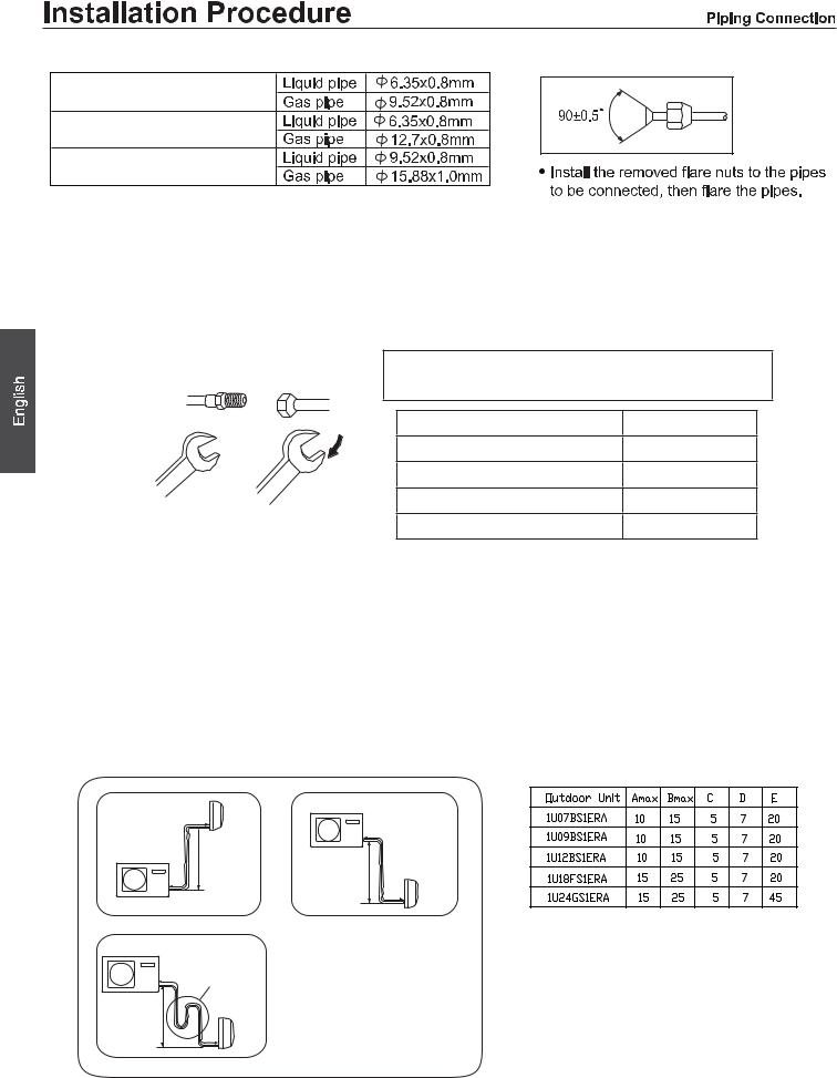
2. Connection of pipes
To bend a pipe, give the roundness as large as possible not to crush the pipe , and the bending radius should be 30 to 40 mm or longer.
Connecting the pipe of gas side first makes working easier. The connection pipe is specialized for R410A.
Half union |
Flare nut |
Forced fastening without careful centering may |
|
|
|
damage the threads and cause a leakage of gas. |
|
|
|
Pipe Diameter(ǿ) |
Fastening torque |
|
|
Liquid side6.35mm(1/4") |
18N.m |
|
|
Liquid/Gas side9.52mm(3/8") |
42 N.m |
|
|
Gas side 12.7mm(1/2") |
55N.m |
Spanner |
Torque wrench |
Gas side 15.88mm(5/8") |
60 N.m |
Be careful that matters, such as wastes of sands,water, etc. shall not enter the pipe.
CAUTION
The standard pipe length is Cm. If it is over Dm, the function of the unit will be affected. If the pipe has to be lengthened, the refrigerant should be charged, according to E g/m. But the charge of refrigerant must be conducted by professional air conditioner engineer. Before adding additional refrigerant, perform air purging from the refrigerant pipes and indoor unit using a vacuum pump,then charge additional refrigerant.
B Indoor unit
A
Outdoor unit
Outdoor unit
B |
Oil trap |
|
|
|
Indoor unit |
A
Outdoor unit
B
Indoor unit
A
●Max.Elevation: Amax
●In case the elevation A is more than 5m, oil trap shoud be installed every 5~7
●Max. Length: Bmax
●In case the pipe length B is more thanDm, the refrigerant should be charged, according to E g/m.
10

11


 (e.g.1U18FS1ERA)
12
1U07BS1ERA |
1U09BS1ERA |
1U12BS1ERA |
1U18FS1ERA |
1U24GS1ERA |
T 25A/250V. |
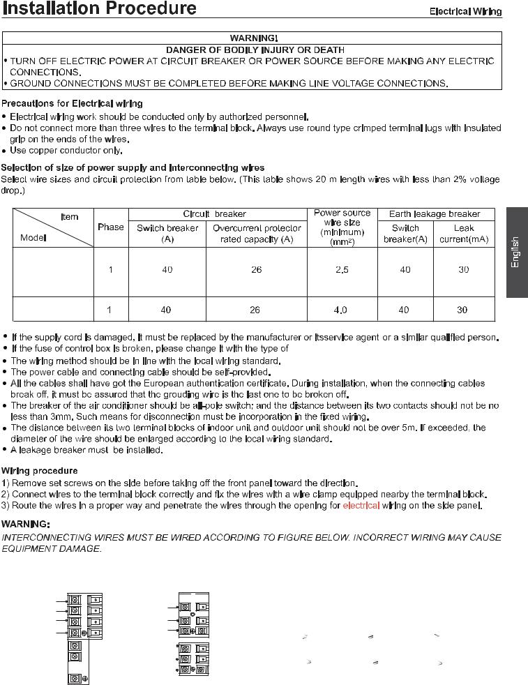
FOR 07K 09K 12K
Outdoor unit
|
N(1 |
|
) |
|
2 |
To Indoor unit |
)L( |
3 |
|
( |
|
|
C |
|
) |
|
N(1 |
|
) |
POWER |
)L(2 |
3 |
|
( |
|
^ |
C |
) |
|
|
FOR 18K 24K
Outdoor unit
 )N(1
)N(1

To Indoor unit |
)L(2 |
|
)C(3
POWER { |
L |
|
N |
||
|
Model |
1U07BS1ERA |
|
|
1U09BS1ERA |
1U18FS1ERA |
1U24GS1ERA |
|
|
1U12BS1ERA |
|
|
|
|
|
|
Connecting wiring |
4G0.75mm 2 |
4G0.75mm 2 |
4G0.75mm 2 |
|
|
|
|
Power cable |
3G1.5mm2 |
3G2.5mm2 |
3G4.0mm2 |
13

Outdoor Unit 
|
|
1 |
|
|
|
||
|
|
2 |
|
|
|
||
|
|
4 |
|
|
|
||
|
|
|
|
|
|
|
|
|
|
5 |
|
15 |
|
||
|
|
|
6 |
|
|
|
|
|
|
|
8 |
|
110 |
|
|
|
|
|
9 |
|
|
|
|
|
|
10 |
|
|
|
||
|
|
11 |
Suction temperature sensor failure |
When the The wiring of compressor is wrong or |
|
||
|
|
the connection is poor |
|
||||
|
|
|
|
|
|
|
|
12
13
15
16 |
Lack of refrigerant |
Check if there is leakage in the unit. |
m 15
17
18
19
25
25
25
Haier Group
Address:No.1 Haier Road,Hi-tech Zone,Qingdao 266101 P.R.ChiQD
Contacts: TEL +86-532-8893-6943;FAX +86-532-8893-1010
Website: www.haier.com
14
Haier Industrial Park, No.1 Haier Road, Qingdao, República Popular China
CONFORMIDAD DE LOS MODELOS SEGÚN LAS NORMATIVAS EUROPEAS
CE
Todos los productos satisfacen los requisitos de las siguientes normas europeas:
-Directiva de baja tensión, 73/23/CEE
-Directiva de baja tensión, 2006/95/CE
-Compatibilidad electromagnética 89/336/CEE
-Compatibilidad electromagnética 2004/108/CE
ROHS
Los productos satisfacen los requisitos de la directiva 2002/95/ CEE establecida por el Parlamento Europeo y el Consejo sobre restricciones a la utilización de determinadas sustancias peligrosas en aparatos eléctricos y electrónicos (Directiva RoHS UE).
WEEE
De acuerdo con la directiva 2002/96/CE del Parlamento Europeo, se informa al consumidor acerca de los requisitos de eliminación de productos eléctricos y electrónicos.
REQUISITOS DE ELIMINACIÓN:
Su aparato de aire acondicionado ha sido marcado con este símbolo, el cual significa que los productos de tipo eléctrico y electrónico
no deben mezclarse con residuos domésticos sin clasificar. No intente desmontar el sistema
personalmente: tanto el desmontaje del sistema de aire acondicionado como la manipulación del refrigerante, el aceite y cualquier otro componente deben ser llevados a cabo por un instalador capacitado, de acuerdo con la
legislación local y nacional al efecto. Los aparatos de aire acondicionado deben ser manipulados en instalaciones de manipulación especializadas y aptas para su reutilización, reciclado y recuperación. Al garantizar la correcta eliminación de este producto, usted contribuirá a evitar las posibles consecuencias negativas que podría provocar sobre el medioambiente y la salud humana. Póngase en contacto con el instalador o la autoridad local pertinente si desea obtener más información. Las pilas deben ser extraídas del mando a distancia y eliminadas de forma
independiente, de acuerdo con la legislación local y nacional al efecto.
INFORMACIÓN IMPORTANTE ACERCA DEL REFRIGERANTE UTILIZADO
Contiene gases fluorados de efecto invernadero |
|
|||
regulados por el Protocolo de Kioto. |
|
A |
||
R410A |
1= |
kg |
B |
|
2 |
1 |
2= |
kg |
C |
|
|
|
||
|
|
|
|
|
|
|
1+2= |
kg |
D |
|
|
|
|
|
F |
E |
|
|
|
Este producto contiene gases fluorados de efecto invernadero regulados por el Protocolo de Kioto. No los libere libremente a la atmósfera.
Tipo de refrigerante: R410A Valor GWP*: 1975
GWP = Potencial de contribución al calentamiento global Escriba con tinta indeleble:
•1 la carga de refrigerante que contiene el producto de fábrica
•2 la cantidad de refrigerante adicional cargada durante la instalación y
•1+2 la carga total de refrigerante
en la etiqueta de carga de refrigerante suministrada con el producto.
Una vez escritos los datos correspondientes, la etiqueta deberá adherirse cerca de la conexión de carga del producto (por ejemplo, sobre la parte interna de la cubierta de la válvula de retención).
A Contiene gases fluorados de efecto invernadero regulados por el Protocolo de Kioto.
B Carga de refrigerante que contiene el producto de fábrica: consulte la placa de características de la unidad.
C Cantidad de refrigerante adicional cargada durante la instalación. D Carga total de refrigerante.
E Unidad exterior.
F Botella de refrigerante y colector de carga.

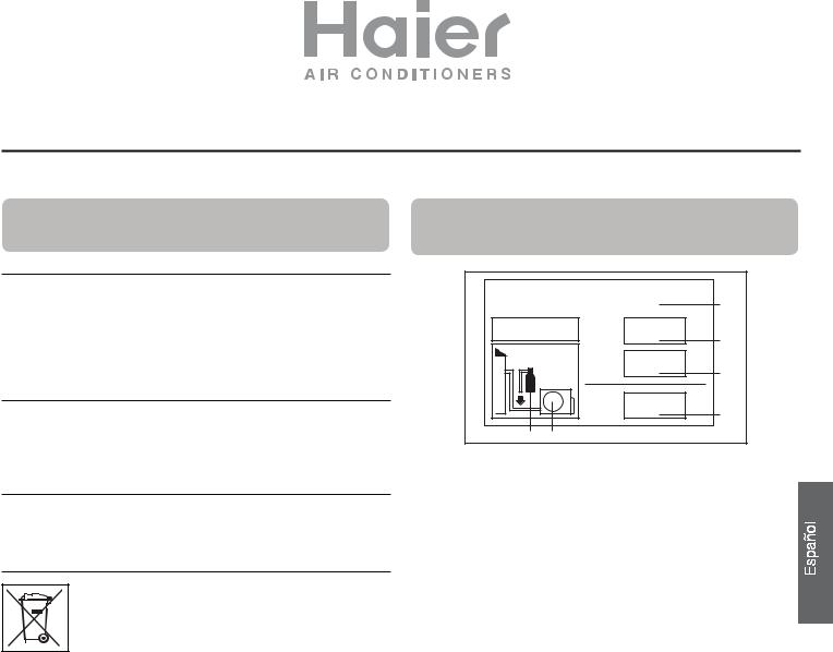
Dibujos de instalación de las unidades interior y exterior
Los modelos cumplen la norma R410A sobre refrigerantes libres de HFC.
Para obtener información sobre la instalación de las unidades interiores, consulte el manual de instalación proporcionado con las mismas.
(El diagrama muestra una unidad interior montada en pared.)
más de 15 cm
más de 10 cm
Organización de la dirección de los tubos
Izquierda Izquierda trasera Derecha
 trasera
Derecha
Inferior
más de 20 cm
Debe prestarse atención a la pendiente del manguito de drenaje
G
más de 10 cm
F
A
C
Componentes opcionales para
la instalación de los tubos
A Cinta no adhesiva
BCinta adhesiva
C Soporte (L.S) con tornillos
D |
Conexión de cable eléctrico para inte- |
rior y exterior |
EManguito de drenaje
F Material aislante de calor
G Cubierta de orificio de entubación
más de 20 cm 
Fijación de la unidad exterior
●Las marcas comprendidas entre A y G en la ilustración corresponden a los números de las piezas.
●La distancia entre la unidad interior y el suelo debe ser superior a 2 m.
más de 60 cm

 D
D
E
más de 25 cm
 SALIDA DE AIRE
  ENTRADA DE AIRE
●Fije la unidad a un bloque de cemento con pernos (10 mm) y tuercas firme y horizontalmente.
●Si instala la unidad sobre una pared, techo o tejado, instale un soporte con clavos o cables considerando la posibilidad de terremotos o viento fuerte.
●Si la vibración afectase a la casa, fije la unidad instalando una alfombra de absorción de vibraciones.
 TUBOS DE CONEXIÓN Y CABLEADO ELÉCTRICO
4 |
4 MANGUITO DE DRENAJE |
Compresor (dentro de la unidad)
●La imagen anterior de las unidades interior y exterior solamente sirve de referencia. Remítase al producto real adquirido.
15

Precauciones de seguridad
Lea detenidamente la siguiente información para poner en funcionamiento el aire acondicionado de forma correcta. A continuación se enumeran tres tipos de precauciones de seguridad y sugerencias.
 ADVERTENCIA Si realiza operaciones de forma incorrecta, pueden producirse graves consecuencias, como la muerte o graves lesiones.
 PRECAUCIÓN Si realiza operaciones de forma incorrecta, pueden producirse lesiones o daños en la máquina; en algunos casos pueden producirse graves consecuencias.
INSTRUCCIÓN: Esta información puede asegurar el correcto funcionamiento de la máquina. Símbolos utilizados en las ilustraciones
 : indica una acción que se debe evitar.
 : indica que es obligatorio seguir las instrucciones importantes.
 : indica un componente que se debe conectar a tierra.
 : atención a las descargas eléctricas (este símbolo se muestra en la etiqueta de la unidad principal.) Después de leer este manual, entréguesela a aquellas personas que utilicen a la unidad.
El usuario de esta unidad debe tener este manual a mano y ponerlo a disposición de quienes repararán o reubicarán la unidad. Asimismo, debe ponerlo a disposición de los nuevos usuarios cuando el producto cambio de manos.
Asegúrese de seguir estas importantes precauciones de seguridad.
 ADVERTENCIA
● Si se producen fenómenos anormales |
|
|
(por ejemplo, olor a quemado), corte la |
Desactivar |
|
fuente de alimentación inmediatamente, |
||
|
||
y póngase en contacto con el distribuidor |
|
para averiguar el método de manipulación.
En dicho caso, si sigue utilizando el aire acondicionado, éste resultará dañado, y pueden producirse descargas eléctricas o peligro de incendio.
● Tras un largo período de tiempo sin utilizar el aparato de aire acondicionado, debe comprobar la base para ver si se han producido daños.
Si la base dañada no se repara, es posible que la unidad se caiga y provoque accidentes.
●No desmonte la boca de salida de la unidad exterior.
La exposición del ventilador es muy peligrosa, ya que puede provocar lesiones en las personas.
●Cuando necesite mantenimiento y reparación, llame al distribuidor para gestionarlo.
Si el mantenimiento y la reparación se realizan de forma incorrecta podrían producirse fugas de agua, descargas eléctricas y peligro de incendio.
 ADVERTENCIA
● No se pueden colocar cosas o personas sobre la unidad exterior. La caída de cosas o personas puede provocar accidentes.
● No ponga en funcionamiento el aire acondicionado con las manos mojadas. De lo contrario, se producirán descargas eléctricas.
● Utilice sólo fusibles del tipo correcto.
No se puede utilizar ningún cable ni otro material que sustituya al fusible, de lo contrario, se producirán fallos o incendio.
●Utilice el tubo de descarga correctamente para asegurar la eficacia de la descarga. Si utiliza el tubo de forma incorrecta podrían producirse fugas de agua.
●Interruptor de circuito de fugas eléctricas instalado.
Provoca descargas eléctricas con facilidad sin el interruptor de circuito.
●El aire acondicionado no puede instalarse en lugares con gases inflamables, ya que podrían provocar peligro de incendio.
El distribuidor es el responsable de la instalación del aparato de aire acondicionado. Si la instalación se realiza de forma incorrecta podrían producirse fugas de agua, descargas eléctricas y peligro de incendio.
●Llame al distribuidor para tomar medidas que eviten fugas de refrigerante.
Si el aparato de aire acondicionado está instalado en una habitación pequeña, asegúrese de tomar las medidas necesarias para evitar asfixia, incluso en caso de fuga de refrigerante.
●Cuando el aire acondicionado se instala o se vuelve a instalar, el distribuidor en el responsable de dichas tareas.
Si la instalación se realiza de forma incorrecta podrían producirse fugas de agua, descargas eléctricas y peligro de incendio.
●Conecte el cable de conexión a tierra.
El cable de conexión a tierra no debe conectarse al tubo de gas, tubo de agua, barra pararrayos o línea
telefónica. Si la conexión a tierra se realiza de manera Puestatierra a incorrecta, podrían producirse descargas.
16
 Loading...