


Haier AB09SC2VHA, AB12SC2VHA, AB18SC2VHA, AD07SL2VHA, AD07SL2VHB Installation Guide
...Ductless Split Heat Pump
|
Outdoor Unit |
|
Installation Manual |
|
|
|
18K: 2U18MS2VHB |
|
|
24K: 3U24MS2VHB |
|
|
36K: 4U36MS2VHB |
|
|
Compact Cassette Type Indoor |
|
|
9K: AB09SC2VH* |
|
|
12K: AB12SC2VH* |
|
|
18K: AB18SC2VH* |
|
|
Wall Mount Type Indoor |
|
|
7K: AW07LC2VH* |
|
|
9K: AW09LC2VH* |
|
|
12K: AW12LC2VH* |
|
|
18K: AW18LC2VH* |
|
|
Slim Duct Type Indoor |
|
|
7K: AD07SL2VH* |
|
|
9K: AD09SL2VH* |
|
|
12K: AD12SL2VH* |
|
|
18K: AD18SL2VH* |
|
|
Table of Contents |
|
Outdoor Unit Installation.................................................................................................................. |
|
2-13 |
Introduction - Overview..................................................................................................................................... |
|
2-4 |
Step 1 - Preparation............................................................................................................................................... |
|
5 |
Step 2 - Installation of the Outdoor Unit.............................................................................................................. |
|
6 |
Step 3 - Refrigerant Line Connections.............................................................................................................. |
|
6-8 |
Step 4 - Leak Test and Evacuation.................................................................................................................... |
|
8-9 |
Step 5 - Electrical Connections.................................................................................................................... |
|
10-11 |
Step 6 - Charging................................................................................................................................................. |
|
12 |
Step 7 - System Test........................................................................................................................................... |
|
12 |
Step 8 - Explaining Operation to the End User................................................................................................... |
12 |
|
Seacoast Application........................................................................................................................................... |
|
13 |
Indoor Unit Installation - Cassette.................................................................................................. |
|
14-19 |
Introduction - Overview................................................................................................................................ |
|
14-15 |
Step 1 - Preparation............................................................................................................................................. |
|
16 |
Step 2 - Installation of the Cassette Unit..................................................................................................... |
|
17-18 |
Step 3 - Electrical Connections.......................................................................................................................... |
|
19 |
Step 4 - Louver Installation................................................................................................................................. |
|
19 |
Step 5 - Pull Vacuum on System.......................................................................................................................... |
|
19 |
Indoor Unit Installation - Wall Mount............................................................................................... |
|
20-24 |
Introduction - Overview...................................................................................................................................... |
|
20 |
Step 1 - Preparation............................................................................................................................................. |
|
21 |
Step 2 - Installation of the Wall Mount Unit.................................................................................................. |
|
22-23 |
Step 3 - Electrical Connections.......................................................................................................................... |
|
24 |
Step 4 - Pull Vacuum on System.......................................................................................................................... |
|
24 |
Indoor Unit Installation - Slim Duct................................................................................................. |
|
25-30 |
Introduction - Overview................................................................................................................................ |
|
25-26 |
Step 1 - Preparation............................................................................................................................................. |
|
27 |
Step 2 - Installation of the Slim Duct Unit.................................................................................................... |
|
28-29 |
Step 3 - Electrical Connections.......................................................................................................................... |
|
30 |
Step 4 - Pull Vacuum System............................................................................................................................... |
|
30 |
Remote Controller.......................................................................................................................... |
|
31-34 |
|
INSTALLATION |
PAGE 1 |
ENGLISH
ENGLISH
Outdoor Unit Installation
Introduction - Overview
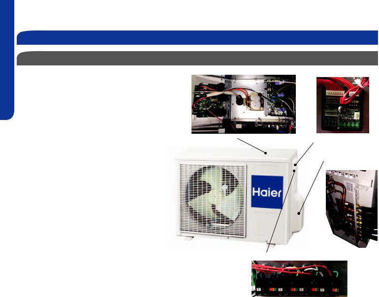
Outdoor Unit Product Information
The FlexFit Multi-zone Heat Pump systems feature DC |
|
|
invertertechnologytodeliverhighenergyefficiency. |
|
|
The inverter technology operates variable speed |
|
|
compressors and fan motors. The outdoor is equipped |
|
|
with electronic expansion valves , which control |
|
|
refrigerantflowindependentlytoeachindoorunitthat |
|
|
is installed. All of the outdoor units feature an internal |
|
|
oil separator to increase compressor live. These |
|
|
systems use R-410A refrigerant. |
Control Boards |
Self Diagnostic Board |
Some models feature self diagnostic boards that will |
|
|
checktheintegrityoffieldinstalledwiringpriortothe |
|
Flare Connections |
system start up. |
|
and Ports |
All outdoor units have built in diagnostic error |
|
|
detection circuits. If an error is detected, the |
|
|
system will take the necessary steps to either make |
|
|
adjustments or shut down to prevent damage from |
|
|
occuring. Some error codes will be displayed on the |
|
|
indoor unit display panel. |
|
|
These systems can be connected to up to 4 individual |
|
|
indoor units. It is not necessary to use all of the |
|
|
available ports. The available combinations of indoor |
|
|
and outdoor unit capacities are listed in this manual. |
|
Indoor Unit Power and Comm Wiring |
Available indoor units include high wall type, cassette |
|
|
|
|
|
type and Slim Duct/Concealed type. |
|
|
Refrigerantlineconnectionsareflareconnect. |
|
|
The outdoor unit provides power to indoor units via |
|
|
terminal connections on the outdoor unit. |
|
|
PAGE 2 |
INSTALLATION |

Introduction - Overview
Outdoor Unit Product Information
Temperature Control and the Inverter
The outdoor unit inverter will operate the compressor, outdoor fan motor and indoor fan motor at the proper speed to provide enough capacity to satisfy the heat load from all operating indoor units.
As the temperature in the zones gets closer to the setpoint requirement, the inverter will slow everything down. This is normal operation.
As temperature setpoint is reached, the inverter will run everything slowly to provide small amounts of capacity to keep the rooms comfortable. At times, the air coming out of the indoor units will be close to or at room temperature. This is normal.
This precise match of capacity and load is how ductless air conditionersacheivehighefficiencyratings.
Matching up the outdoor unit to indoor units
The approved combinations of indoor unit capacity and outdoor unit model are shown at the right. The capacity ratings can be matched to any of the high wall, cassette, or Slim Duct/Concealed models.
The systems are not rated for use of only 1 indoor unit. Do not vary from the available combinations in these tables.
When ports are not used, always connect the refrigerant lines to circuits located at the outdoor units lowest possible connection.Uselinereducingfittingstotransitionfromthe outdoor port size to the required port size of the indoor unit.
Operating Temperature Ranges
•Cool Mode: 14OF - 114OF
•Heat Mode: 5OF - 74OF
ENGLISH
INSTALLATION |
PAGE 3 |

|
|
Introduction - Overview |
|
|
||
ENGLISH |
|
ProductSpecifications |
|
|
||
|
|
|
|
|
|
|
Model Number |
Outdoor |
2U18MS2VHB |
|
3U24MS2VHB |
4U36MS2VHB |
|
|
|
|||||
|
|
|
|
|
|
|
|
|
Rated Capacity Btu/hr |
17,400 |
|
22,500 |
34,000 |
|
|
|
|
|
|
|
|
|
Capacity Range Btu/hr |
4,400-19,400 |
|
5,000-24,500 |
5,000-36,000 |
|
|
|
|
|
|
|
|
Cooling Non-ducted |
Rated Power Input W |
1,650 |
|
2,250 |
3,770 |
|
|
|
|
|
|
|
|
|
SEER |
16.0 |
|
18.0 |
18.0 |
|
|
|
|
|
|
|
|
|
EER |
10.5 |
|
10.0 |
9.0 |
|
|
|
|
|
|
|
|
|
Rated Capacity Btu/hr |
16,500 |
|
21,000 |
31,000 |
|
|
|
|
|
|
|
|
|
Capacity Range Btu/hr |
4,400-19,400 |
|
5,000-23,000 |
5,000-34,000 |
|
|
|
|
|
|
|
|
Cooling Ducted |
Rated Power Input W |
1,800 |
|
2,416 |
3,590 |
|
|
|
|
|
|
|
|
|
SEER |
15.5 |
|
16.0 |
16.0 |
|
|
|
|
|
|
|
|
|
EER |
8.5 |
|
8.5 |
8.5 |
|
|
|
|
|
|
|
|
|
Rated Heating Capacity 47°F Btu/hr |
19,100 |
|
23,000 |
34,500 |
|
|
|
|
|
|
|
|
|
Heating Capacity Range Btu/hr |
6,100-22,100 |
|
6,100-25,500 |
6,100-36,500 |
|
|
|
|
|
|
|
|
|
Rated Power Input W |
1,570 |
|
1,700 |
2,650 |
|
|
|
|
|
|
|
|
Heating Non-ducted |
HSPF |
9.0 |
|
10.0 |
10.0 |
|
|
Rated Heating Capacity 17°F Btu/hr |
13,000 |
|
15,000 |
22,000 |
|
|
|
|
|
|
|
|
|
Max. Heating Capacity 17°F Btu/hr |
14,000 |
|
18,000 |
26,000 |
|
|
|
|
|
|
|
|
|
Max. Heating Capacity 5°F Btu/hr |
12,000 |
|
16,000 |
24,000 |
|
|
|
|
|
|
|
|
|
Rated Heating Capacity 47°F Btu/hr |
18,000 |
|
22,000 |
33,000 |
|
|
|
|
|
|
|
|
|
Heating Capacity Range Btu/hr |
6,100-22,100 |
|
6,100-25,000 |
6,100-35,000 |
|
|
|
|
|
|
|
|
|
Rated Power Input W |
1,700 |
|
2,100 |
3,000 |
|
|
|
|
|
|
|
|
Heating Ducted |
HSPF |
8.2 |
|
8.5 |
9.0 |
|
|
|
|
|
|
|
|
|
Rated Heating Capacity 17°F Btu/hr |
10,000 |
|
14,000 |
21,000 |
|
|
|
|
|
|
|
|
|
Max. Heating Capacity 17°F Btu/hr |
12,000 |
|
17,000 |
25,000 |
|
|
|
|
|
|
|
|
|
Max. Heating Capacity 5°F Btu/hr |
10,000 |
|
15,000 |
23,000 |
|
|
|
|
|
|
|
|
Operating Range |
Cooling °F(°C) |
14~115(-10~46) |
|
14~115(-10~46) |
14~115(-10~46) |
|
|
|
|
|
|
|
|
Heating °F(°C) |
-4~75(-20~24) |
|
-4~75(-20~24) |
-4~75(-20~24) |
|
|
|
|
||||
|
Power Supply |
Voltage, Cycle, Phase V/Hz/- |
208-230/60/1 |
|
208-230/60/1 |
208-230/60/1 |
|
|
|
|
|
|
|
|
|
Compressor Type |
|
|
DC Interver Driven Rotary |
|
|
|
|
|
|
|
|
|
|
Maximum Fuse Size A |
25 |
|
25 |
30 |
|
|
|
|
|
|
|
|
|
Minimum Circuit Amp A |
15 |
|
18 |
23 |
|
|
|
|
|
|
|
|
|
Outdoor Fan Speed RPM |
300 ~ 900 |
|
300 ~ 900 |
300 ~ 900 |
|
|
|
|
|
|
|
|
Outdoor Unit |
Outdoor Noise Level dB |
53 |
|
54 |
56 |
|
|
|
|
|
|
|
|
|
Dimension: Height in (mm) |
27 1/16(688) |
|
28 3/4(730) |
33 1/16(840) |
|
|
|
|
|
|
|
|
|
Dimension: Width in (mm) |
31 7/8(810) |
|
33 7/8(860) |
37 5/16(948) |
|
|
|
|
|
|
|
|
|
Dimension: Depth in (mm) |
11 5/16(288) |
|
12 1/8(308) |
13 3/8(340) |
|
|
|
|
|
|
|
|
|
Weight (Ship/Net)- lbs (kg) |
102.5/95.9(46.5/43.5) |
|
123.4/116.8(56/53) |
191.8/167.5(87/76) |
|
|
|
|
|
|
|
|
Indoor Unit |
Max Indoor units |
2 |
|
3 |
4 |
|
|
|
|
|
|
|
|
|
Connections |
Flare |
|
Flare |
Flare |
|
|
|
|
|
|
|
|
|
Liquid O.D. in |
1/4 1/4 |
|
1/4 1/4 1/4 |
1/4 1/4 1/4 1/4 |
|
|
|
|
|
|
|
|
|
Suction O.D. in |
3/8 3/8 |
|
3/8 3/8 3/8 |
3/8 3/8 3/8 1/2 |
|
|
|
|
|
|
|
|
Refrigerate Line |
Factory Charge Oz |
49.5 |
|
74.0 |
113.0 |
|
|
|
|
|
|
|
|
Maximum Line Length Ft / m |
100/30 |
|
200/60 |
230/70 |
|
|
|
|
||||
|
|
|
|
|
|
|
|
|
Maximum Height Ft / m |
50/15 |
|
50/15 |
50/15 |
|
|
|
|
|
|
|
|
|
Maximum Line Length for each indi- |
82/25 |
|
82/25 |
82/25 |
|
|
vidual indoor unit Ft / m |
|
|||
|
|
|
|
|
|
|
|
|
|
|
|
|
|
PAGE 4 |
INSTALLATION |

Required Tools for Installation
•Drill
•Wire Snipper
•Hole Saw 2 3/4”
•Vacuum pump
•Soap-and-water solution or gas leakage detector
•Torque wrench
•17mm, 22mm, 26mm
•Tubing cutter
•Flaring tool
•Razor knife
•Measuring tape
•Level
•Micron gauge
•Nitrogen
•Mini-Split AD-87 Adapter (1/4” to 5/16”)
•A - Non-adhesive Tape
•B - Adhesive Tape
•C - Saddle (L.S.) with screws
•D - Electrical wiring
•E - Drain hose (Included)
•F - Insulation
•G - Piping hole cover (Included)
ore |
than4in. |
more |
|
m |
|
than |
|
4 |
|
in |
|
. |
|
Step 1 - Preparation
Procedure for Selecting the Location
•Choose a place solid enough to bear the weight and vibration of the unit and where the operation noise will not be amplified.
•Choose a location where the hot air discharged from the unit or the operation noise and will not cause a nuisance to the neighbors of the user.
•Theremustbesufficientspacefor carrying the unit into and out of the site.
•Theremustbesufficientspaceforair passage and no obstructions around the air inlet and air outlet.
•The site must be free from the possibility offlammablegasleakageinanearby place.
•Locate the unit to avoid noise and discharged hot air will not annoy the neighbors.
•Install units, power cords and inter-unit cables at least 10ft away from television and radio sets. This is to prevent interference to images and sounds. (Noise may be heard even if they are
Outdoor Unit Clearances
more than 10ft away depending on radio wave conditions.)
• Sincedrainflowsoutoftheoutdoorunit, do not place anything under the unit that must be kept away from moisture.
Note:
1)Cannot be installed hanging from ceiling or stacked.
2)If installing on a high place such as a roof, with a fence or guard rail around it.
3)If there is a potential for accumulated snow to block the air inlet or heat exchanger, install the unit on a higher base.
4)R-410A refrigerant is a safe, nontoxic and nonflammablerefrigerant.However,if there is a concern about a dangerous level of refrigerant concentration in the case of refrigerant leakage, add extra ventilation.
5)Avoid installing the outdoor unit where corrosive gases, such as sulfur oxides, ammonia, and sulfurous gas, are produced. If unavoidable, consult with an installation specialist about using a corrosion-proof or anti-rust additive to protect the unit coils.
ENGLISH
more |
|
tha |
|
n |
|
8 |
in. |
. in 24 than more
. 6in than more
.
more than 10 in
INSTALLATION |
PAGE 5 |
ENGLISH
Step 2 - Installation of the Outdoor Unit
Set the Outdoor Unit
Step 2.2
2.1 Step - 2.1
Set the unit on mount or pad. If located in snow area, use heat pump risers to elevate the outdoor unit.
Make sure the outdoor unit is installed level and is stable.
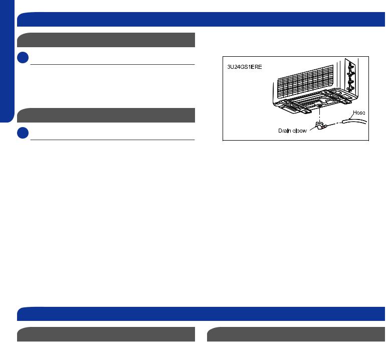
Attaching Drain Elbow to Outdoor Unit
2.2 Step - 2.2
If the unit is located in an area where freezing can occur, do notinstalltherubberdrainfittingontothebottomoftheunit. Iftheareastaysabovefreezing.Insertthedrainfittingper these instructions.
If attaching the supplied drain elbow to the outdoor unit, do so prior to attaching the refrigerant lines and wiring.
Extensionpipingtoattachtothisfittingisfieldsupplied.
Use drain plug for drainage.
Ifthedrainportiscoveredbyamountingbaseorfloor surface, place additional foot bases of at least 1 1/6 in. in height under the outdoor unit’s feet.
In cold areas, do not use a drain hose with the outdoor unit. (Otherwise, drain water may freeze, impairing heating performance.)
Step 3 - Refrigerant Line Connections
Piping Limits |
Pipe Size |
The maximum lift allowed between the outdoor unit and COMBINED indoor units is 50 feet total of all installed units. For example, 3 units with 15 elevation each is 45 feet.
The maximum allowable piping length for ALL INSTALLED indoor units is a total of:
18K Outdoor Models: 100 Feet
24K Outdoor Models: 200 Feet
36K Outdoor Models: 230 Feet
The maximum refrigerant piping length allowable to a Cassette unit is 82 feet.
Use the refrigerant line size that is indicated in the specification informationforeachindoorunit.Usestub adapters to adapt size to the outdoor unit if necessary.
PAGE 6 |
INSTALLATION |

Step 3 - Refrigerant Line Connections
Connection Priority
The line sets are connected to the indoor piping port connections labeled A through
D.Theconnectionsaremadewithaflare fitting.Flarenutfittingsareincludedwith the unit.
Note: Start the connections at the lowest port. Always size the lines to the requirement of the indoor unit. Use a line size adapteriftherequiredlinesizediffersfrom the port size on the outdoor unit.
If any ports are not used, they remain capped. Unused ports should be near the top of the outdoor unit connection manifold. Remember, always start from bottom to top.
ENGLISH
INSTALLATION |
PAGE 7 |

ENGLISH
Step 3 - Refrigerant Line Connections
Piping Connection |
Step 3.2 |
3.1 Step - 3.1
Refrigerant piping connections for the mini-split system are madeutilizingflareconnections.Followstandardpractices forcreatingpipeflares.Whencuttingandreamingthetubing, use caution to prevent dirt or debris from entering the tubing. Remember to place the nut on the pipe before creating the flare.
3.2 Step - 3.2
To join the lineset piping together, directly align the piping flaretothefittingontheotherpipe,thenslidethenutonto thefittingandtighten.Misalignmentmayresultinaleaking connection.
3.3 Step - 3.3
Twowrenchesarerequiredtojointheflareconnections,one standard wrench, and one torque wrench. See Table 1 for the specifictorqueperpipingdiameter.
Step 3.1
Step 3.3
Table 1
Half union |
Flare nut |
Spanner Torque wrench
Forced fastening without careful centering may damage the threads and cause a leakage of gas.
Pipe Diameter(ǿ) |
Fastening torque |
|
|
Liquid side6.35mm(1/4") |
18N.m/13.3Ft.lbs |
|
|
Liquid/Gas side9.52mm(3/8") |
42 N.m/30.1Ft.lbs |
|
|
Gas side 12.7mm(1/2") |
55N.m/40.6Ft.lbs |
|
|
Gas side 15.88mm(5/8") |
60 N.m/44.3Ft.lbs |
|
|
Step 4 - Leak Test and Evacuation
Leak Test
4.1 Step - 4.1
HazardofExplosion!Neveruseanopenflametodetect gas leaks. Explosive conditions may occur. Use a leak test solution or other approved methods for leak testing. Failure to follow recommended safe leak test procedures could result In death or serious injury or equipment or property damage.
Use only dry nitrogen with a pressure regulator for pressurizing unit. Do not use acetylene, oxygen or compressed air or mixtures containing them for pressure testing. Do not use mixtures of a hydrogen containing refrigerant and air above atmospheric pressure for pressure testingastheymaybecomeflammableandcouldresultin an explosion. Refrigerant, when used as a trace gas should only be mixed with dry nitrogen for pressurizing units. Failure to follow these recommendations could result in death or serious injury or equipment or property damage.
Using a tank of nitrogen with attached regulator, charge the system with 150 PSIG of dry nitrogen. Use adapter AD-
87(fieldsupplied)toconnecttothevalve.Checkforleaks attheflarefittingsusingsoapbubblesorotherdetection methods. If a leak is detected, repair and recheck. If no leaks are detected, proceed to evacuate the system.
Step 4.1
PAGE 8 |
INSTALLATION |
Step 4 - Leak Test and Evacuation
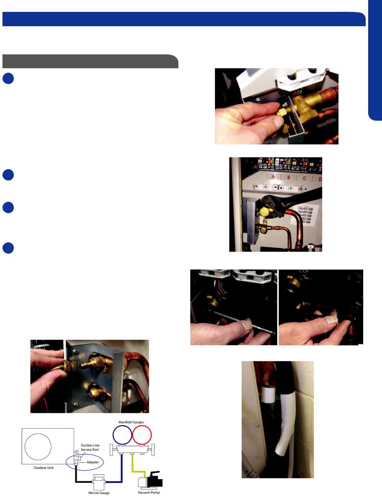
Note: This system has one set of service valves. When evacuating the system, the service valve ports will have access to all indoor units and refrigerant line sets. Evacuation at the service valve ports will evacuate the ENTIRE piping system including indoor units.
|
System Evacuation |
Step 4.3 |
||
4.2 Step - 4.2 |
|
|||
|
|
|
|
|
Attach a manifold gauge, micron gauge, and vacuum pump |
|
|||
tothesuctionlineportusingadapterAD-87(fieldsupplied). |
|
|||
(Illustration 5) |
|
|||
Evacuate the system to 350 microns. |
|
|||
Close the vacuum pump valve and check the micron |
|
|||
gauge. If the gauge rises above 500 microns in 60 seconds, |
|
|||
evacuation is incomplete or there is a leak in the system. If |
Step 4.4A |
|||
the gauge does not rise above 500 microns in 60 seconds, |
||||
|
||||
evacuation is complete. |
|
|||
4.3 Step - 4.3 |
|
|||
|
|
|
|
|
Remove the adapter and hose connection from the suction |
|
|||
line port, and replace the cap. |
|
|||
4.4 Step - 4.4A & 4.4B |
|
|||
|
|
|
|
|
Remove the caps from the liquid line and suction line valves |
|
|||
valve. Using the hex wrench, open each of the valves, then |
|
|||
replace and tighten the caps. |
|
|||
4.5 Step - 4.5 |
|
|||
|
|
|
|
|
Wrap the lineset, drain line, and wiring starting at the bottom |
Step 4.4B |
|||
of the bundle with an overlap type wrap, concluding at the |
|
|||
piping hole. Use a sealant to seal the piping hole opening to |
|
|||
prevent weather elements from entering the building. |
|
|||
Verify the condensate drain line has a constant pitch |
|
|||
downwardforproperwaterflow.Thereshouldbenokinksor |
|
|||
risesinthetubingwhichmaycauseatrappingeffectresulting |
|
|||
in the failure of the condensate to exit the piping. |
|
|||
|
Step 4.2 |
|
||
|
|
|
Step 4.5 |
|
Illustration 5
ENGLISH
INSTALLATION |
PAGE 9 |

ENGLISH
Step 5 - Electrical Connections
Wiring Unit |
Step 5.1 |
|
5.1 Step - 5.1
Remove the cover plate of the outdoor unit to expose the terminal block connections.
5.2 Step -5.2
Connect Line Voltage from Circuit Breaker/Disconnect to outdoor unit wire terminal
Always follow local and national codes when installing electrical wiring. The required fuse size can be found in the productspecificationsectionofthismanual.
Connect wiring from indoor units
Use14/4 AWG Stranded wire when connecting the outdoor unit to the indoor unit. Connect the wiring to the correct terminals based upon the piping connections. For example, Circuit A wiring goes to the piping feeding Circuit A. Do not cross the wiring and piping.
Step 5.2
Line Voltage
Terminals
Indoor Unit Terminals
5.3 Step - 5.3
Replace the cover plate.
PAGE 10 |
INSTALLATION |
|
|
|
Step 5 - Electrical Connections |
|
|
|
|
|
|
|
|
|
|
|
|
|
|
|
|||||
|
Wiring Error Check |
|
|
|
|
|
|
|
|
|
|
|
|
|
|
|
|||||||
This unit is capable of automatically checking for wiring errors |
|
|
|
|
|
|
|
|
|
|
|
|
|
|
|
||||||||
between the indoor and outdoor units. |
Illustration 6 |
|
|
|
|
||||||||||||||||||
|
|
|
|
|
|
|
|
|
|
|
|
|
|
|
|
|
|
|
|
|
|
|
|
To enter the wiring error check test, place all 4 DIP switches |
|
|
|
|
|
|
|
|
|
|
|
|
|
|
|
|
|
||||||
|
|
|
|
|
|
|
|
|
|
|
|
|
|
|
|
|
|||||||
|
|
|
|
|
|
|
|
|
|
|
|
|
|
|
|
|
|||||||
of the test board to the ON position. (Illustration 6) Remove |
|
|
|
|
|
|
|
|
|
|
|
|
|
|
|
|
|
||||||
and reapply power to the unit, the system will enter the |
|
|
|
|
|
|
|
|
|
|
|
|
|
|
|
|
|
||||||
operation of “Wiring Error Check”. |
|
|
|
|
|
|
|
|
|
|
|
|
|
|
|
|
|
||||||
|
|
|
|
|
|
|
|
|
|
|
|
|
|
|
|
|
|||||||
The numeric display will initialize and begin to alternate |
|
|
|
|
|
|
|
|
|
|
|
|
|
|
|
|
|
||||||
|
|
|
|
|
|
|
|
|
|
|
|
|
|
|
|
|
|||||||
|
|
|
|
|
|
|
|
|
|
|
|
|
|
|
|
|
|||||||
|
|
|
|
|
|
|
|
|
|
|
|
|
|
|
|
|
|||||||
|
|
|
|
|
|
|
|
|
|
|
|
|
|
|
|
|
|||||||
|
|
|
|
|
|
|
|
|
|
|
|
|
|
|
|||||||||
between the compressor working frequency (a number |
|
|
|
|
|
|
|
|
|
|
|
|
|
|
|
|
|
||||||
representing the Hz value) and “CH” (Checking). |
|
|
|
|
|
|
|
|
|
|
|
|
|
|
|
|
|
||||||
|
|
|
|
|
|
|
|
|
|
|
|
|
|
|
|
|
|||||||
As the check is being performed, all units that are properly |
|
|
|
|
|
|
|
|
|
|
|
|
|
|
|
|
|
||||||
connected will be indicated by the corresponding LED for |
|
|
|
|
|
|
|
|
|
|
|
|
|
|
|
|
|
||||||
that circuit being lit constantly. (LED 1 = piping circuit A, LED |
|
|
|
|
|
|
|
|
|
|
|
|
|
|
|
|
|
||||||
2 = piping circuit B, ...) |
|
|
|
|
|
|
|
|
|
|
|
|
|
|
|
|
|
||||||
|
|
|
|
|
|
|
|
|
|
|
|
|
|
|
|
|
|||||||
After the check has completed, if all wiring is correct, |
|
|
|
|
|
|
|
|
|
|
|
|
|
|
|
||||||||
the numeric display will indicate “0” and the single LEDs |
|
|
|
|
|
|
|
|
|
|
|
|
|
|
|
||||||||
representing the individual circuits for the connected indoor |
|
|
|
|
|
|
|
|
|
|
|
|
|
|
|
||||||||
units will be lit constantly. |
|
|
|
|
|
|
|
|
|
|
|
|
|
|
|
||||||||
Ifthereareanymiswiredunits,thenumericdisplaywillflash |
|
|
|
|
|
|
|
|
|
|
|
|
|
|
|
||||||||
“EC” (error connection), and th corresponding LED for the |
|
|
|
|
|
|
|
|
|
|
|
|
|
|
|
||||||||
miswiredcircuitwillflash.Checkandcorrectthewiringas |
|
|
|
|
|
|
|
|
|
|
|
|
|
|
|
||||||||
needed. |
|
|
|
|
|
|
|
|
|
|
|
|
|
|
|
||||||||
Refer to the chart shown below. (Table 2) |
|
|
|
|
|
|
|
|
|
|
|
|
|
|
|
||||||||
When the test is complete, remove power to the system and |
|
|
|
|
|
|
|
|
|
|
|
|
|
|
|
||||||||
return the 4 DIP switches to the OFF position. Reapply power |
|
|
|
|
|
|
|
|
|
|
|
|
|
|
|
||||||||
to the the system. The test is complete. |
|
|
|
|
|
|
|
|
|
|
|
|
|
|
|
||||||||
If the self-check is not possible, check the indoor unit wiring |
|
|
|
|
|
|
|
|
|
|
|
|
|
|
|
||||||||
and piping in the usual manner. |
|
|
|
|
|
|
|
|
|
|
|
|
|
|
|
||||||||
|
|
|
|
|
Table 2 |
|
|
|
|
|
|
|
|
|
|
|
|
|
|
|
|||
|
|
|
|
|
|
|
|
|
|
|
|
|
|
|
|
|
|
|
|
|
|
|
|
|
|
|
|
|
|
|
|
|
|
|
|
|
|
|
|
|
|
|
|
|
|
|
|
|
|
|
|
|
|
|
|
|
|
|
|
|
|
|
|
|
|
|
|
|
|
|
|
|
|
|
|
|
|
|
|
|
|
|
|
|
|
|
|
|
|
|
|
|
|
|
|
|
|
|
|
|
|
|
|
|
|
|
|
|
|
|
|
|
|
|
|
|
|
|
|
|
|
|
|
|
|
|
|
|
|
|
|
|
|
|
|
|
|
|
|
|
|
|
|
|
|
|
|
|
|
|
|
|
|
|
|
|
|
|
|
|
|
|
|
|
|
|
|
|
|
|
|
|
|
|
|
|
|
|
|
|
|
|
|
|
|
|
|
|
|
|
|
ENGLISH
INSTALLATION |
PAGE 11 |
 Loading...