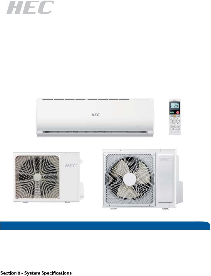
Haier 1U09BU1ERH, 1U12BU1ERH, 1U15RU1ERE, 1U18RU1ERE, 1U24SU1ERE Installation Guide
...
Ductless Split Air Conditioner
Installation Manual |
Indoor |
Outdoor |
|
AS09TB1HRH |
1U09BU1ERH |
||
|
|||
|
AS12TB1HRH |
1U12BU1ERH |
|
|
AS15TD1HRE |
1U15RU1ERE |
|
|
AS18TD1HRE |
1U18RU1ERE |
|
Note: |
AS24TE1HRE |
1U24SU1ERE |
|
|
|
3OHDVHPDNHVXUHWKHSRZHUVXSSO\FRUUHFWO\DWƪUVW N N YROWDJHZKLOH N N N YROWDJH
|
Table of Contents |
|
Step 1 - Preparation ...................................................................................................................... |
2 |
|
Step 2 - Installation of the Indoor Unit........................................................................................... |
3 |
|
Step 3 |
- Installation of the Outdoor Unit........................................................................................ |
4 |
Step 4 |
- Interconnecting the Indoor and Outdoor Units ................................................................. |
5 |
Step 5 |
- Leak Test and Evacuation.................................................................................................. |
6 |
Step 6 |
- Charging........................................................................................................................... |
7 |
Section 7 - Explaining Operation to the End User........................................................................... |
8 |
|
|
.................................................................................................. |
8 |
Section 9 - Seacoast Application ................................................................................................... |
8 |
|
0010590560

ENGLISH
Required Tools for Installation |
Procedure for Selecting the Location |
Ţ Drill |
|
Ţ :LUHSnipper |
|
Ţ +ROH6aZ Ş |
|
Ţ VDFXXPSXPS |
|
Ţ Soap-and-wDWHUVROXWLRQRUJDVOHDkDJH |
|
detector |
|
Ţ TRUTXHZUHQFK |
|
Ţ PP PP PP |
Ior |
Ţ TXELQJFXtter |
FDUU\LQJWKHXQLWLQtRDQGRXWRIWKHVLWH |
Ţ FODULQJtool |
Ior DLU |
Ţ RazRUNQLIH |
SDVVDJHDQGQRREVWUXFWLRQVDrRXQGWKH |
Ţ 0HDVXULQJWDSH |
DLULQOHWDQGDLURXWOHW |
Ţ Level |
Ţ TKHVLWHPXVWEHIUHHIrRPWKHSRVVLELOLt\ |
Ţ MicrRQJDXJH |
|
Ţ NitrRJHQ |
place. |
Ţ Mini-SSOLW$' $GDSWHU ŞtR Ş |
Ţ LRFDWHWKHXQLWtRavRLGQRLVHDQG |
Ţ $ 1RQ DGKHVLYHTape |
GLVFKDUJHGKoWDLUZLOOQoWDQQo\WKH |
Ţ % $GKHVLYHTape |
QHLJKERrV. |
Ţ & 6DGGOH /.S ZLWKVFUewV |
Ţ ,QVWDOOXQLWV SoZHUcRUGVDQGLQWHr XQLW |
Ţ ' (OHFWULFDOZLULQJ |
FDEOHVDWOHDVW IWawa\IrRPWHOeYLVLRQ |
Ţ ( 'rDLQKRVH ,QFOXGHG |
DQGrDGLRVHWV TKLVLVtRSUeYHQW |
Ţ ) ,QVXODWLRQ |
LQWHUIHUHQFHtRLPDJHVDQGVRXQGV |
Ţ * PLSLQJKROHcoYHU ,QFOXGHG |
1RLVHPa\EHKHDUGeYHQLIWKe\DUHPRUH |
WKHUHLVDcRQFHUQDERXWDGDQJHrRXVOeYHO RIUHIULJHrDQWconcentrDWLRQLQWKHFDVHRI UHIULJHrDQWOHDkDJH DGGextrDYHQWLODWLRQ
$vRLGLQVWDOOLQJWKHRXWGRRUXQLWZKHUH corrRVLYHJDVHV VXFKDVVXOIXUoxideV DP PRQLD DQGVXOIXrRXVJDV DUHSrRGXFHG ,I unavRLGDEOH cRQVXOWZLWKDQLQVWDOODWLRQ VSHFLDOLVWabout XVLQJa corrRVLRQ SrRRIRU DQWL UXVWDGGLWLYHtRSroWHFWWKHXQLWcoilV
Clearances of Indoor and Outdoor Units
TKLVSLFtXUHLVIor UHIHUHQFHRQOy.YRXUSrRGXFW may to WKHXVHUDFcRUGLQJto WKLVPDQXDO
TKe modelV adopt HFC Iree reIriJerant R 1 $
mRUHWKDQ LQ |
$WWHQWLRQPXVWEHSDLGWR |
WKHSLWFKRIGUDLQKRVH |
mRUHWKDQ LQ
$rUDQJemenWRI pipinJ directionV
|
Rear leIt |
LeIt |
Rear |
|
riJKW |
|
RiJKt |
|
Below |
mRUHWKDQ LQ
 TKe marNV Irom $ to G in tKe
  Jure are tKe
QDPHRIWKHSDUWV
 TKe diVtance between tKe indoor unit and tKe
  oor VKould be more tKan IHHW
mRUHWKDQ LQ
PAGE 2
G
Floor xinJ dimenVionV RIWKe outdoor unit
8nit: LQFK
mRUHWKDQ LQ
F |
|
|
Z |
|
$ |
|
|
|
|
|
|
|
|
|
1 |
|
|
|
|
C |
'LPHQVLRQV LQFKHV |
|
||
Model |
1 |
|
[ |
|
|
|
|
||
8 %8 (5+ |
Ş |
|
Ş |
|
mRUHWKDQ LQ |
|
|
|
|
8 58 (5( |
Ş |
Ş |
Ş |
Ş |
8 68 (5( |
Ş |
Ş |
Ş |
Ş |
 D
D
(
mRUHWKDQ LQ
FixinJRIRutdoor unit
 Fix tKe unitWRFoncrete or block witK boltV1 mm VHFXUHO\
 WKen
WKen  ttinJ tKe unitWo ZDll VXrIace, rooI or roRItop,
  [WKHXQLWVHFXUHO\LQFRQVLGHUDWLRQ RI eartKquake and VtronJ wind.
 ,I vibration may DIIect tKe KouVe,
  x tKe unit b\DWtacKinJD vibration-proRI mat.
INSTALLATION

Step 2 - Installation of the Indoor Unit
Attaching the Mounting Plate to the Wall
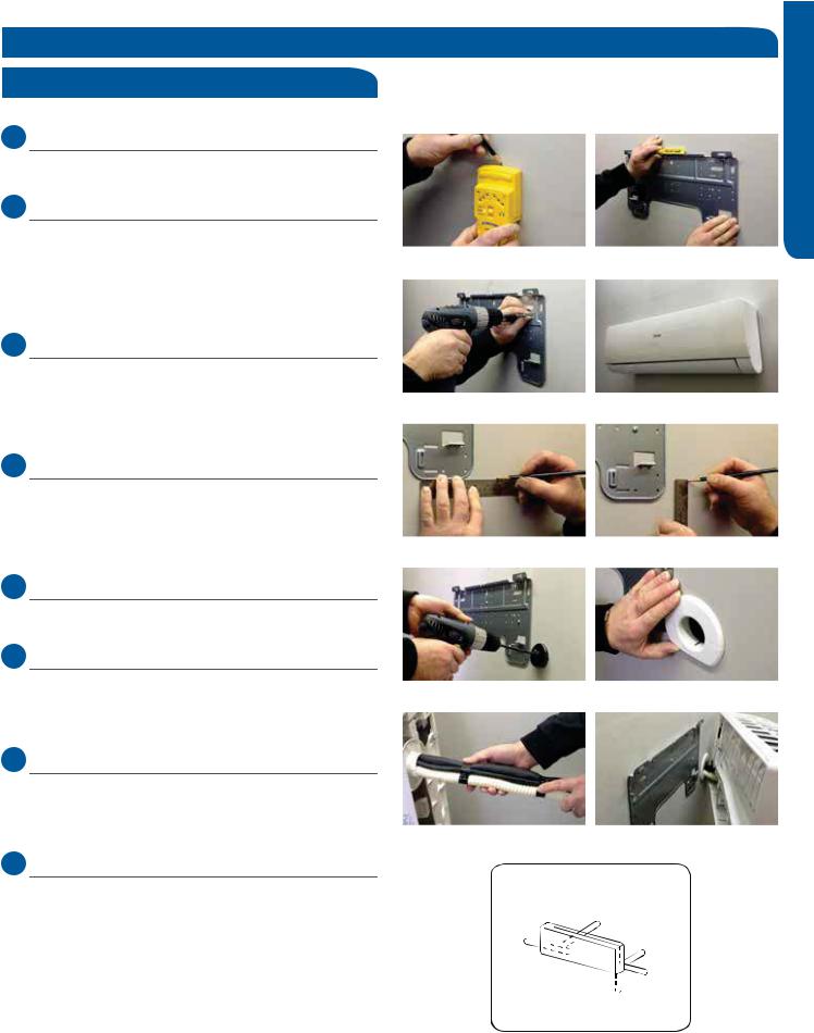
2.1 Step 2.1
Using a stud sensor, locate and mark the stud positions in the wall where the indoor unit is to be mounted.
2.2 Step 2.2
Place the mounting plate on the wall in the desired location taking into account the minimum clearances necessary for proper operation.
Using a level, verify the mounting plate is horizontal and mark the screw locations.
2.3 Step 2.3
Screw the mounting plate to the wall.
The piping for the indoor unit may be routed to the unit from one of several directions. Left, Left Rear, Right, Right Rear, or Below (Illustration 1).
2.4 Step 2.4
Knockouts are provided on the case for Left, Right, and Right Below.
Drilling the hole through the wall for left rear or right rear installation
2.5 Step 2.5A & 2.5B
Measure and mark the location where the piping hole is to be drilled.
2.6 Step 2.6
Drill the piping hole using a hole saw of the correct diameter. Angle the drill with a downward pitch to the outside wall so that the outside hole will be ¼” lower than the inside hole, giving the hole the proper angle for condensate drainage.
2.7 Step 2.7
,QVWDOOWKHSLSLQJKROHFRYHUƫDQJHDWWKHKROHRSHQLQJRQWKH inside wall.
127( 7KHFRYHUƫDQJHPD\UHTXLUHPRGLƪFDWLRQWRƪW properly behind the wall unit housing.
2.8 Step 2.8A & 2.8B
Bundle the refrigerant piping, drain piping and wiring with tape and pass the bundle through the piping hole.
127( :KHQEXQGOLQJWKHSRZHUFDEOH OHDYHVXƬFLHQWOHQJWK available in the indoor unit to make the connections to the terminal block.
Step 2.1 |
Step 2.2 |
Step 2.3 |
Step 2.4 |
Step 2.5A |
Step 2.5B |
Step 2.6 |
Step 2.7 |
Step 2.8A |
Step 2.8B |
Piping Exit Options |
|
Rear left |
|
Left |
Rear |
|
right |
|
Right |
Below |
|
Illustration 1 |
|
ENGLISH
INSTALLATION |
PAGE 3 |
 Loading...