


 SERVICE MANUAL
LED TV
MODEL No. 32E2000

 WARNING
This service information is designed for experienced repair technicians only and is not designed for use by the general public.
It does not contain warnings or cautions to advise non-technical individuals of potential dangers in attempting to service a product. Products powered by electricity should be serviced or repaired only by experienced professional technicians. Any attempt to service or repair the product or products dealt with in this service information by anyone else could result in serious injury or death.
Downloaded from www.Manualslib.com manuals search engine

Service Manual
Model No.: 32E2000
Table of Contents
1. General Information . . . . . . . . . . . . . . . . . . . . . . . . . . . . . . . . . .3
1-1. General Guidelines . . . . . . . . . . . . . . . . . . . . . . . . . . .3 1-2. Important Notice . . . . . . . . . . . . . . . . . . . . . . . . . . . . .3 1-3. How to Read this Service Manual . . . . . . . . . . . . . . . .6
2. Specifications . . . . . . . . . . . . . . . . . . . . . . . . . . . . . . . . . . . . . .7 3. Location of Controls and Components . . . . . . . . . . . . . . . . . .8
3-1 Component Location . . . . . . . . . . . . . . . . . . . . . . . . . . .8 3-2 Main Board . . . . . . . . . . . . . . . . . . . . . . . . . . . . . . . . . .8 3-3 LED Panel . . . . . . . . . . . . . . . . . . . . . . . . . . . . . . . . . .11
4. Disassembly Procedures . . . . . . . . . . . . . . . . . . . . . . . . . . . .12 5. Accessories . . . . . . . . . . . . . . . . . . . . . . . . . . . . . . . . . . . . . . .17 6. Installation Instructions . . . . . . . . . . . . . . . . . . . . . . . . . . . . .18
6-1 Power Connection . . . . . . . . . . . . . . . . . . . . . . . . . . .18 6-2 External Equipment Connections . . . . . . . . . . . . . . . .19
7. Operation Instructions . . . . . . . . . . . . . . . . . . . . . . . . . . . . . .25
7-1 Side Control . . . . . . . . . . . . . . . . . . . . . . . . . . . . . . . .25 7-2 Rear Terminals . . . . . . . . . . . . . . . . . . . . . . . . . . . . . .26 7-3 Using Remote Control . . . . . . . . . . . . . . . . . . . . . . . .27
8. Electrical Parts . . . . . . . . . . . . . . . . . . . . . . . . . . . . . . . . . . . . .28
8-1 System Block Diagram . . . . . . . . . . . . . . . . . . . . . . . .28 8-2 Circuit Diagram . . . . . . . . . . . . . . . . . . . . . . . . . . . . . .29 8-3 Wiring Connection Diagram . . . . . . . . . . . . . . . . . . . .35
- 1 -
Downloaded from www.Manualslib.com manuals search engine

Service Manual
Model No.:32E2000
9. Measurements and Adjustment . . . . . . . . . . . . . . . . . . . . . . .36
9-1 Operation Guide . . . . . . . . . . . . . . . . . . . . . . . . . . . . .36
9-2 Factory Mode . . . . . . . . . . . . . . . . . . . . . . . . . . . . . . .43
9-3 Software Update . . . . . . . . . . . . . . . . . . . . . . . . . . . . .44
9-4 Hotel Mode . . . . . . . . . . . . . . . . . . . . . . . . . . . . . . . . .44
10. Troubleshooting . . . . . . . . . . . . . . . . . . . . . . . . . . . . . . . . . .45
10-1 Simple Check . . . . . . . . . . . . . . . . . . . . . . . . . . . . . . |
46 |
|
10-2 |
Power supply . . . . . . . . . . . . . . . . . . . . . . . . |
47 |
10-3 |
Display . . . . . . . . . . . . . . . . . . . . . . . . |
49 |
10-4 |
Audio . . . . . . . . . . . . . . . . . . . . . . . . . . . . . |
50 |
10-5 |
Function . . . . . . . . . . . . . . . . . . . . . . . . . . . . . |
51 |
- 2 -
Downloaded from www.Manualslib.com manuals search engine

Service Manual
Model No.: 32E2000
1. General Information
1-1. General Guidelines
When servicing, observe the original lead dress. If a short circuit is found, replace all parts which have been overheated or damaged by the short circuit.
After servicing, see to it that all the protective devices such as insulation barriers, insulation papers shields are properly installed.
After servicing, make the following leakage current checks to prevent the customer from being exposed to shock hazards.
1)Leakage Current Cold Check
2)Leakage Current Hot Check
3)Prevention of Electrostatic Discharge (ESD) to Electrostatically Sensitive
1-2. Important Notice
1-2-1. Follow the regulations and warnings
Most important thing is to list up the potential hazard or risk for the service personnel to open the units and disassemble the units. For example, we need to describe properly how to avoid the possibility to get electrical shock from the live power supply or charged electrical parts (even the power is off).
This symbol indicates that high voltage is present inside.It is dangerous to make any king of contact with any inside part of this product.
This symbol indicates that there are important operating and maintenance instructions in the literature accompanying the appliance.
1-2-2. Be careful to the electrical shock
To prevent damage which might result in electric shock or fire, do not expose this TV set to rain or excessive moisture. This TV must not be exposed to dripping or splashing water, and objects filled with water, such as vases, must be placed on top or above the TV.
1-2-3. Electrostatic discharge (ESD)
Some semiconductor (solid state) devices can be damaged easily by static electricity. Such components commonly are called Electrostatically Sensitive (ES) Devices. The following techniques should be used to help reduce the incidence of component damage caused by electrostatic discharge (ESD).
1-2-4. About lead free solder (PbF)
This product is manufactured using lead-free solder as a part of a movement within the consumer products industry at large to be environmentally responsible. Lead-free solder must be used in the servicing and repairing of this product.
1-2-5. Use the specified parts
Special parts which have purposes of fire retardant (resistors), high-quality sound (capacitors), low noise (resistors), etc. are used.
When replacing any of components, be sure to use only manufacture's specified parts shown in the parts list.
- 3 -
Downloaded from www.Manualslib.com manuals search engine

Service Manual
Model No.: 32E2000
Safety Component
 Components identified by
  mark have special characteristics important for safety.
1-2-6 Safety Check after Repair
Confirm that the screws, parts and wiring which were removed in order to service are put in the original positions, or whether there are the positions which are deteriorated around the serviced places serviced or not. Check the insulation between the antenna terminal or external metal and the AC cord plug blades. And be sure the safety of that.
General Servicing Precautions
1.Always unplug the receiver AC power cord from the AC power source before;
a.Removing or reinstalling any component, circuit board module or any other receiver assembly.
b.Disconnecting or reconnecting any receiver electrical plug or other electrical connection.
c.Connecting a test substitute in parallel with an electrolytic capacitor in the receiver.
CAUTION: A wrong part substitution or incorrect polarity installation of electrolytic capacitors may result in an explosion hazard.
2.Test high voltage only by measuring it with an appropriate high voltage meter or other voltage measuring device (DVM, FETVOM, etc) equipped with a suitable high voltage probe.
3.Do not test high voltage by "drawing an arc".
4.Do not spray chemicals on or near this receiver or any of its assemblies.
5.Unless specified otherwise in this service manual, clean electrical contacts only by applying the following mixture to the contacts with a pipe cleaner, cotton-tipped stick or comparable non-abrasive applicator; 10% (by volume) Acetone and 90% (by volume) isopropyl alcohol (90%-99% strength).
CAUTION: This is a flammable mixture. Unless other specified in this service manual, lubrication of contacts is not required. Capacitors may result in an explosion hazard.
6.Do not defeat any plug/socket B+ voltage interlocks with which receivers covered by this service manual might be equipped.
7.Do not apply AC power to this instrument and/or any of its electrical assemblies unless all solid-state device heat sinks are correctly installed.
8.Always connect the test receiver ground lead to the receiver chassis ground before connecting the test receiver positive lead. Always remove the test receiver ground lead last. Capacitors may result in an explosion hazard.
9.Use with this receiver only the test fixtures specified in this service manual.
10.Remove the antenna terminal on TV and turn on the TV.
11.Insulation resistance between the cord plug terminals and the external exposure metal should be more than Mohm by using the 500V insulation resistance meter.
12.If the insulation resistance is less than M ohm, the inspection repair should be required. If you have not the 500V insulation resistance meter, use a Tester. External exposure metal: Antenna terminal Headphone jack.
- 4 -
Downloaded from www.Manualslib.com manuals search engine

Service Manual
Model No.: 32E2000
Electrostatically Sensitive (ES) Devices
Some semiconductor (solid-state) devices can be damaged easily by static electricity. Such components commonly are called Electrostatically Sensitive (ES) Devices. Examples of typical ES devices are integrated circuits and some field-effect transistors and semiconductor "chip" components. The following techniques should be used to help reduce the incidence of component damage caused by static by static electricity.
1.Before handling any semiconductor component or semiconductor equipped assembly, immediately drain off any electrostatic charge on your body by touching a known earth ground. Alternatively, obtain and wear a commercially available discharging wrist strap device, which should be removed to prevent potential shock reasons prior to applying power to the unit under test.
2.After removing an electrical assembly equipped with ES devices, place the assembly on a conductive surface such as aluminum foil, to prevent electrostatic charge buildup or exposure of the assembly.
3.Use only a grounded-tip soldering iron to solder or unsolder ES devices.
4.Use only an anti-static type solder removal device. Some solder removal devices not classified as “anti-static” can generate electrical charges sufficient to damage ES devices.
5.Do not use freon-propelled chemicals. These can generate electrical charges sufficient to damage ES devices.
6.Do not remove a replacement ES device from its protective package until immediately before you are ready to install it.
(Most replacement ES devices are packaged with leads electrically shorted together by conductive foam, aluminum foil or comparable conductive material).
7.Immediately before removing the protective material from the leads of a replacement ES device, touch the protective material to the chassis or circuit assembly into which the device will be installed.
CAUTION: Be sure no power is applied to the chassis or circuit, and observe all other safety precautions.
8. Minimize bodily motions when handling unpackaged replacement ES devices.
(Otherwise harmless motion such as the brushing together of your clothes fabric or the lifting of your foot from a carpeted floor can generate static electricity sufficient to damage an ES device.)
1-2-7. Ordering Spare Parts
Please include the following informations when you order parts. (Particularly the Version letter)
1.Model number, Serial number and Software Version
The model number and Serial number can be found on the back of each product and the Software Version can be found at the Spare Parts List.
2.Spare Part No. and Description
You can find them in the Spare Parts List.
- 5 -
Downloaded from www.Manualslib.com manuals search engine
Service Manual
Model No.: 32E2000
1-2-8. Photo used in this manual
The illustration and photos used in this Manual may not base on the final design of products, which may differ from your products in some way.
1-3. How to Read this Service Manual
Icons:
Icons are used to attract the attention of the reader to specific information. The meaning of each icon is described in the table below:
Note:
A “note” provides information that is not indispensable, but may nevertheless be valuable to the reader, such as tips and tricks.
Caution:
A “caution” is used when there is danger that the reader, through incorrect manipulation, may damage equipment, data loss, get an unexpected result or has to restart (part of) a procedure.
Warning:
A “warning” is used when there is danger of personal injury.
Reference:
A “reference” guides the reader to other places in this binder or in this manual, where he/ she will find additional information on a specific topic.
- 6 -
Downloaded from www.Manualslib.com manuals search engine

Service Manual
Model No.: 32E2000
2. Specifications |
|
|
|
|
|
|
Model |
32E2000 |
|
|
|
|
Screen Size |
31.5 inch |
|
|
|
|
Aspect Ratio |
16:9 |
|
|
|
|
Resolution |
1366 x 768 |
|
|
|
|
Response Time (ms) |
8 |
|
|
|
|
Angle of View |
H:178° V: 178° |
|
|
|
|
Color Display |
16.7 M |
|
|
|
|
OSD Language |
English/French/Spanish |
|
|
|
|
Video/Audio System |
ATSC/NTSC/M/MTS |
|
|
|
|
Dimensions with Stand (W x H x D) |
22.82X18.39X7.12 Ib |
|
|
|
|
Dimensions w/o Stand (W x H x D) |
22.82X16.83X2.72 Ib |
|
|
|
|
Weight with Stand |
9.79 Ib |
|
|
|
|
Weight without Stand |
9.71 Ib |
|
|
|
|
Wall Mount Pattern (H x V) |
200 x 100 mm |
|
|
|
|
Wall Mount Screw Type |
M6 x 8mm |
|
|
|
|
Power Consumption |
50 W |
|
|
|
|
Standby |
<1W |
|
|
|
|
Mains Power |
120V~60HZ |
|
|
|
|
Audio Power |
8W + 8W |
|
|
|
- 7 -
Downloaded from www.Manualslib.com manuals search engine

Service Manual
Model No.: 32E2000
3. Location of Controls and Components
3-1 Component Location
1
6
7
3 2
4
5
No. |
Component |
|
|
1 |
LED Panel |
|
|
2 |
System Main Board |
|
|
3 |
Power cord |
|
|
4 |
Left and Right Speakers |
|
|
5 |
Panel T-Con Board |
|
|
6 |
Keypad Board |
|
|
7 |
IR LED Board |
|
|
3-2 Main Board
- 8 -
Downloaded from www.Manualslib.com manuals search engine

Service Manual
Model No.: 32E2000
3-2-1 Function Description
Process signal which incept from exterior equipment then translate into signal that panel can display.
3-2-2 Connector Definition
- 9 -
Downloaded from www.Manualslib.com manuals search engine
Service Manual
Model No.: 32E2000
- 10 -
Downloaded from www.Manualslib.com manuals search engine

Service Manual
Model No.:32E2000
- 11 -
Downloaded from www.Manualslib.com manuals search engine

Service Manual
Model No.: 32E2000
4.Disassembly Procedures
1.Remove the screws securing the back cover. Torque: 3.8 ± 0.53 kgf-cm.
- 12 -
Downloaded from www.Manualslib.com manuals search engine
Service Manual
Model No.: 32E2000
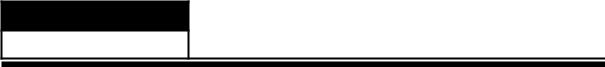
2. Detach the back cover from left to right and remove it from the unit.
3. Remove all tapes on the cables.
- 13 -
Downloaded from www.Manualslib.com manuals search engine

Service Manual
Model No.:32E2000
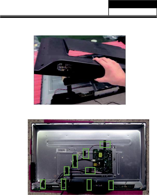
4. Disconnect the cables and remove them from the unit.
5. Remove the screws securing the main board, Speaker side I/O cover and bottom I/O cover, then remove them from the unit. Torque: 3.8±0.3 kgf-cm.
- 14 -
Downloaded from www.Manualslib.com manuals search engine
Service Manual
Model No.: 32E2000
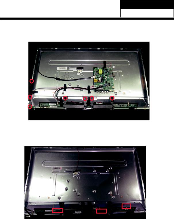
6.Delete the speaker stents and press keypad remote control board screw Torque: 3.8±0.3 kgf-cm.
7. Disconnect your screen line and conductive cloth.
- 15 -
Downloaded from www.Manualslib.com manuals search engine
 Loading...