


R410A |
UNITARY SMART |
|
|
DUCT TYPE 100Pa
INDOOR UNIT
EN OPERATION MANUAL INSTALLATION MANUAL
IT MANUALE DI ISTRUZIONI MANUALE DI INSTALLAZIONE
FR MANUEL D’INSTRUCTIONS MANUEL D’INSTALLATION
DE BEDIENUNGSANLEITUNGINSTALLATIONSANLEITUNG
ES MANUAL DE INSTRUCCIONES MANUAL DE INSTALACIÓN
ON-OFF INVERTER
AD282AHEAA AD362AHERA
AD362AHEAA AD482AHERA
AD482AHEAA AD602AHERA
AD602AHEAA
Please read this manual carefully before using this air conditioner |
|
Please keep this manual safely for future use |
No. 0150503056 C |

Haier Industrial Park, No.1 Haier Road, Qingdao, P.R.China
IT CONFORMITÀ ALLE DIRETTIVE EUROPEE PER I MODELLI:
AD282AHEAA AD362AHEAA AD482AHEAA AD602AHEAA AD362AHERA AD482AHERA AD602AHERA
CE
Tutti i prodotti sono conformi alle seguenti normative europee:
-Direttiva 73/23/EEC Basso Voltaggio
-Direttiva 2006/95/EC Basso Voltaggio
-Direttiva 89/336/EEC Compatibilità elettromagnetica
ROHS
Il prodotto è conforme alla normativa 2002/95/EEC sulla restrizione d’uso di sostanze inquinanti negli apparecchi elettrici ed elettronici.
WEEE
Informativa al consumatore come previsto dalla normativa europea 2002/96/CE riguardante i rifiuti di apparecchiature elettriche ed elettroniche.
SPECIFICHE DI SMALTIMENTO:
Il climatizzatore è contrassegnato con questo simbolo, ciò significa che i prodotti elettrici ed elettronici non possono essere smaltiti insieme ai rifiuti domestici non
differenziati. Non cercare di demolire il sistema da soli: la demolizioni dei sistemi di condizionamento, nonché il recupero del refrigerante, dell’olio e di qualsiasi altra
 parte devono essere eseguiti da un installatore qualificato in conformità alla legislazione locale e nazionale vigente in materia.I climatizzatori devo essere trattati presso una struttura spe-
cializzata nel riutilizzo, riciclaggio e recupero dei materiali. Il corretto smaltimento del prodotto eviterà le possibili conseguenze negative all’ambiente e alla salute dell’uomo. Per maggiori informazioni contattare l’installatore o le autorità locali. Le batterie devono essere tolte dal telecomando e smaltite separatamente conformemente alla legislazione locale e nazionale vigente in materia.
EN EUROPEAN REGULATIONS CONFORMITY FOR THE MODELS:
AD282AHEAA AD362AHEAA AD482AHEAA AD602AHEAA AD362AHERA AD482AHERA AD602AHERA
CE
All the products are in conformity with the following European provision:
-Low Voltage Directive 73/23/EEC
-Low Voltage Directive 2006/95/EC
-Electromagnetic CompatibilitY 89/336/EEC
ROHS
The products are fulfilled with the requirements in the directive 2002/95/EEC of the European parliament and of the council on the Restriction of the use of Certain Hazardous Substances in Electrical and Electronic Equipment (EU RoHS Directive).
WEEE
In accordance with the directive 2002/96/CE of the European parliament, herewith we inform the consumer about the disposal requirements of the electrical and electronic products.
DISPOSAL REQUIREMENTS:
Your air conditioning product is marked with this symbol. This means that electrical and electronic products shall not be mixed with unsorted household waste.
Do not try to dismantle the system yourself: the dismantling of the air conditioning system, treatment of the refrigerant, of oil and of other part must be done
by a qualified installer in accordance with relevant local and national legislation.
Air conditioners must be treated at a specialized treatment facility for re-use, recycling and recovery. By ensuring this product is disposed of correctly, you will help to prevent potential negative consequences for the environment and human health. Please contact the installer or local authority for more information. Battery must be removed from the remote controller and disposed of separately in accordance with relevant local and national legislation.
FR CONFORMITÉ AUX DIRECTIVES EUROPÉENNES POUR LES MODÈLES:
AD282AHEAA AD362AHEAA AD482AHEAA AD602AHEAA AD362AHERA AD482AHERA AD602AHERA
CE
Tous les produits sont conformes aux directives européennes suivantes:
-Directive 73/23/CEE Basse tension
-Directive 2006/95/CE Basse tension
-Directive 89/336/CEE Compatibilité électromagnétique
ROHS
L'appareil est conforme à la directive 2002/95/CEE relative à la limitation de l'utilisation de certains substances dangereuses dans les équipements électriques et électroniques.
DEEE (WEEE)
Information au consommateur comme le prévoit la directive européenne 2002/96/CE relative aux déchets d'équipements électriques et électroniques.
SPECIFICATIONS POUR L'ELIMINATION:
Ce pictogramme, apposé sur le climatiseur, signifie que les équipements électriques et électroniques ne peuvent pas être éliminés avec les déchets ménagers
non triés. Ne pas essayer de démanteler l'équipement soi-même: le démantèlement des systèmes de climatisation, ainsi que la récupération du frigorigène, de
 l'huile et de toute autre partie doivent être effectués par un installateur qualifié conformément à la législation locale et nationale en vigueur en la matière. Les climatiseurs doivent être
traités dans un centre spécialisé dans la réutilisation, le recyclage et la valorisation des matériaux. L'élimination correcte de ces appareils permet d'éviter les effets nocifs sur l'environnement et la santé humaine. Pour plus de renseignements contacter l'installateur ou les autorités locales. Les piles doivent être retirées de la télécommande et éliminées séparément, conformément à la législation locale et nationale en vigueur en la matière.
Haier Industrial Park, No.1 Haier Road, Qingdao, P.R.China
DE ÜBEREINSTIMMUNG MIT DEN EUROPÄISCHEN RICHTLINIEN FÜR DIE MODELLE:
AD282AHEAA AD362AHEAA AD482AHEAA AD602AHEAA AD362AHERA AD482AHERA AD602AHERA
CE
Alle Produkte erfüllen die folgenden europäischen Richtlinien:
-Niederspannungsrichtlinie 73/23/EWG
-Niederspannungsrichtlinie 2006/95/EG
-EMV-Richtlinie 89/336/EWG
ROHS
Das Produkt erfüllt die Richtlinie 2002/95/EWG zur Beschränkung der Verwendung bestimmter gefährlicher Stoffe in Elektround Elektronikgeräten.
WEEE
Verbraucherinformation laut europäischer Richtlinie 2002/96/EG zu Elektround Elektronik-Altgeräten.
HINWEISE ZUR ENTSORGUNG:
Das Klimagerät ist mit diesem Symbol gekennzeichnet, das darauf hinweist, dass Elektround Elektronikgeräte getrennt vom Hausmüll entsorgt werden müs-
sen. Verschrotten Sie die Anlage nicht selbst: die Verschrottung von Klimaanlagen, sowie die Rückgewinnung des Kältemittels, des Öls und aller sonstigen Tei-
 le müssen durch einen qualifizierten Installateur in Übereinstimmung mit den einschlägigen geltenden örtlichen und nationalen Vorschriften erfolgen. Die Klimageräte müssen bei
einem Unternehmen entsorgt werden, das auf die Verwertung, das Recycling und die Rückgewinnung der Materialien spezialisiert ist. Die richtige Entsorgung des Produkts hilft negative Auswirkungen auf Umwelt und Gesundheit zu vermeiden. Für weitere Informationen wenden Sie sich bitte an den Installateur oder die örtlichen Behörden. Die Batterien müssen aus der Fernbedienung entfernt und in Übereinstimmung mit den einschlägigen geltenden örtlichen und nationalen Vorschriften getrennt entsorgt werden.
ES CONFORMIDAD EUROPEA DE LAS REGULACIONES PARA LOS MODELOS:
AD282AHEAA AD362AHEAA AD482AHEAA AD602AHEAA AD362AHERA AD482AHERA AD602AHERA
CE
Todos los productos están en conformidad con las siguientes Normativas Europeas:
-Bajo Voltaje directiva 73/23/EEC
-Bajo Voltaje directiva 2006/95/EC
-Compatibilidad electromagnética 89/336/EEC
ROHS
Los productos cumplen los requisitos de la directiva 2002/95/EEC del parlamento Europeo y el consejo regulador Del uso de materiales peligrosos en equipamientos eléctricos Y electrónicos. (EU RoHS Directiva).
WEEE
De acuerdo con la directiva 2002/96/CE del parlamento Europeo, Informamos al consumidor acerca del reciclage de los productos Electrónicos y eléctricos.
REQUISITOS PARA LA ELIMINACIÓN:
Su acondicionador de aire está marcado con este símbolo. Esto significa que los productos eléctricos y electrónicos no deben mezclarse con el resto de resi-
duos domésticos no clasificados.
No intente desmontar el sistema usted mismo: El desmantelamiento del acondicionador de aire, así como el tratamiento del refrigerante, aceite y otros componentes, debe ser efectuado por un instalador compe-
tente de acuerdo con las normas locales y nacionales aplicables. Los acondicionadores de aire deben ser tratados en instalaciones especializadas para su reutilización, reciclaje y recuperación. Al asegurarse de desechar este producto de la forma correcta, està contribuyendo a evitar posibles consecuencias negativas para el entorno y para la salud de las personas. Contacte, por favor, con el instalador o con las autoridades locales para obtener más información. Las pilas del control remoto deben extraerse y eliminarse por separado y de acuerdo con la normativa local y nacional aplicable.

Haier Industrial Park, No.1 Haier Road, Qingdao, P.R.China
Contains fluorinated greenhouse gases |
|
covered by the Kyoto Protocol |
A |
R410A |
1= |
kg |
|
|
|
|
B |
2 |
|
2= |
kg |
|
1 |
|
C |
|
|
|
|
|
|
1+2= |
kg |
|
|
|
D |
F |
E |
|
|
IT
prodotto contiene gas fluorurati ad effetto serra inclusi nel Protocollo
. Non liberare tali gas nell’atmosfera.
refrigerante: R410A GWP*: 1975
= potenziale di riscaldamento globale
con inchiostro indelebile,
la carica di refrigerante di fabbrica del prodotto la quantità di refrigerante aggiuntiva nel campo e la carica di refrigerante totale
di carica del refrigerante fornita con il prodotto
L’etichetta compilata deve essere collocata in prossimità della portata di carica del prodotto (ad esempio, nell’interno del coperchio della valvola d’intercettazione).
Acontiene gas fluorurati ad effetto serra inclusi nel protocollo di Kyoto
Bcarica di refrigerante di fabbrica del prodotto: vedi targhetta con il nome dell’unità
Cquantità di refrigerante aggiuntiva nel campo
Dcarica di refrigerante totale
Eunità esterna
Fcilindro del refrigerante e collettore di carica
EN
|
contains fluorinated greenhouse gases covered by the Kyoto |
The filled out label must be adhered in the proximity of the product charging |
|
|
. Do not vent into the atmosphere. |
port (e.g. onto the inside of the stop valve cover). |
|
|
type: R410A |
A |
contains fluorinated greenhouse gases covered by the Kyoto Protocol |
|
value: 1975 |
B |
factory refrigerant charge of the product: see unit name plate |
|
= global warming potential |
C |
additional refrigerant amount charged in the field |
|
|
D |
total refrigerant charge |
|
fill in with indelible ink, |
E |
outdoor unit |
|
the factory refrigerant charge of the product |
F |
refrigerant cylinder and manifold for charging |
• 2 |
the additional refrigerant amount charged in the field and |
|
|
• 1+2 |
the total refrigerant charge |
|
|
on the refrigerant charge label supplied with the product.
FR
Ce produit contient des gaz à effet de serre fluorés encadrés par le protocole de Kyoto. Ne pas laisser les gaz s’échapper dans l’atmosphère.
Type de réfrigérant: R410A Valeur GWP*: 1975
*GWP = potentiel de réchauffement global
Prière de compléter à l’encre indélébile,
•1 la charge de réfrigérant d’usine du produit
•2 la quantité de réfrigérant supplémentaire chargée sur place et
•1+2 la charge de réfrigérant totale
sur l’étiquette de charge de réfrigérant fournie avec le produit.
L’étiquette complétée doit être apposée à proximité de l’orifice de recharge du produit (par ex. à l’intérieur du couvercle de la vanne d’arrêt).
Acontient des gaz à effet de serre fluorés encadrés par le protocole de Kyoto
Bcharge de réfrigérant d’usine du produit: voir plaquette signalétique de l’unité
Cquantité de réfrigérant supplémentaire chargée sur place
Dcharge de réfrigérant totale
Eunité extérieure
Fcylindre de réfrigérant et collecteur de recharge

Haier Industrial Park, No.1 Haier Road, Qingdao, P.R.China
Contains fluorinated greenhouse gases |
|
covered by the Kyoto Protocol |
A |
R410A |
1= |
kg |
|
|
|
|
B |
2 |
|
2= |
kg |
|
1 |
|
C |
|
|
|
|
|
|
1+2= |
kg |
|
|
|
D |
F |
E |
|
|
DE
Dieses Produkt enthält fluorierte Treibhausgase, die durch das Kyoto-Proto- koll abgedeckt werden. Lassen Sie Gase nicht in die Atmosphäre ab.
Kältemitteltyp: R410A
GWP* Wert: 1975
*GWP = Treibhauspotential
Bitte füllen Sie am Kältemittelbefülletikett, das im Lieferumfang des Gerätes enthalten ist, mit abriebfester Tinte wie folgt aus:
•1 die werkseitige Kältemittelbefüllung des Produktes
•2 die am Montageort befüllte zusätzliche Kältemittelmenge und
•1+2 die gesamte Kältemittelbefüllung
Das ausgefüllte Etikett muss in der Nähe der Kältemittel-Einfüllöffnung angehängt werden (z. B. auf der Innenseite der Absperrventilabdeckung).
AEnthält fluorierte Treibhausgase, die durch das Kyoto-ProtoKoll abgedeckt werden
Bwerkseitige Kältemittelbefüllung des Produktes: siehe Typenschild der Einheit
Czusätzliche am Montageort befüllen Kältemittelmenge
Dgesamte Kältemittelbefüllung
EAußeneinheit
FKältemittelzylinder und Sammelleitung für die Befüllung
ES
Este producto contiene los gases fluorados de efecto invernadora regulados por el Protocolo de Kioto. No vierta gases a la atmósfera.
Tipo de refrigerante: R410A Valor GWP*: 1975
*GWP = Potencial de calentamiento global
Rellene con tinta indeleble,
•1 la carga de refrigerante de fábrica del producto
•2 la cantidad adicional de refrigerante cargado en campo y
•1+2 la carga total de refrigerante
En la etiqueta de carga de refrigerante suministrada con el producto.
La etiqueta rellenada debe pegarse cerca de la conexión de carga del producto (p.ej. en el interior de la cubierta de la válvula de tope).
AContiene los gases fluorados de efecto invernadora regulados por el Protocolo de Kioto
BCarga de refrigerante de fábrica del producto: véase placa de especificaciones técnicas de la unidad
CCantidad adicional de refrigerante cargado en campo
DCarga total de refrigerante
EUnidad exterior
FCilindro del refrigerante y dosificador de carga

DUCT TYPE AIR CONDITIONER
Operation manual
Installation manual
On-Off Inverter
AD282AHEAA AD362AHERA
AD362AHEAA AD482AHERA
AD482AHEAA AD602AHERA
AD602AHEAA
 Please read this operation manual before using the air conditioner.
  Please keep this manual carefully and safely.

Contents
Cautions |
3 |
Safety Precautions |
4 |
Parts and Functions |
6 |
Operation |
9 |
Heating Mode |
12 |
Care and Maintenance |
13 |
Troubleshooting |
14 |
Precaution for Installation |
18 |
Is The Unit Installed Correctly |
19 |
Installation Procedure |
20 |
2

Cautions
Disposal of the old air conditioner
Before disposing an old air conditioner that goes out of use, please make sure it's inoperative and safe. Unplug the air conditioner in order to avoid the risk of child entrapment.
It must be noticed that air conditioner system contains refrigerants, which require specialized waste disposal. The valuable materials contained in a air conditioner can be recycled. Contact your local waste disposal center for proper disposal of an old air conditioner and contact your local authority or your dealer if you have any question. Please ensure that the pipework of your air conditioner does not get damaged prior to being picked up by the relevant waste disposal center, and contribute to environmental awareness by insisting on an appropriate, anti-pollution method of disposal.
Disposal of the packaging of your new air conditioner
All the packaging materials employed in the package of your new air conditioner may be disposed without any danger to the environment.
The cardboard box may be broken or cut into smaller pieces and given to a waste paper disposal service. The wrapping bag made of polyethylene and the polyethylene foam pads contain no fluorochloric hydrocarbon.
All these valuable materials may be taken to a waste collecting center and used again after adequate recycling.
Consult your local authorities for the name and address of the waste materials collecting centers and waste paper disposal services nearest to your house.
Safety Instructions and Warnings
Before starting the air conditioner, read the information given in the User's Guide carefully. The User's Guide contains very important observations relating to the assembly, operation and maintenance of the air conditioner.
The manufacturer does not accept responsibility for any damages that may arise due to non-observation of the following instruction.
 Damaged air conditioners are not to be put into operation. In case of doubt, consult your supplier.
 Use of the air conditioner is to be carried out in strict compliance with the relative instructions set forth in the User's Guide.
 Installation shall be done by professional people, don't install unit by yourself.
 For the purpose of safety, the air conditioner must be properly grounded in accordance with specifications.
 Always remember to unplug the air conditioner before opening inlet grill. Never unplug your air conditioner by pulling on the power cord. Always grip plug firmly and pull straight out from the outlet.
 All electrical repairs must be carried out by qualified electricians. Inadequate repairs may result in a major source of danger for the user of the air conditoiner.
 Do not damage any parts of the air conditioner that carry refrigerant by piercing or perforating the air conditioner's tubes with sharp or pointed items, crushing or twisting any tubes, or scraping the coatings off the surfaces. If the refrigerant spurts out and gets into eyes, it may result in serious eye injuries.
 Do not obstruct or cover the ventilation grille of the air conditioner. Do not put fingers or any other things into the inlet/outlet and swing louver.
 Do not allow children to play with the air conditioner. In no case should children be allowed to sit on the outdoor unit.
3

Safety Precautions
 Before starting to use the system, read carefully this "SAFETY PRECAUTIONS" to ensure a proper operation of the system.
 Safety precautions described here are classified to "
  WARNING" and "
  CAUTION". Precautions which are shown in the column of "
  WANING" means that an improper handing could lead to a grave result like a death, serious injury, etc. However, even if precautions are shown in the column of "
  CAUTION", a very serious problem could occur depending on situation. Make sure to observe these safety precautions faithfully because they are very important information to ensure the safety.
 Symbols which appear frequently in the text have following meanings.
Strictly prohibited. |
|
Observe instructions faithfully. |
|
Provide a positive grounding. |
|
|
|
|
|
 When you have read through the manual, keep it always at hand for read consultation. If the operator is replaced, make sure to hand over this manual to the new operator.
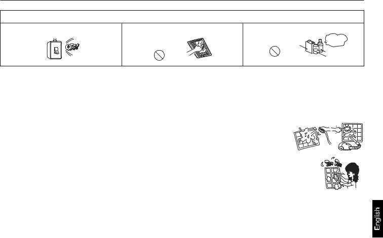
CAUTIONS FOR INSTALLATION
 WARNING
The system should be applied to places as office, restaurant, residence and the like.
Application to inferior environment such as an engineering shop, could cause equipment malfunction and serious injury or death.
The system should be installed by your dealer or a professional installer.
Installation by yourself is not encouraged because it could cause such problems as water leakage, electrical shock or fire accident by some improper handing.
When you need some optional devices such as a humidifier, electric heater, etc., be sure to use the products which are recommended by us. These devices should be attached by a professional installer.
Installation by yourself is not encouraged because it could cause such problems as water leakage, electrical shock or fire accident by some improper handing.
 CAUTION
Do not install nearby the place where may have leakage of flammable gas.
Depending on the place of installation, a circuit breaker may be necessary.
ON
OFF
Drain pipe should be arranged to provide a positive draining.
If the gas leakes and gathers around, it may cause |
Unless the circuit breaker is installed, it could cause |
If the pipe is arranged improperly, furniture or the |
the fire. |
elecrical shocks. |
likes may be damaged by leaked water. |
|
|
|
Where strong winds may prevail, the system |
Install on the place where can endure the weight |
Make sure the system is grounded. |
should be fixed securely to prevent a collapse. |
of air conditioner. |
|
Bodily injury could result by a collapse. |
Bodily injury could result by a careless installation. |
Grounding cable should never be connected to |
|
|
a gas pipe, city water pipe, lightning conductor |
|
|
rod or grounding cable of telephone. If the |
|
|
grounding cable is not set properly, it could cause |
|
|
electric shocks. |
CAUTIONS FOR TRANSFER OR REPAIR
 WARNING
Modification of the system is strictly prohibited. When the system needs a repair, consult your dealer.
Improper practice of repair could cause water leakage, electric shock or fire.
When the air conditioner is relocated, contact your dealer or a professional installer.
Improper practice of installation could cause water leakage, electric shock or fire.
4

Safety Precautions
CAUTIONS FOR OPERATION
 WARNING
You should refrain from exposing your body directly Do not poke the air inlet or outlet with a bar, etc. to cool wind for a long time. 
It could affect your physical condition or cause |
Since the internal fan is operating with a high |
some health problems. |
speed, it could cause an injury. |
When any abnormal condition (scorching smell or others) is found, stop the operation immediately and turn off the power switch. Then consult your dealer.
If you continue the operation without removing the cause, it could result in a trouble, electric shock or fire.
 CAUTION
The system should never be used for any other |
Do not handle switches with a wet hand. |
Combustion apparatus should not be placed |
purposes than intended such as for preservation |
|
allowing a direct exposure to wind of air conditioner. |
of food, flora and fauna, precision devices or work |
|
|
of art. |
|
|
It could cause deterioration of food or other |
It could cause electric shocks. |
Incomplete combustion could occur on the |
problems. |
|
apparatus. |
Do not wash the air conditioner with water. |
Do not install the system where the air outlet |
Make sure to use a fuse of proper electric rating. |
|
reaches directly the flora and fauna. |
|
It could cause electric shocks. |
It will not be good for their health. |
Use of steel or copper wire in place of a fuse is |
|
|
strictly prohibited because it could result in a trouble |
|
|
or fire accident. |
Neither stand on the air conditioner nor place something on it. 
There are risks of falling or injury by collapsed object.
It is strictly prohibited to place a container of combustible gas or liquid near the air conditioner or to spray it directly with the gas or liquid.
It could cause a fire accident.
Do not operate the system while the air outlet grill is removed.
There is a risk of injury.
Do not use the power switch to turn on or off the system.
ON
Do not touch the air outlet section while the swing louver is operating.
Do not use such equipment as a water heater, etc. around the indoor unit or the wire controller.
OFF
It could cause a fire or water leakage. |
There is a risk of injury. |
If the system is operated at the vicinity of such equipment which generates steam, condensed water may drip during cooling operation or it could cause a fault current or short-circuit.
When operating the system simultaneously with a combustion apparatus, indoor air must be ventilated frequently.
Check occasionally the support structure of the unit for any damage after a use of long period of time. 
When cleaning the system, stop the operation and turn off the power switch.
Insufficient ventilation could cause an oxygen |
If the structure is not repaired immediately, the |
Cleaning should never be done while the internal |
deficiency accident. |
unit could topple down to cause a personal injury. |
fans are running with high speed. |
Do not put water containers on the unit such as a flower vase, etc.
If the water enters into the unit and damages the electric insulation material, it may cause electric shock.
5

Safety Precautions
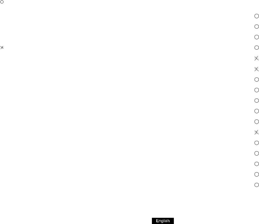
The machine is adaptive in following situation
1. Applicable ambient temperature range:
|
|
|
|
ON-OFF |
Inverter |
|
|
Indoor temperature |
max. |
DB/WB |
32/23 C |
32/23 C |
|
Cooling |
min. |
DB/WB |
18/14 C |
18/14 C |
||
|
||||||
Outdoor temperature |
max. |
DB/WB |
43/26 C |
43/26 C |
||
|
||||||
|
|
min. |
DB/WB |
10/6 C |
-5 C |
|
Heating |
Indoor temperature |
max. |
DB/WB |
27 C |
27 C |
|
min. |
DB/WB |
15 C |
15 C |
|||
|
|
|||||
|
Outdoor temperature |
max. |
DB/WB |
24/18 C |
24/18 C |
|
|
|
min. |
DB/WB |
-7 C |
-7 C |
2.If the supply cord is damaged, it must be replaced by the manufacturer or its service agent or a similar qualified person.
3.If the fuse on PC board is broken, please change it with the type of T 3.15A /250VAC.
4.The wiring method should be in line with the local wiring standard.
5.The power cable and connecting cable are self-provided. The connecting cable should be H05RN-F 4G 0.75mm2.
All the cables shall have got the European authentication certificate. During installation, when the connecting cables break off, it must be assured that the grouding wire is the last one to be broken off.
6.The breaker of the air conditioner should be all-pole switch, and the distance between its two contacts should be no less than 3mm.
7.The indoor unit installation height is at least 2.5m.
8.In order to obtain the Unit's best performances, the fan speed is recommended according to the following conditions.
outdoor ambient temp. |
operation mode |
recommended fan speed |
> 40 C |
cooling |
low |
< 20 C |
cooling |
high |
< -5 C |
heating |
low |
> 18 C |
heating |
high |
Parts and Functions
Indoor Unit
Air outlet
Duct
Duct
Drain pipe
Air inlet
6

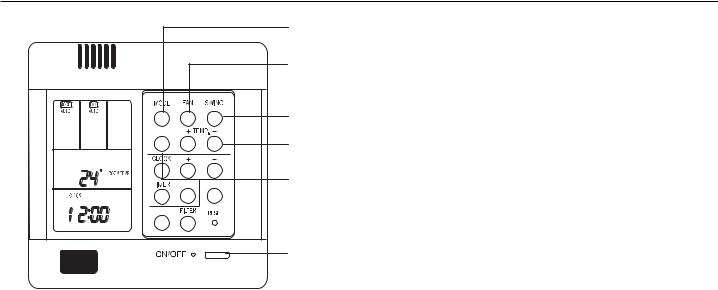
Parts and Functions
1 |
7 |
2
8
3
|
|
9 |
|
HEALTH |
|
|
|
10 |
C |
|
|
F |
SET |
RECOVERY |
|
CHECK |
|
|
|
11 |
4 |
|
5 |
12 |
|
|
6 |
13 |
1.CLOCK button
Used to adjust time.
2.TIMER button
Used to set timer mode.
3.CHECK button
Auto-diagnostic button.
4.+ and - button
Stands for time plus/minus, used to adjust time.
5.FILTER button
Filter-cleaned button.
6.POWER ON/OFF button
Used for unit to start and stop.
7.MODE button
Used to select indoor operation mode.
8.FAN button
Used to select indoor air flow.
9.SWING button
Used for setting indoor swing mode.
10.HEALTH button
Used for setting indoor health function.
11.TEMP + and - button
Used for changing set temperature.
12.RECOVERY button
used to switch over air-exchanging mode.
13.RESET button
Reset correct mode button.
Note:
The above information is the explanation of the displayed information. Therefore it varieswith those displayed in actual operation.
Cautions:
 On cooling only unit, heating mode is not available.
 The functions 5,9,10 are not available for these units.
7

Parts and Functions
HEALTH


 C
C
F |
SET RECOVERY |
CHECK
[MODE]
[AUTO]:Auto operation mode. [FAN ONLY]:Air-throwing mode. [COOL]:Cooling operation mode. [DRY]:Dehumidification mode. [HEAT]:Heating operation mode.
[TES]:In heating mode, auxiliary electric heater is running. Only when the unit with auxiliary electric heater is in auxiliary electric heating mode, it will display.
[FAN]
[AUTO]:Auto fan running. [HIGH]:High fan speed. [MED]:Medium fan speed. [LOW]:Low fan speed.
[FIX]:Fixed fan speed, it will display only when fixed fan speed is requested to main indoor unit.
[CENTRAL]:Central control mode.
[OPERATION]:Running mode.
[STAND BY]: Waiting mode. [PRE-HEAT]: Pre-heating mode. [DEFROST]: Defrosting mode. [FILTER]: Request of filter to be cleaned. [HEALTH]:Health function.
[CEN.ADD]:Central control address, the address number will display on "88".
[SYS.ADD.]:System address, the address number will display on "88".
[CHECK]:Auto-diagnostic, trouble shooting. [DEMAND]:Compulsory operation function, when it works, [CENTRAL] will flash.
[SWING][MANUAL]:Swing mode.
[ROOM TEMP.]:Indoor ambient temperature. [SET TEMP.]:Set admired temperature.
[TIMER]
[ON]:Timer function is on. [OFF] :Timer function is off.
[ON][OFF] :Timer function is ON-OFF. [ON][OFF][DAILY]:Timer ON-OFF will switch over in turn daily.
[CLOCK]:Clock display, the displaying time is the current time of the clock.
[UP],[DOWN]:Indicator of filter elevating.
[VENTILATION]
[AUTO]:Auto ventilation mode. [NORMAL]:Normal ventilation mode.
[RECOVERY]:Fully heat exchanging ventilation mode.
8

Operation
Fan Only
2 |
3 |
HEALTH |


 C
C 


SET RECOVERY
CHECK
1,4
(1)Start up operation:
Press the ON/OFF button. The system will start up and the display will be on LCD.
(2)Select operation mode :
Press the MODE button. Each press, operation mode in the [MODE] display section changes as follows:
[FAN ONLY]  [COOL]
  [DRY]
[DRY]  [HEAT]
  [AUTO]
  [FAN ONLY].
Select [FAN ONLY].
(3)Select fan speed:
Press the FAN button. Each press, fan speed in the [FAN] display section changes as follows:
[HIGH]  [MED]
[MED]  [LOW]
[LOW]  [HIGH]. Select proper fan speed.
(4)Power off:
Press the ON/OFF button. Indoor unit will be powered off, and there are only the time and the ambient temperature in the screen.
VENTILATION mode
(only for the unit with fresh air function or heat recovery function)
Press the RECOVERY button, then the unit will switch over the ventilation mode:
[ ]  [VENTILATION][AUTO]
  [VENTILATION][RECOVERY]
  [VENTILATION][NORMAL]
  [ ] Please select appropriate ventilation mode.
9
Operation
Auto, Cool, Heat and Dry
|
|
2 |
|
|
4 |
|
|
5 |
HEALTH |
|
3 |
|
|
|
C |
|
6 |
SET |
RECOVERY |
|
CHECK |
|
|
|
|
1,7 |
(1) Start up operation:
Press the ON/OFF button. The system will start up and the display will be on LCD.
(2) Select operation mode:
Press the MODE button. Each press, operation mode in the [MODE] display section changes as follows:
[FAN ONLY]  [COOL]
  [DRY]
[DRY]  [HEAT]
  [AUTO]
 [FAN ONLY].
Select operation mode ([COOL],[DRY],[HEAT],or [AUTO]).
(3) Set temperature:
Press the TEMP + or - button. Each press, setting temperature will increase or decrease by 1 C ( F). [SET TEMP.] appears on the display.
(4) Select fan speed:
Press the FAN button. Each press, fan speed in the [FAN] display section changes as follows:
[AUTO]  [HIGH]
  [MED]
[MED]  [LOW]
[LOW]  [AUTO]. Select proper fan speed.
(5) Select SWING function:
Press the SWING button once, [SWING] will display and swing function is valid. Press again, [SWING] will disappear and swing function is invalid.
(6) Set HEALTH operation:
Press the HEALTH button to set the indoor health function. Press it once, [HEALTH] will display in the display section, and indoor health function is valid. Press it again, [HEALTH] will disappear, and the health function is invalid. This function is valid only for the unit with health function.
(7) Power off:
Press the ON/OFF button. Indoor unit will be powered off, and there are only the time and the ambient temperature in the screen.
10

Operation |
|
|
|
|
Timer Function |
|
Clock set |
|
|
|
|
|
Before setting timer mode, set the clock to the correct time. |
||||
|
Press the CLOCK button. "CLOCK" will begin flashing at the frequency of 2Hz. Press |
||||
|
the clock +/- button to adjust the current time. Then press the SET button to confirm |
||||
|
until the proper time comes. |
|
|
||
|
TIMER ON operation: |
|
|
||
|
Press the TIMER button. Each time the button is pressed, TIMER mode in the [TIMER] |
||||
C |
display section changes as follows: |
|
|||
[ON] |
[OFF] |
[ON][OFF] |
[ON][OFF][DAILY] |
[ ]. |
|
|
Select [TIMER] [ON], and then [TIMER] [ON] flashes. Press the clock +/- button to adjust |
||||
|
the time of TIMER ON, and press the SET button to confirm. |
||||
|
TIMER OFF operation: |
|
|
||
|
Press the TIMER button. Each time the button is pressed, TIMER mode in the [TIMER] |
||||
|
display section changes as follows: |
|
|||
|
[ON] |
[OFF] |
[ON][OFF] |
[ON][OFF][DAILY] |
[ ]. |
Select [TIMER] [OFF], and then [TIMER] [OFF] flashes. Press the clock +/- button to adjust the time of TIMER OFF, and press the SET button to confirm.
TIMER ON-OFF operation:
Press the TIMER button. Each time the button is pressed, TIMER mode in the [TIMER] display section changes as follows:
[ON]  [OFF]
[OFF]  [ON][OFF]
  [ON][OFF][DAILY]
  [ ].
[ ].
Select [TIMER] [ON] [OFF], and then [TIMER][ON] flashes. Press the clock +/- button to adjust the time of TIMER ON, and then press the TIMER button to confirm. [TIMER][ON] will be constant on and [TIMER] [OFF] flashes.
Press the clock +/- button to adjust the time of TIMER OFF, and press the SET button to confirm. The time sequence of timer on and timer off will determine the mode is [TIMER] [ON] [OFF] or [TIMER] [OFF]
 [ON]. If you want the current time, press the CLOCK button once, current time will display; Press again, [CLOCK] will flash, and press clock + / - button to adjust the time.
Note:
1.If the two times are the same, the timer state which is set later will flash, in this case, timer can not be set.
2.When entering TIMER setting state, if you do not input any button in continuous 10 seconds, the unit will quit from the TIMER mode.
Cancel TIMER operation:
In the timer operation state, press the TIMER button, the unit will quit from the current timer operation state, and the set data will be memorized, then enter the next timer mode. When [TIMER] does not display, the timer will be cancelled.
Operation
Query indoor malfunction history:
In the state of power on or power off, press the CHECK button to enter the malfunction-querying mode of all indoor units in the group. Then [CHECK] and [UNIT NO.] will display, and the actual indoor numbers will be displayed in some sequence (unit number is in decimals). At the same time, in the time region, there will be the current malfunction and the latest time malfunction, the displaying format is [XX:YY], in which XX stands for the current malfunction, if normal, it will display "--"; YY stands for the latest time malfunction. The failure code of every unit will display for 3 seconds. After the failure codes of all indoor units in the whole group are displayed, the mode will quit automatically.
11

Heating Mode
"HOT KEEP" function
"HOT KEEP"is operated in the following cases.
 When heating is started:
In order to prevent blowing out of cool wind, the indoor unit fan stopped according to the room temperature which heating operation is started. Wait for approx. 2 to 3 minute, and the operation will be automatically changed to the ordinary heating mode.
 Defrosting operation (in the heating mode):
When it is liable to frost, the heating operation is stopped automatically for 5 to 12 minutes once per approx. one hour, and defrosting is operated. After defrosting is completed, operation mode is automatically changed to ordinary heating operation.
 When the room thermostat is actuated:
When room temperature increases and room temperature controller actuates, the fan speed is automatically changed to stop under low temperature condition of indoor heat exchanger. When room temperature decreases, air conditioner automatically changes over to ordinary heating operation.
Warming Operation
 Heat pump type warming
With the heat pump type warming, the mechanism of heat pump that concentrate heat of outdoor air with the help of refrigerant to warm the indoor space, is utilized.
 Defrosting operation
When a room is warmed with a heat pump type air conditioner, frost accumulates on the heat exchanger of outdoor unit along with the drop of indoor temperature. Since the accumulated frost reduces the effect of warming, it is necessery to automatically switch the operation to the defrosting mode. During the defrosting operation, heating operation is interrupted.
 Atmospheric temperature and warming capacity
Warming capacity of heat pump type air conditioner decreases along with the drop of outdoor temperature. When the warming capacity is not sufficient, it is recommended to use another heating implement.
 Period of warm-up
Since the heat pump type air conditioner employs a method to circulate warm winds to warm the entire space of a room, it takes time before the room temperature rises.
It is recommendable to start the operation a little earlier in a very cold morning.
12
Care and Maintenance
Points to observe
Turn off the power supply switch.
ON
OFF
Do not touch with wet hand. |
Do not use hot water or volatile liquid. |
|
|
Thinner |
Do not |
|
use! |
|
|
|
Benzine |
|
|
Tooth powder |
CAUTION
 Do not open the inlet grill until fan stops completely.
 Fan will continue rotating for a while by the law of inertia after operation is being stopped.
Cleaning the air filter
1.Clean the air filter by lightly tapping it or with the cleaner. It is more effective to clean the air filter with water.
If the air filter is very dirty, dissolve neutral detergent in the lukewarm water (approx. 30  C), rinse the air filter in the water, and thoroughly wash the air filter off the detergent
in the plain water.
2.After drying the air filter, set it up on the air conditioner.
CAUTION
 Do not dry the air filter with fire.
 Do not run the air conditioner without the air filter.
Care and Cleaning of the unit
Clean with soft and dry cloth.
If it is very dirty, dissolve neutral detergent in the lukewarm water and make the cloth wet with the water. After wiping, clean off the detergent using clean water.
Post-Season Care
 Operate the unit with FAN mode on a fair day for about half a day to dry the inside of the unit well.
 Stop operation and turn off the power supply switch. Electric power is consumed even the air conditioner is in stop.
  Clean the air filter and set it in the place.
Pre-Season Care
 See that there are no obstacles blocking the air inlet and air outlet of both indoor and outdoor units.
 Make sure that the air filter is not dirty.
 Cut in the power supply switch 12 hours before starting run.
13

Troubleshooting
Please check the following things about your air conditioner before making a servie call.
Unit fails to start
Is the power source switch adjust cut in?
ON
OFF
Power supply switch is not ON.
Is city supply power in normal?
Power stoppage?
Isn't the signal receiving section exposed to the direct sunlight or strong illumination?
Isn't the earth leakage breaker in action?
It is dangerous. Turn off the power supply switch immediately and contact the sales dealer.
Cooling or heating is not sufficient
Is the thermostat adjust as |
Isn't the air filter dirty? |
Isn't any doors or windows |
|
Doesn't any obstacle exist at |
|
||||
required? |
|
left open? |
|
the air inlet or outlet? |
|
|
|
|
|
Isn't the swing louver horizontal? (At HEATING mode) |
|
|
|
|
If swing louver is horizontal, the blow wind does not reach floor. |
|
|
||
|
|
|
|
|
|
|
|
|
|
|
Cooling is not sufficient |
|
|
|
|
|
|
|
|
Isn't sun-shine invading direct? |
Isn't any unexpected heating |
Isn't the room much crowded? |
|
The wind does not blow during |
|
load generated? |
|
|
heating operation |
|
|
|
|
Isn't it warming up? |
|
|
|
|
|
|
|
|
|
|
When the air conditioner does not operate properly after you have checked the above mentioned items or when the following phenomenon is observed, stop the operation of the air conditioner and contact your sales dealer.
 The fuse or breaker often shuts down.
 Water drops off during cooling operation.
 There is a irregularity in operation or abnormal sound is audible.
 When the CHECK LED1 (red) flickers, an irregularity has occurred in the air conditioner.
14
Troubleshooting
The followings are not malfunction
Water flowing sound is heard.
Shur
Shuruu
When the air conditioner is started, when the compressor starts or stops during operation or when the air conditioner is stopped, it sometimes sounds "shuru shuru" or "gobo gobo". It is the flowing sound of the refrigerant, and it is not a trouble.
Cracking sound is heard. |
This is caused by heat expansion or contraction of plastics. |
|
||
It smells. |
|
Air which blows out from the indoor unit sometimes smells. The smell results from |
||
|
|
residents of tobacco smoke or cosmetics stuck inside of unit. |
|
|
During operation, white fog comes |
When the air conditioner is used at restaurant etc. where dense edible oil fume is |
|||
out of indoor unit. |
|
always exists, white fog sometimes blows out of air outlet during operation. In this |
||
|
|
case consult sales dealer for cleaning the heat exchanger. |
|
|
It is switched into the FAN mode |
To prevent frost from being accumulated on the indoor unit heat exchanger, it is |
|||
during cooling. |
|
sometimes automatically switched to the FAN mode but it will soon return to the |
||
|
|
cooling mode. |
|
|
The air conditioner can not be |
Even if the operation switch is turned on, cooling, dehumidifying or heating is not |
|||
restarted soon |
Unit does |
operable for three minutes after the conditioner is stopped. Because the |
Wait for |
|
after it stops. |
protecting circuit is activated (During this time air conditioner operates |
|||
not start |
three |
|||
minutes |
||||
|
|
in fan mode). |
||
|
|
|
||
Air does not blow or the fan speed |
When it is excessively cooled during dehumidifying, the blower automatically repeats |
|||
can not be changed during |
reducing and lowering the fan speed. |
|
||
dehumidifyin. |
|
|
|
|
During operation, operation mode |
Isn't the AUTO mode selected? |
|
||
has changed over automatically. |
In the case of AUTO mode, operation mode is changed automatically from cooling |
|||
|
|
to heating or vise-versa according to the room temperature. |
|
|
Water or steam generates from |
This results when frost accumulated on the outdoor unit is removed (during defrosting |
|||
the outdoor unit during heating. |
operation). |
|
||
15

|
fault, resumable shows |
16 |
.fault resumable not is it shows |
Flash times |
Failure code |
Failure code |
Failure description |
Reason |
Remarks |
for remote type |
on wired controller |
for central control |
|
|
|
|
|
|
|
|
|
1 |
01(01H) |
01D |
Indoor ambient temp. sensor failure |
Sensor broken down or short circuit for more than 2m continuously |
|
|
|
|
|
|
|
2 |
02(02H) |
02D |
Indoor coil temp. sensor failure |
Sensor broken down or short circuit for more than 2m continuously |
|
|
|
|
|
|
|
3 |
74(4AH) |
11D |
Outdoor ambient temp. sensor failure |
Sensor broken down or short circuit for more than 2m continuously |
|
|
|
|
|
|
|
4 |
73(49H) |
12D |
Outdoor coil temp. sensor failure |
Sensor broken down or short circuit for more than 2m continuously |
|
|
|
|
|
|
|
5 |
72(48H) |
10D |
Over-current protection |
CT check abnormal 3 times in 30m |
|
|
|
|
|
|
|
6 |
83(53H) |
14D |
High pressure abnormal |
High pressure switch acts 3 times in 30m |
|
|
|
|
|
|
|
7 |
71(47H) |
22D |
Power supply abnormal |
Fault phase, short of phase, out of balance greatly |
|
|
|
|
|
|
|
8 |
07(07H) |
06D |
Communication between wired controller |
Communication abnormal for more than 4m continuously |
|
and indoor abnormal |
|
||||
|
|
|
|
|
|
|
|
|
|
|
|
9 |
06(06H) |
05D |
Communication between indoor and outdoor abnormal |
Communication abnormal for more than 4m continuously |
|
|
|
|
|
|
|
10 |
08(08H) |
21D |
Drainage system abnormal |
Float switch broken down for more than 25m continuously |
|
|
|
|
|
|
|
11 |
11(0BH) |
30D |
Outside alarm signal input |
Outside signal broken down for more than 10s |
|
|
|
|
|
|
|
12 |
03(03H) |
20D |
Gas pipe temp. sensor abnormal |
Sensor broken down or short circuit for more than 2m continuously |
|
|
|
|
|
|
|
13 |
13(0DH) |
31D |
Temperature protection malfunction |
Solenoid valve act incorrectly 3 times continuously |
|
|
|
|
|
|
|
14 |
76(4CH) |
15D |
Discharging temp. sensor abnormal |
Sensor broken down or short circuit for more than 2m continuously |
|
|
|
|
|
|
|
15 |
05(05H) |
17D |
EEPROM abnormal |
EEPROM data missing |
|
|
|
|
|
|
|
16 |
84(54H) |
26D |
Pressure abnormal(low pressure) |
Low pressure switch acts in normal running |
|
|
|
|
|
|
|
17 |
80(50H) |
15D |
Compressor overheat |
The discharging temperature is higher than 120degree |
Resumable |
if lower than |
|||||
|
|
|
|
|
100 degree |
18 |
12(0CH) |
23D |
Abnormal mode |
Indoor operation mode is different with the running indoor unit. |
|
|
|
|
|
|
|
19 |
75(4BH) |
18D |
Outdoor coil B(suction temp sensor-for MRV II) |
Sensor broken down or short circuit for more than 2m continuously |
|
|
|
|
|
|
|
20 |
77(4DH) |
15D |
Outdoor discharging B(oil temp sensor-for MRV II) |
Sensor broken down or short circuit for more than 2m continuously |
|
|
|
|
|
|
|
21 |
20(32D) |
07D |
SPDU module temperature protection |
Spdu module temperature is too high |
|
|
|
|
|
|
|
22 |
36(54D) |
08D |
Outdoor DC motor failure or system failure |
Outdoor DC motor abnormal or cooling & heating abnormal |
|
|
|
|
|
|
|
models inverter for Diagnosis |
|
Troubleshooting |
|
||
|
|
|
|
fault, resumable shows |
17 |
.fault resumable not is it shows |
Flash times |
Failure code |
Failure code |
Failure description |
Reason |
Remarks |
for remote type |
on wired controller |
for central control |
|
|
|
|
|
|
|
|
|
1 |
01(01H) |
01D |
Indoor ambient temp. sensor failure |
Sensor broken down or short circuit for more than 2m |
|
|
|
|
|
continuously |
|
|
|
|
|
|
|
2 |
02(02H) |
02D |
Indoor coil temp. sensor failure |
Sensor broken down or short circuit for more than 2m |
|
|
|
|
|
continuously |
|
|
|
|
|
|
|
3 |
74(4AH) |
11D |
Outdoor ambient temp. sensor failure |
Sensor broken down or short circuit for more than |
|
|
|
|
|
2m continuously |
|
|
|
|
|
|
|
4 |
73(49H) |
12D |
Outdoor coil temp. sensor failure/ Compressor |
Sensor broken down or short circuit for more than |
|
discharging temp. sensor abnormal |
|
||||
|
|
|
2m continuously |
|
|
|
|
|
|
|
|
|
|
|
|
|
|
5 |
72(48H) |
10D |
Over-current protection / Power supply |
CT check abnormal 3 times in 30m / Fault phase, |
|
abnormal |
|
||||
|
|
|
short of phase,out of balance greatly |
|
|
|
|
|
|
|
|
|
|
|
|
|
|
6 |
83(53H) |
14D |
High/Low pressure abnormal |
High pressure switch acts 3 times in 30m/Low pressure |
|
|
|
|
|
switch acts in normal running |
|
|
|
|
|
|
|
8 |
07(07H) |
06D |
Communication between wired controller and |
Communication abnormal for more than 4m continuously |
|
indoor abnormal |
|
||||
|
|
|
|
|
|
|
|
|
|
|
|
9 |
06(06H) |
05D |
Communication between indoor and outdoor |
Communication abnormal for more than 4m continuously |
|
|
|
|
abnormal |
|
|
|
|
|
|
|
|
10 |
08(08H) |
21D |
Drainage system abnormal |
Float switch broken down for more than 25m continuously |
|
|
|
|
|
|
|
11 |
11(0BH) |
30D |
Outside alarm signal input |
Outside signal broken down for more than 10s |
|
|
|
|
|
|
|
12 |
03(03H) |
20D |
Gas pipe temp. sensor abnormal |
Sensor broken down or short circuit for more than 2m |
|
|
|
|
|
continuously |
|
|
|
|
|
|
|
13 |
13(0DH) |
31D |
Temperature protection malfunction |
Solenoid valve act incorrectly 3 times continuously |
|
|
|
|
|
|
|
15 |
05(05H) |
17D |
EEPROM abnormal |
EEPROM data missing |
|
|
|
|
|
|
|
17 |
80(50H) |
15D |
Compressor overheat |
The discharging temperature is higher than 120degree |
Resumable |
if lower than |
|||||
|
|
|
|
|
100 degree |
|
|
|
|
|
|
18 |
12(0CH) |
23D |
Abnormal mode |
Indoor operation mode is different with the running |
|
|
|
|
|
indoor unit. |
|
|
|
|
|
|
|
19 |
75(4BH) |
18D |
Outdoor coil B(suction temp sensor-for MRV II) |
Sensor broken down or short circuit for more than 2m |
|
|
|
|
|
continuously |
|
|
|
|
|
|
|
20 |
77(4DH) |
15D |
Outdoor discharging B(oil temp sensor-for |
Sensor broken down or short circuit for more than 2m |
|
|
|
|
MRV II) |
continuously |
|
|
|
|
|
|
|
models Off-On forDiagnosis |
Troubleshooting |
|
|

Precaution For Installation
 Please read these "Safety Precautions" first then accurately execute the installation work.
 Though the precautionary points indicated herein are divided under two headings,
 WARNING and
 CAUTION, those points which are related to the strong possibility of an installation done in error resulting in death or serious injury are
listed in the  WARNING section. However, there is also a possibility of serious consequences in relationship to the points listed in the
  CAUTION section as well. In either case, important safety related information is indicated, so by all
means, properly observe all that is mentioned.
 After completing the installation, along with confirming that no abnormalities were seen from the operation tests, please explain operating methods as well as maintenance methods to the user (customer) of this equipment, based on the owner's manual. Moreover, ask the customer to keep this sheet together with the owner's manual.
 WARNING
 This system should be applied to places as office, restaurant, residence and the like. Application to inferior environment such as engineering shop could cause equipment malfunction.
 Please entrust installation to either the company which sold you the equipment or to a professional contractor. Defects from improper installations can be the cause of water leakage, electric shocks and fires.
 Execute the installation accurately, based on following the installation manual. Again, improper installations can result in water leakage, electric shocks and fires.
 When a large air-conditioning system is installed to a small room, it is necessary to have a prior planned countermeasure for the rare case of a refrigerant leakage, to prevent the exceeding of threshold concentration. In regards to preparing this countermeasure, consult with the company from which you perchased the equipment, and make the installation accordingly. In the rare event that a refrigerant leakage and exceeding of threshold concentration does occur, there is the danger of a resultant oxygen deficiency accident.
 For installation, confirm that the installation site can sufficiently support heavy weight. When strength is insufficient, injury can result from a falling of the unit.
 Execute the prescribed installation construction to prepare for earthquakes and the strong winds of typhoons and hurricanes, etc. Improper installations can result in accidents due to a violent falling over of the unit.
 For electrical work, please see that a licensed electrician executes the work while following the safety standards related to electrical equipment, and local regulations as well as the installation instructions, and that only exclusive use circuits are used. Insufficient power source circuit capacity and defective installation execution can be the cause of electric shocks and fires.
 Accurately connect wiring using the proper cable, and insure that the external force of the cable is not conducted to the terminal connection part, through properly securing it. Improper connection or securing can result in heat generation or fire.
 Take care that wiring does not rise upward, and accurately install the lid/service panel. Its improper installation can also result in heat generation or fire.
 When setting up or moving the location of the air conditioner, do not mix air etc. or anything other than the designated refrigerant (R410A) within the refrigeration cycle. Rupture and injury caused by abnormal high pressure can result from such mixing.
 Always use accessory parts and authorized parts for installation construction. Using parts not authorized by this company can result in water leakage, electric shock, fire and refrigerant leakage.
 CAUTION
 Execute proper grounding. Do not connect the ground wire to a gas pipe, water pipe, lightning rod or a telephone ground wire. Improper placement of ground wires can result in electric shock.
 The installation of an earth leakage breaker is necessary depending on the established location of the unit. Not installing an earth leakage breaker may result in electric shock.
 Do not install the unit where there is a concern about leakage of combustible gas. The rare event of leaked gas collecting around the unit could result in an outbreak of fire.
 For the drain pipe, follow the installation manual to insure that it allows proper drainage and thermally insulate it to prevent condensation. Inadequate plumbing can result in water leakage and water damage to interior items.
18

Is The Unit Installed Correctly
Confirm the following items for safe and comfortable use of air conditioner.
The installation work is to be burden on the sales dealer, and do not conduct it by yourself.
Installation place
Avoid installing the air conditioner near Install the unit at well ventilated place. |
Install the air conditioner firmly on the |
the place where possibility of inflammable |
foundation that can fully support the |
gas leakage exists. |
weight of the unit. |
Explosion (Ignition) may occur. |
If some obstacle exist, it may cause |
If not, it may cause vibration or noise. |
|
capacity reduction or noise increase. |
|
Select the place so as not to annoy |
Snow protection work is necessary |
It is advisable not to install the air con- |
neighbor with the hot air or noise. |
where outdoor unit is blocked up by snow. |
ditioner at the following special place. |
|
|
It may cause malfunction, consult the |
|
|
sales dealer when you have to install |
|
|
the unit on such a place. |
|
For details consult your sales dealer. |
The place where corrosive gas generates |
|
(Hot spring area etc.) |
|
|
|
The place where salt breeze blows |
|
|
(Seaside etc.) |
|
|
The place where dense soot smoke exists |
|
|
The place where humidity is extraordina- |
|
|
rily high |
|
|
The place where near the machine which |
|
|
radiates the electromagnetic wave |
|
|
The place where voltage variation is con- |
|
|
siderably large |
Electric work
The electric work must be burden on the authorized engineer with qualification for electric work and grounding work, and the work must be conducted in accordance with electric equipment technical standard.
 The power source for the unit is to be of exclusive use.
 An earth leakage breaker should be installed.(This is necessary to prevent electric shock.)
  The unit must be grounded.
When you change your address or the installation place
Special technology is required for removal or reinstallation of air conditioner, consult the sales dealer. Besides, construction expense is charged for removal or reinstallation.
For inspection and maintenance
The capacity of air conditioner will decrease by contamination of inside of unit when it is used for about three years although depending upon the circumstances under which it is used, and so in addition to the usual maintenance service, special inspection/maintenance service is necessary. It is recommended to make a maintenance contract (charged) by consulting your sales dealer.
19

Installation Procedure
Wired controller
Wiring connections of wired controller
A |
|
|
|
|
|
|
|
|
|
Indoor 1 |
|
Indoor 2 |
|
Indoor N |
|
Indoor 15 |
|
Indoor 16 |
|
|
Wired controller |
|
Wired controller |
|
Wired controller |
|
Wired controller |
|
(master unit) |
|
|
|
|
|
Wired controller |
|
1 2 3 |
1 2 3 |
|
1 2 3 |
1 2 3 |
1 2 3 |
B |
|
C |
|
|
Control wiring of wired |
A B C |
Indoor 1 |
Indoor 1 |
|
controller, polar. |
|||
|
|
|
Wired controller |
|||
|
|
|
|
|||
|
Wired controller |
|
Wired controller |
|
||
|
|
|
|
|||
|
Poler wire 1 2 3 |
|
Poler wire |
1 2 3 |
|
|
Poler wire
|
|
|
|
|
|
|
|
|
|
|
|
A B C |
|
|
|
A B C |
|
|
A |
B |
C |
Wired controller |
|
|
Wired controller |
|
Wired controller |
|||||
There are three methods to connect wired controller and the indoor units:
A.One wired controller can control max. up to 16 sets of indoor units. In this case, 3 pieces of polar wire must connect the wired controller and the master unit (the indoor unit connected with wired controller directly), the others connect with the master unit through 2 pieces of polar wire.
B.One wired controller controls one indoor unit. The indoor unit connects with the wired controller through 3 pieces of polar wire.
C.Two wired controllers control one indoor unit. The wired controller connected with indoor unit is called master one, the other is called slave one. Master wired controller and indoor unit; master and slave wired controllers are all connected through 3 pieces of polar wire.
Note:
The method A needs to set the PCB function switch. The method C needs to set the controller function switch.
Communication wiring
The wired controller is equipped with special communication wiring in the accessories. 3-core terminal (1-white 2-yellow 3-red) is connected with the terminal A, B, C of wired controller respectively.
The communication wiring is 4 meter long. If the actual length is more than it, please distribute wiring according to below table:
Communication wiring length(m) |
Dimensions of wiring |
||
|
|
|
|
< 100 |
0.3mm2 |
x 3-core shielded wire |
|
100 and <200 |
0.5mm2 |
x 3-core shielded wire |
|
200 and <300 |
0.75mm2 |
x 3-core shielded wire |
|
300 and <400 |
1.25mm2 |
x 3-core shielded wire |
|
400 and <600 |
2mm2 x 3-core shielded wire |
||
*One side of the shielded sheet of communication wire must be earthed.
20

Installation Procedure
Indoor Unit
NOTE
All wiring of this installation must comply with NATIONAL, STATE AND LOCAL REGULATIONS. These instructions do not cover all variations for every kind of installation circumstance. Should further information be desired or should particular problems occur, the matter should be referred to your local distributor.
WARNING
BE SURE TO READ THESE INSTRUCTIONS CAREFULLY BEFORE BEGINNING INSTALLATION. FAILURE TO FOLLOW THESE INSTRUCTIONS COULD CAUSE SERIOUS INJURY OR DEATH, EQUIPMENT MALFUNCTION AND/OR PROPERTY DAMAGE.
Before installation (Before finishing installation, do not throw the attached parts installation needs)
 Confirm the way to move the unit to the installation place.
 Before moving the unit to the installation place, do not remove their packages. When having to remove the package, use a soft material or protection board with rope to lift the unit assembly to avoid unit damage or bumping a scrape.
Choose installation place
The chosen installation place should meet the following requirements and get the user's consent.
 Place ensures ideal airflow distribution.
 The passage of airflow has no obstacles.
 When importing outside air, it should be imported directly from outdoors. (If the pipe can not be extended, it also can not be imported from top)
 Place ensures enough space for maintenance.
 The pipe length between indoor and outdoor unit is in the permitted limit (referring to outdoor unit installation part).
 The indoor unit, outdoor unit, electric wire and connection wire is at least 1m away from television and radio. This is to avoid the image disturbance and noise caused by the above mentioned home appliance. (Even if 1m away, if the electromagnetic wave is too strong, it can also cause noise.)
 The indoor unit can install on the ceiling, which height is no more than 3m.
 Install and use the hoisting screw. Check if the installation place can bear the weight of unit assembly. If not certain, strengthen it before install the unit.
Over 100 |
Over 900 |
|
Air out |
Checking meatus |
|
(600x600) |
||
|
Air in
 Over 200 Over 300
Ceiling
Installation for indoor unit
1.The position relation among hoisting screw (unit: mm)
360 |
890 |
360 |
1270 |
250 |
600 |
250 |
853 |
|
|
|
|
794 |
|
794 |
Down side |
|
Down side |
|
Up side |
750 |
Up side |
1103 |
AD282AHEAA - AD362AHEAA |
|
AD362AHERA |
|
AD482AHEAA - AD482AHERA
AD602AHEAA - AD602AHERA
2.If necessary, cut the opening installation and checking needed on the ceiling. (If having ceiling)
 Before installation, finish the preparation work of all the pipes (refrigerant, drainage) and wire (wire controller connection wire, indoor and outdoor unit connection wire) of indoor unit, so that after installation, they can be immediately connected with outdoor unit.
 Cut the opening on the ceiling. Maybe it needs to strengthen the ceiling to keep the ceiling even and flat and prevent the ceiling from vibration. For details, please consult to the builder.
21

Installation Procedure
Indoor Unit
3. Hanger bolts installation
Use care of the piping direction when the unit is installed.(Use M10 screw bolt)
In order to bear the weight of the unit, for existed ceiling, using foundation screw bolt, and for new ceiling, using burying embedded screw bolt, burying screw bolt or spot supplied other parts.
Before going on installation, adjust the gaps with ceiling.
4. Installation of indoor unit
Fix the indoor unit to the hanger bolts.
If required, it is possible to suspend the unit to the beam, etc. Directly by use of the bolts without using the hanger bolts.
Note
When the dimensions of main unit and ceiling holes does not match, it can be adjusted with the slot holes of hanging bracket.
5. Adjusting to the levelness
(a)Adjust the out-of levelness using a level or by the following method.
 Make adjustment so that the relation between the lower surface of the unit proper and water level in the hose becomes as given below.
(b)Unless the adjustment to the levelness is made properly, malfunctioning or failure of the float switch may occur.
Hole-in anchor |
Insert |
Hole-in plug |
|
|
Concrete |
Hanging bolt M10 |
|
M10 nut |
Hanging bolt |
|
M10 washer |
||
|
||
Main unit |
M10 spring washer |
|
|
Piping side
Supply water
Water level
0~5 mm |
PVC hose |
(0~0.2") |
|
Bring the piping side slightly lower.
22
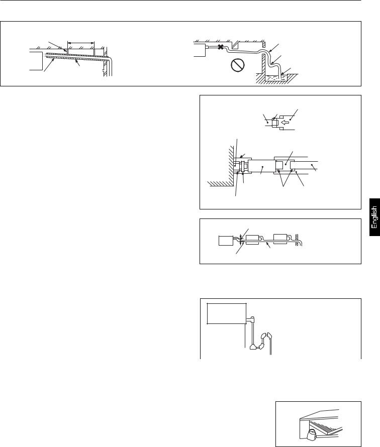
Installation Procedure
Drain Piping
(a)Drain piping should always be in a downhill grade (1/50~1/100) and avoid riding across an elevation or making traps.
|
Good piping |
Improper piping |
|
Suspension 1.5m ~ 2m |
|
Avoid riding across an elevation |
|
bolts |
|
|
|
|
|
Air vent |
Keep free from traps |
|
A downhill grade |
|
Do not pipe under water |
Heat |
|
|
|
of 1/100 or more |
|
|
|
insulation |
|
|
|
(b)When connecting the drain pipe to unit, pay suffcient attention not to apply excess force to the piping on the unit side. Also, fix the piping at a point as close as possible to the unit.
(c)For drain pipe, use hard PVC general purpose pipe VP-25(I.D.1") which can be purchased locally. When connecting, insert a PVC pipe end securely into the drain socket before tightening securely using the attached drain hose and clamp. Adhesive must not be used connection of the drain socket and drain hose (accessory).
(d)When constructing drain piping for several units, position the common pipe about 100 mm below the drain outlet of each unit as shown in the sketch. Use VP-30(11/4") or thicker pipe for this purpose.
(e)The stiff PVC pipe put indoor side should be heat insulated.
Stage
Drain socket difference Drain hose part
Drain socket |
|
Pipe cover(large) |
VP-25 joint |
[for insulation] |
(field purchased) |
(accessory) |
|
Main unit |
|
Drain hose |
VP-25 |
|
(accessory) |
(field purchased) |
|
Clamp |
Adhesion |
Pipe cover [for insulation] |
(accessory) |
|
(field purchased) |
Pipe cover(small) [for insulation] |
|
|
(accessory)
Secure the elevation as high as possible (approx. 100 mm)
VP-30
A downhill grade of 1/100 or more
(f)Avoid putting the outlet of drain hose in the places with irritant gas generated. Do not insert the drain hose directly into drainage, where the gas with sulfur may be generated.
(g)Because the drain spout is at the position, which negative pressure may occur. So with the rise of water level in the drain pan, water leakage may occur. In order to prevent water leakage,
we designed a backwater bend. The structure of backwater H1
bend should be able to be cleaned. As the right figure shown, |
|
|
|
H1=100mm or the static pressure of |
|
H2 |
|||||
use T type joint. The backwater bend is set near the air |
|||||
air sending motor |
|||||
conditioner. |
|
|
|
H2=1/2H1 (or between 50~100mm) |
|
As figure shown, set a backwater bend in the middle of drain |
|
|
|
|
|
|
|
|
|
||
hose. |
|
|
|
|
|
Drainage Test
(1)Conduct a drainage test after completion of the electrical work.
(2)During the trial, make sure that drain flows properly through the piping and that no water leaks from connections.
(3)In case of a new building, conduct the test before it is furnished with the ceiling.
(4) Be sure to conduct this test even when the unit is installed in the heating season.
Procedures
(a)Supply about 1000 cc of water to the unit through the air outlet using a feed water pump.
(b)Check the drain while cooling operation.
23
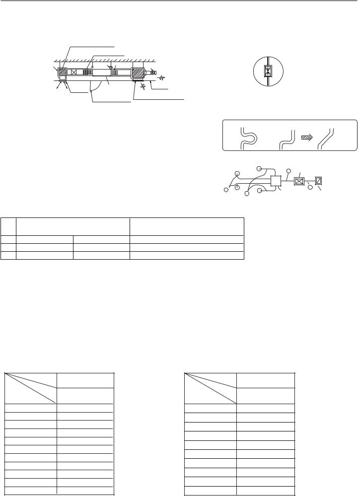
Installation Procedure
Air Duct
Please consult the after-sales service personnel for the choosing and installation of suction inlet, suction duct, discharging outlet and discharging duct. Calculating the design drawing and outer static pressure, and choose the discharging duct with proper length and shape.
|
muffler cavity (air sending) |
|
|
|
|
Sacking joint |
|
Insulation |
|
A |
Air volume adjuster |
|
Air outlet |
Air conditioner |
Ceiling |
|
main unit |
|
|
|
|
Air suction grille with air filter |
|
|
|
Checking meatus |
|
 The length difference among every duct is limited below 2:1.
 Reduce the length of duct as possible as can.
 Reduce the amount of bend as possible as can.
 Use heat insulation material to bind and seal the part connecting main unit and the flare part of air discharging duct. Perform duct installation work, before the fitment of ceiling.
Enlarging chart of profile chart A
Vibration resistance hook
Bad example |
Bad example |
Good example |
A Air conditioner
Calculation method of the dimension of the simple quadrate air duct
Presuming the unit length friction impedance of the duct is 1Pa/m, when the dimension of one side of the air duct is fixed as 250mm, as shown below:
B |
A |
|
|
Static pressure |
Equipped with |
||
A |
|||
|
box |
air filter (bought) |
AD362AHERA - AD482AHEAA - AD482AHERA AD282AHEAA - AD362AHEAA AD602AHEAA - AD602AHERA
|
Air volume |
Duct |
Air volume |
Duct |
A |
2400m3/h(40m3/min) |
250x560(mmxmm) |
1200m3/h (20m3/min) |
250x310(mmxmm) |
B |
600m3/h(10m3/min) |
250x190(mmxmm) |
300m3/h (5m3/min) |
250x120(mmxmm) |
The calculation of duct resistance (the simple calculation is as follow table)
Straight part |
Calculate as per 1m length 1Pa, 1Pa/m |
|
|
Bend part |
Each bend takes as a 3~4m long straight duct |
|
|
Air out part |
Calculate as 25Pa |
Static pressure box |
Calculate as 50Pa/each |
|
|
Air inlet grille (with air filter) |
Calculate as 40Pa/each |
The chosen chart of simple duct
Note:1Pa/m=0.1mmAg/m
Shape |
Square duct |
|
Air volume |
Item |
Dimension |
m3/h(m3/n) |
|
(mmxmm) |
100 |
|
250 x 60 |
200 |
|
250 x 90 |
300 |
|
250 x 120 |
400 |
|
250 x 140 |
500 |
|
250 x 170 |
600(10) |
|
250 x 190 |
800 |
|
250 x 230 |
1,000 |
|
250 x 270 |
1,200(20) |
|
250 x 310 |
1,400 |
|
250 x 350 |
1,600 |
|
250 x 390 |
Shape |
Square duct |
Air volume Item |
Dimension |
m3/h(m3/n) |
(mmxmm) |
1,800(30) |
250 x 430 |
2000 |
250 x 470 |
2400 |
250 x 560 |
3,000(50) |
250 x 650 |
3,500 |
250 x 740 |
4,000 |
250 x 830 |
4,500 |
250 x 920 |
5,000 |
250 x 1000 |
5,500 |
250 x 1090 |
6,000(100) |
250 x 1180 |
24
 Loading...