


Haier AB12SC2VHA, AB18SC2VHA, AD12SL2VHA, AD12SL2VHB, AD18SL2VHA Installation Guide
...Ductless Split Air Conditioner
Indoor |
Outdoor |
AW12LC2VH* |
1U12LC2VHA |
AW18LC2VH* |
1U18LC2VHA |
AD12SL2VH* |
|
AD18SL2VH* |
|
AB12SC2VH* |
|
AB18SC2VH* |
|
Installation Manual
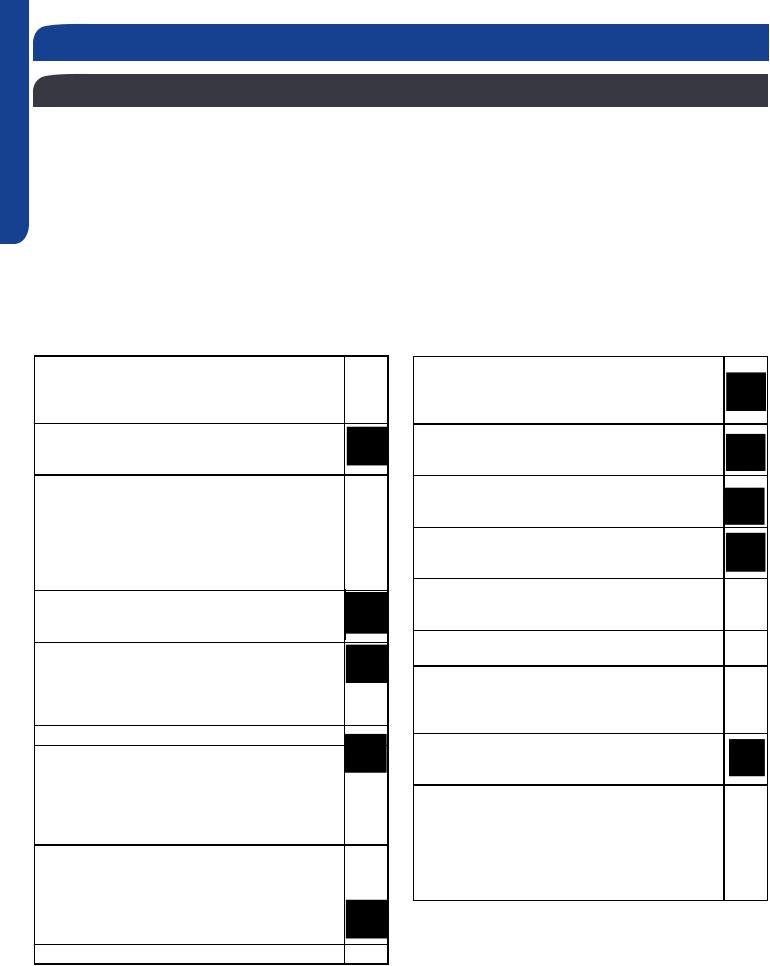
Table of Cont ents |
|
Nomenclature ............................................................................................................................... |
2 |
................................................................................................................... |
3 |
Safety ........................................................................................................................................... |
4 |
Section A - Outdoor Unit Installation ........................................................................................... |
7 |
Section B - Indoor Unit Installation - Wall Mount .......................................................................... |
13 |
Section C - Indoor Unit Installation - Cassette .............................................................................. |
17 |
Section D - Indoor Unit Installation - Slim Duct............................................................................. |
23 |
Section E - Wired Controller YR-E17 ............................................................................................. |
29 |
Section F - Wireless Remote Cotroller ........................................................................................... |
37 |
0010586610
ENGLISH
Nomenclature
Nomenclature
1 U18LCES 2 V H A
Unit |
Type |
|
|
|
|
|
A = Indoor Unit |
|
Product Revision |
||||
1 = Single Zone Outdo |
|
|||||
2 = Two Zone Outdoor |
|
|
||||
3 = Three Zone Outdo |
|
|
||||
4 = Four Zone Outdoor |
|
|
||||
|
Unit Type |
|
System Type |
|||
|
|
H = Heat Pump |
||||
|
U = Outdoor |
|
||||
|
|
C = Cool Only |
||||
|
B = Cassette Type Indoor |
|
||||
|
|
|
||||
|
D = Slim Duct Type Indoor |
|
|
|||
|
M = Mid Static Duct Type Indoor |
|
|
|
Compressor Speed |
|
|
|
|
||||
|
H = High Static Duct Type Indoor |
|
|
|
||
|
|
|
||||
|
W = Wall Mount Type Indoor |
|
V = Variable Speed |
|||
|
|
Nominal Capacity |
|
Voltage |
||
|
|
In Btu/hr (x 1000) |
Product Family |
1 = 115V |
||
|
|
|
|
|
- MS |
2 = 230V |
|
|
|
|
|
|
|
|
|
|
|
|
- LC |
|
|
|
|
|
|
- SL |
|
|
|
|
|
|
- SC |
|
PAGE 2 |
INTRODUCTION |

|
Outdoor |
1U12LC2VH |
1U18LC2VH |
1U12LC2VH |
1U18LC2VH |
1U12LC2VH |
1U18LC2VH |
|
|
|
|
|
|
|
|
|
|
|
|
|
System |
12LC |
18LC |
12LCSL |
18LCSL |
12LCSC |
18LCSC |
ENGLISH |
|
|
|
|
|
|
|
|
|
||
Model Name |
Outdoor |
1U12LC2VHA |
1U18LC2VHA |
1U12LC2VHA |
1U18LC2VHA |
1U12LC2VHA |
1U18LC2VHA |
||
|
|||||||||
|
|
|
|
|
|
|
|
|
|
|
Indoor |
AW12LC2VH* |
AW18LC2VH* |
AD12SL2VH* |
AD18SL2VH* |
AB12SC2VH* |
AB18SC2VH* |
|
|
|
|
|
|
|
|
|
|
|
|
Operating |
Cooling °F(°C) |
0~115(-18~46) |
0~115(-18~46) |
0~115(-18~46) |
0~115(-18~46) |
0~115(-18~46) |
0~115(-18~46) |
|
|
Range |
Heating °F(°C) |
5~75(-15~24) |
5~75(-15~24) |
5~75(-15~24) |
5~75(-15~24) |
5~75(-15~24) |
5~75(-15~24) |
|
|
|
|
|
|
|
|
|
|
|
|
Power Supply |
Voltage, Cycle, |
208-230/60/1 |
208-230/60/1 |
208-230/60/1 |
208-230/60/1 |
208-230/60/1 |
208-230/60/1 |
|
|
Phase V/Hz/- |
|
||||||||
|
|
|
|
|
|
|
|
||
|
Compressor Type |
|
DC Inverter Driven Rotary |
|
|
|
|
||
|
Maximum Fuse |
15 |
25 |
15 |
25 |
15 |
25 |
|
|
|
Size A |
|
|||||||
|
|
|
|
|
|
|
|
||
|
|
|
|
|
|
|
|
|
|
|
Minimum Circuit |
15 |
15 |
15 |
15 |
15 |
15 |
|
|
|
Amp A |
|
|||||||
|
|
|
|
|
|
|
|
||
|
|
|
|
|
|
|
|
|
|
|
Dimension: |
21 1/4 (540) |
27 (688) |
21 1/4 (540) |
27 (688) |
21 1/4 (540) |
27 (688) |
|
|
Outdoor Unit |
Height in (mm) |
|
|||||||
|
|
|
|
|
|
|
|||
|
|
|
|
|
|
|
|
|
|
|
Dimension: |
30 3/4 (780) |
31 7/8 (810) |
30 3/4 (780) |
31 7/8 (810) |
30 3/4 (780) |
31 7/8 (810) |
|
|
|
Width in (mm) |
|
|||||||
|
|
|
|
|
|
|
|
||
|
|
|
|
|
|
|
|
|
|
|
Dimension: |
9 5/8 (245) |
11 5/16 (288) |
9 5/8 (245) |
11 5/16 (288) |
9 5/8 (245) |
11 5/16 (288) |
|
|
|
Depth in (mm) |
|
|||||||
|
|
|
|
|
|
|
|
||
|
|
|
|
|
|
|
|
|
|
|
Weight (Ship/ |
75.4/68.8 |
100.3/94.8 |
75.4/68.8 |
100.3/94.8 (45.5/43) |
75.4/68.8 |
100.3/94.8 |
|
|
|
Net)- lbs (kg) |
(34.2/31.2) |
(45.5/43) |
(34.2/31.2) |
(34.2/31.2) |
(45.5/43) |
|
||
|
|
|
|||||||
|
|
|
|
|
|
|
|
|
|
|
Dimension: |
11(280) |
12 3/4 (322) |
7 5/16 (185) |
7 5/16 (185) |
10 1/4 (260) |
10 1/4 (260) |
|
|
|
Height in (mm) |
|
|||||||
|
|
|
|
|
|
|
|
||
|
|
|
|
|
|
|
|
|
|
|
Dimension: |
33 5/8 (855) |
39 1/4 (997) |
33 7/16 (850) |
46 1/16 (1170) |
22 7/16(570) |
22 7/16(570) |
|
|
|
Width in (mm) |
|
|||||||
|
|
|
|
|
|
|
|
||
|
|
|
|
|
|
|
|
|
|
|
Dimension: |
8 1/16 (204) |
9 1/4 (235) |
16 9/16 (420) |
16 9/16 (420) |
22 7/16(570) |
22 7/16(570) |
|
|
|
Depth in (mm) |
|
|||||||
|
|
|
|
|
|
|
|
||
|
|
|
|
|
|
|
|
|
|
|
Max. Ex ternal |
|
|
|
|
|
|
|
|
|
Static Pressure |
NA |
NA |
0.16 (40) |
0.16 (Pa) |
NA |
NA |
|
|
|
in.W.G(Pa) |
|
|
|
|
|
|
|
|
|
|
|
|
|
|
|
|
|
|
|
Drainpipe Size |
NA |
NA |
1 1/4 |
1 1/4 |
1 1/4 |
1 1/4 |
|
|
|
O.D. in |
|
|||||||
|
|
|
|
|
|
|
|
||
|
|
|
|
|
|
|
|
|
|
|
Internal Conden- |
NA |
NA |
Standard |
Standard |
Standard |
Standard |
|
|
|
sate Pump |
|
|||||||
|
|
|
|
|
|
|
|
||
|
|
|
|
|
|
|
|
|
|
|
Max. Drain-Lift |
NA |
NA |
27 9/16 (700) |
27 9/16 (700) |
27 9/16 (700) |
27 9/16 (700) |
|
|
|
height in(mm) |
|
|||||||
|
|
|
|
|
|
|
|
||
|
|
|
|
|
|
|
|
|
|
|
Grill Model |
NA |
NA |
P1B-890(O)/(I) |
P1B-1210(O)/(I) |
PB-700IB |
PB-700IB |
|
|
|
|
|
|
|
|
|
|
|
|
|
Weight (Ship/ |
26.9/22.05 |
35.3/28.7 |
47.2/36.8 |
62.4/51.4 |
61.3/47 |
61.3/47.0 |
|
|
|
Net)- lbs (kg) |
(12.2/10) |
(16/13) |
(21.4/16.7) |
(28.3/23.3) |
(27.8/21.3) |
(27.8/21.3) |
|
|
|
|
|
|
|
|
|
|
|
|
|
Connections |
Flare |
Flare |
Flare |
Flare |
Flare |
Flare |
|
|
|
|
|
|
|
|
|
|
|
|
|
Liquid O.D. in |
1/4 |
1/4 |
1/4 |
1/4 |
1/4 |
1/4 |
|
|
|
|
|
|
|
|
|
|
|
|
|
Suction O.D. in |
3/8 |
1/2 |
3/8 |
1/2 |
3/8 |
1/2 |
|
|
Refrigerate |
Factory Charge |
42.32 |
45.86 |
42.32 |
45.86 |
42.32 |
45.86 |
|
|
Oz |
|
||||||||
Line |
|
|
|
|
|
|
|
||
|
|
|
|
|
|
|
|
||
|
Maximum Line |
50/15 |
83/25 |
50/15 |
83/25 |
50/15 |
83/25 |
|
|
|
Length Ft / m |
|
|||||||
|
|
|
|
|
|
|
|
||
|
|
|
|
|
|
|
|
|
|
|
Maximum Height |
33/10 |
50/15 |
33/10 |
50/15 |
33/10 |
50/15 |
|
|
|
Ft / m |
|
|||||||
|
|
|
|
|
|
|
|
||
|
|
|
|
|
|
|
|
|
|
INTRODUCTION |
PAGE 3 |
SAFETY OVERVIEW
ENGLISH
Read These Safety Precautions
Besuretoreadthesafetyprecautionsbeforeconductingwork.Theitemsareclassifiedinto“Warning”and“Caution.”The “Warningitemsareespeciallyimportantsincetheycanleadtodeathorseriousinjuryifnotfollowedclosely. The“Caution” items can also lead to serious accidents under some conditions if they are not followed. Therefore, be sure to observe all safety precautions listed here.
∆ This symbol means be careful when doing this procedure or touching this equipment.
ᴏ This symbol indicates a prohibited action.
•This symbol means that an action must be taken; the action will be listed next to the symbol.
After the repair work is complete, be sure to conduct a test operation to ensure that the equipment operates properly; explain the safety precautions for operating the equipment to the customer.
Warning
Disconnect the power cable from electrical socket before disassembling equipment for repair. Working on equipment that is connected to a power supply can cause an electrical shock.
If the refrigerant gas discharges during the repair work DO NOT touch the discharging refrigerant gas. The refrigerant gas can cause frostbite.
Before disconnecting the suction or discharge pipe of the compressor at the welded section, recover the refrigerant gas in a well-ventilated area. If refrigerant gas remains inside the compressor, the refrigerant gas or the refrigerating machine oil will discharge when the pipe is disconnected and may causeinjury.
If the refrigerant gas leaks during the repair work, ventilate the area. The refrigerant gas can generate toxicgaseswhenitcontactsflames.
The step-up capacitor supplies high-voltage electricity to the electrical components of the outdoor unit. Be sure to discharge the capacitor completely before conducting repair work. A charged capacitor can cause electrical shock.
Be sure to use parts listed in the service parts of the applicable model and appropriate tools to conduct repair work. Never attempt to modify
the equipment. The use of inappropriate parts or tools can cause electrical shock, excessive heat generation,orfire.
When relocating the equipment make sure that thenewinstallationsitehassufficientstrenghtto withstand the weight of the equipment. If the new installationsitedoesnothavesufficientstrength and if the installation work is not conducted securely,theequipmentcanfallandcauseinjury.
Be sure to install the product correctly by using the standard installation frame provided. Incorrect use of the installation frame and improper installation cancauseequipmenttofall,resultingininjury.
Do not repair the electrical components with wet hands. Working on equipment with wet hands can cause electrical shock.
Do not clean the equipment by splashing water. Washing the unit with water can cause an electrical shock.
Make sure that the unit is grounded when reparing the equipment in a wet or humid place to avoid electrical shocks.
Besuretoturnoffthepowerswitchwhencleaning the equipment; the internal fan rotates at a high speedandmaycauseinjury.
Do not tilt the unit when removing it. Water inside theunitcanspill,wettingthefloor.
Be sure to check that the refrigeration cycle section hascooleddownsufficientlybeforeconducting repair work. Working on the unit when the refrigerating cycle is hot can cause burns.
Use the welder in a well-ventilated place. Using the welder in an enclosed room can cause oxygen deficiency.
Be sure to use a dedicated power circuit for the equipment; follow appropriate technical standards for the electrical equipment, the internal wiring regulations, and the instruction manual for installation when conducting electrical work.
Insufficientpowercircuitcapacityandimproper electricalworkcancause anelectricalshockorfire.
PAGE 4 |
INTRODUCTION |

SAFETY OVERVIEW
Read These Safety Precautions
Besuretousethespecifiedcabletoconnect between the indoor and outdoor units. Make the connections securely and route the cable properly so that there is no force pulling the cable at the connection terminals.
When connecting the cable between the indoor and outdoor units make sure that the terminal cover doesnotliftoffordismountbecauseofthecable.
If the cover is not mounted properly, the terminal connection section can cause an electrical shock, excessiveheatgeneration,orfire.
Do not damage or modify the power cable.
Damagedormodifiedpowercablescancause electricalshockorfire.Placingheavyitemsonthe power cable and heating or pulling the power cable can damage the cable.
Donotmixairorgasotherthanthespecified refrigerant (R=4 10A/R22) in the refrigerant system. If air enters the refrigerant system, an excessively high pressure results, causing equipment damage andinjury.
If the refrigerant gas leaks, be sure to locate the leak and repair it before charging the refrigerant. If the leak cannot be located and the repair work cannot be stopped, be sure to perform pump-down and close the service valve to prevent the refrigerant gas from leaking into the room. The refrigerant gas itself is harmless, but it can generate toxic gases whenitcontactsflames,suchasfanandother heaters or stoves and ranges.
When replacing the remote control battery, be sure to safely dispose of the battery to prevent children from swallowing it.
Do not install the equipment in a place where there is a possibility of combustable gas leaks. If combustible gas leaks and remains near the unit, it maycauseafire.
Be sure to install the packing and seal on the installation frame correctly. If the packing and seal are not properly installed, water can spill out, wettingfurnitureandthefloor.
Replace power cables and lead wires if they are scratched or deteriorated. Damaged cable and wires can cause electrical shock, excessive heat generation,orfire.
Check to see if the parts are mounted correctly, that the wires are connected correctly, and that connections at soldered or crimped terminals are secure. Improper installation and connections can cause excessive heat generation, electrical shock, andfire.
If the installation platform or frame has deteriorated or corroded, replace it. Corroded platform or frames cancausetheunittofall,resultingininjury.
Check to make sure that the equipment is grounded. Repair it if it is not properly grounded. Improper grounding can cause an electrical shock.
Be sure to measure the installation resistance of the repair. Be sure that the resistance is 1 M ohm or higher. Faulty installation can cause an electric shock.
Be sure to check the drainage of the indoor unit after the repair. Faulty drainage can cause the water tospill,wettingthefurnitureandthefloor.
Important Safety Related Installation Information
Indoor Clearances: If noncompliant may lead to temperature control complaints.
Wire Sizing: If noncompliant may lead to communication errors and inverter irregular operation.
Splices in Field Wiring: Splices between the wires that connect between the outdoor and indoor unit should be avoided. Communication errors may occur if noncompliant.
Sealing Penetrations: If penetrations at back of unit are not sealed, unconditioned air may be drawn into the back of the indoor wall mount unit. Temperature control and capacity complaints may occur.
ENGLISH
INTRODUCTION |
PAGE 5 |
[This page intentionally left blank.]

Section A - Outdoor Unit Installation
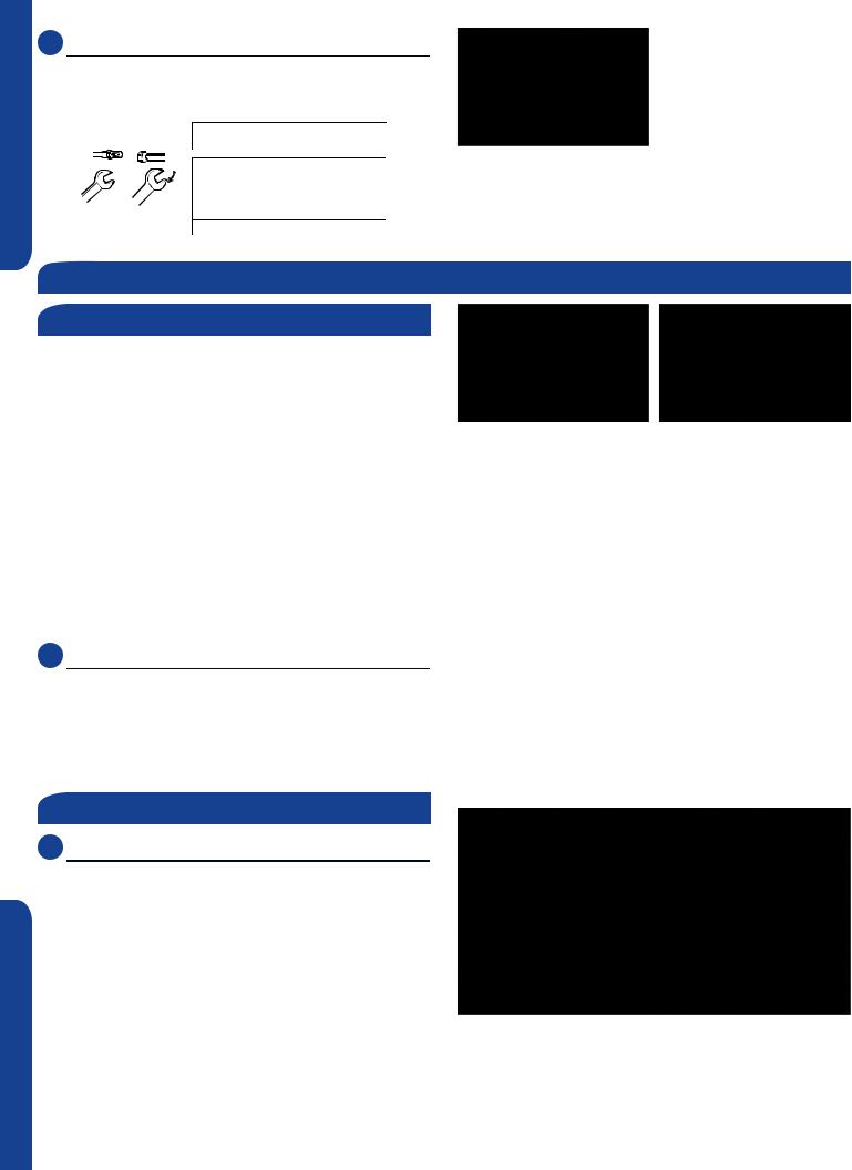
Step 1 - Installation of the Outdoor Unit
Attaching Drain Elbow to Outdoor Unit
(Heat Pump models only)
1.1 Step - 1.1
If attaching the supplied drain elbow to the outdoor unit, do so prior to attaching the refrigerant lines and wiring.
Step 1.1 |
Step1.2 |
Electrical Connections for the Outdoor Unit
1.2 Step - 1.2
Remove the cover plate of the outdoor unit to expose the terminal block connections.
1.3 Step - 1.3
Connect the wiring for both the power source and indoor wiring.
Wire the system according to applicable national / local codes.
Verify that the wiring connections for the indoor unit match
wire for wire. Step 1.3 (1-1, 2-2, 3-3, Gnd-Gnd). Failure to wire the system correctly
may lead to improper operation or component damage.
1.4 Step - 1.4
Replace the cover plate.
Step 2 - Interconnecting the Indoor and Outdoor Units
*See indoor section A, B, or C for electrical connections.
CAUTION
Step 1.4
Outdoor unit
Piping
The standard lineset length is 25ft. If the installation length is 12K,
18K model. (Illustration 4)
outdoor unit valves.
B Indoor unit A
Outdoor unit
Outdoor unit
Oil trap
Indoor unit
B
AIndoor unit
●Max. Elevation: A Max
=33ft / 10m (09k / 12k)
=50ft / 15m (18k / 24k)
●In case the height of A is more than 15ft / 5m, an oil trap should be installed every 16-23ft /5-7m
●Max. Length: B Max
=50ft / 15m (09k / 12k)
=83ft / 25m (18k / 24k)
chart.
2.1 Step - 2.1 |
|
Illustration 4 |
|
|
|
Refrigerant piping connections for the mini-split system are |
|
|
use caution to prevent dirt or debris from entering the tubing. |
|
|
Remember to place the nut on the pipe before creating the |
|
|
2.2 Step - 2.2 |
Step 2.1 |
Step 2.2 |
To join the lineset piping together, directly align the piping |
|
|
connection. |
|
|
ENGLISH
A SECTION
INSTALLATION |
PAGE 7 |
ENGLISH
2.3 Step - 2.3
Twowrenchesarerequiredtojointheflareconnections,one standard wrench, and one torque wrench. See Table 1 for the specifictorqueperpipingdiameter.
Half union |
Flare nut |
Forced fastening without careful centering may |
|
|
damage the threads and cause a leakage of gas. |
|
|||
|
|
Pipe Diameter(ǿ) |
Fastening torque |
Step 2.3 |
|
|
Liquid side6.35mm(1/4") |
18N.m/13.3Ft.lbs |
|
|
|
Liquid/Gas side9.52mm(3/8") |
42 N.m/30.1Ft.lbs |
|
Spanner |
Torque wrench |
Gas side 12.7mm(1/2") |
55N.m/40.6Ft.lbs |
|
Gas side 15.88mm(5/8") |
60 N.m/44.3Ft.lbs |
|
||
|
|
|
||
Table 1
Step 3 - Leak Test and Evacuation
SECTION A
Leak Test
HazardofExplosion!Neveruseanopenflametodetectgas |
|
|
leaks. Explosive conditions may occur. Use a leak test solution |
|
|
or other approved methods for leak testing. Failure to follow |
|
|
recommended safe leak test procedures could result In death |
|
|
orseriousinjuryorequipmentorpropertydamage. |
Step 3.2 |
|
Step 3.1 |
||
Use only dry nitrogen with a pressure regulator for |
|
|
pressurizing unit. Do not use acetylene, oxygen or |
|
|
compressed air or mixtures containing them for pressure |
|
|
testing. Do not use mixtures of a hydrogen containing |
|
|
refrigerant and air above atmospheric pressure for pressure |
|
|
testingastheymaybecomeflammableandcouldresultin |
|
|
an explosion. Refrigerant, when used as a trace gas should |
|
|
only be mixed with dry nitrogen for pressurizing units. Failure |
|
|
to follow these recommendations could result in death or |
|
|
seriousinjuryorequipmentorpropertydamage. |
|
|
3.1 Step - 3.1 |
|
|
Using a tank of nitrogen with attached regulator, charge the |
|
|
system with 150 PSIG of dry nitrogen. Use adapter AD-87 |
|
|
(fieldsupplied)toconnecttothevalve.Checkforleaksatthe |
|
|
flarefittingsusingsoapbubblesorotherdetectionmethods. |
|
|
If a leak is detected, repair and recheck. If no leaks are |
|
|
detected, proceed to evacuate the system. |
|
|
System Evacuation |
|
|
3.2 Step - 3.2 |
|
|
Attach a manifold gauge, micron gauge, and vacuum pump |
|
|
tothesuctionlineportusingadapterAD-87(fieldsupplied). |
|
|
(Illustration 5) |
|
|
Evacuate the system to 350 microns. |
|
|
Close the vacuum pump valve and check the micron |
|
|
gauge. If the gauge rises above 500 microns in 60 seconds, |
|
|
evacuation is incomplete or there is a leak in the system. If |
|
|
the gauge does not rise above 500 microns in 60 seconds, |
Illustration 5 |
|
evacuation is complete. |
||
|
PAGE 8 |
INSTALLATION |
3.3 Step - 3.3
Remove the adapter and hose connection from the suction line port, and replace the cap.
3.4 Step - 3.4A & 3.4B
Remove the cap from the liquid line valve. Using the hex wrench, open the valve, then replace and tighten the cap.
3.5 Step - 3.5A & 3.5B
Remove the cap from the suction line valve. Using the hex wrench, open the valve, then replace and tighten the cap.
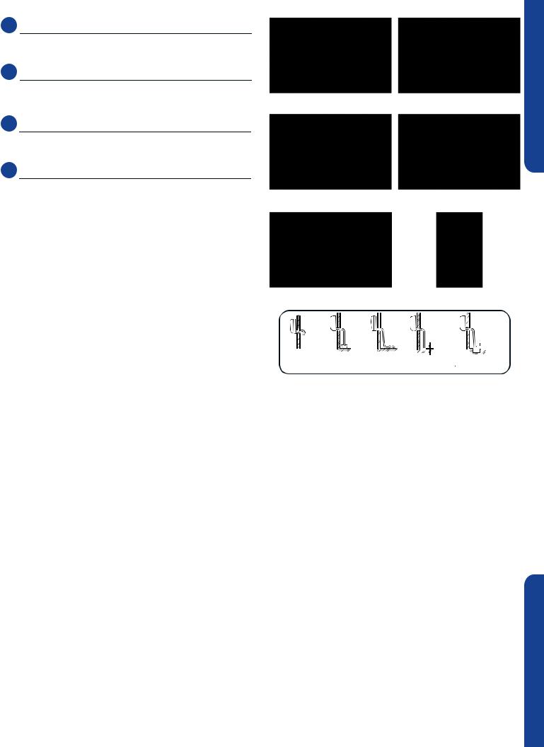
3.6 Step - 3.6
Wrap the lineset, drain line, and wiring starting at the bottom of the bundle with an overlap type wrap, concluding at the piping hole. Use a sealant to seal the piping hole opening
to prevent weather elements from entering the building. (Illustration 6)
Verify the condensate drain line has a constant pitch downwardforproperwaterflow.Thereshouldbenokinks orrisesinthetubingwhichmaycauseatrappingeffect resulting in the failure of the condensate to exit the piping.
Step 3.3 |
Step 3.4A |
Step 3.4B |
Step 3.5A |
Step 3.5B |
Step 3.6 |
|
|
|
Less than |
|
|
5cm |
It becomes |
The end is imm- |
It waves. The gap with the There is the bad |
high midway. |
ersed in water. |
ground is too small smell from a sewer |
Illustration 6
ENGLISH
A SECTION
INSTALLATION |
PAGE 9 |
ENGLISH
Step 4 - Charging
See Steps 5.2 - 5.5 for evacuating the system prior to |
System Test |
|
charging. The standard lineset length is 25ft. If the installation |
||
|
||
lengthisdifferent,adjusttherefrigerantchargeby.2oz/ft. |
Please kindly explain to our customers how to operate |
|
forthe9K,12K,18K,and24Kmodel.(Step4-Illustration4) |
||
through the instruction manual. |
||
|
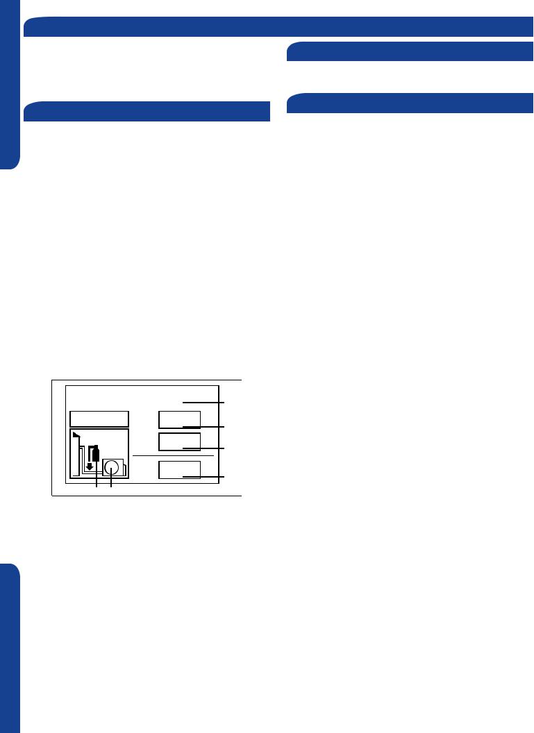
Refrigerant Charge Label
Thisproductcontainsfluorinatedgreenhousegasescovered bytheKyotoProtocol.Donotventintotheatmosphere.
Refrigerant type: R410A GWP* value: 1975
GWP = global warming potential
Pleasefillinwithindelibleink,
•1thefactoryrefrigerantchargeoftheproduct
•2theadditionalrefrigerantamountchargedinthefieldand
•1+2thetotalrefrigerantchargeontherefrigerantcharge label supplied with the product.
Thefilledoutlabelmustbeadheredintheproximityofthe product charging port (e.g. onto the inside of the stop valve cover).
A-containsfluorinatedgreenhousegasescoveredbythe KyotoProtocol
B - factory refrigerant charge of the product: see unit name plate
C-additionalrefrigerantamountchargedinthefield
D - total refrigerant charge E - outdoor unit
F - refrigerant cylinder and manifold for charging
Check Items for Test Run
Put check mark √ in boxes
No gas leak from linesets?
Are the linesets insulated properly?
Aretheconnectingwiringsofindoorandoutdoorfirmly inserted to the terminal block?
Istheconnectingwiringofindoorandoutdoorfirmly fixed?
Is condensate draining correctly?
Is the ground wire securely connected? Is the indoor unit securelyfixed?
Is power source voltage correct according to local code?
Is there any noise?
Is the lamp normally lighting?
Are cooling and heating (when in heat pump) performing normally?
Is the operation of room temperature sensor normal?
Contains fluorinated greenhouse gases |
|
covered by the Kyoto Protocol |
A |
R410A |
1= |
oz |
B |
|
2 |
2= |
oz |
C |
|
1 |
||||
|
|
|
||
|
1+2= |
oz |
D |
|
|
|
|
F E
SECTION A
PAGE 10 |
INSTALLATION |
Section 5 - Explaining Operation to the End User
•Using the OPERATING INSTRUCTIONS, explain to the user how to use the air conditioner (the remote controller, removing theairfilters,placingorremovingtheremotecontrollerfromtheremotecontrollerholder,cleaningmethods,precautionsfor operation, etc.)
•Recommend that the user read the OPERATING INSTRUCTIONS carefully.
Section 6 - Seacoast Application
•The outdoor unit should be installed at least ½ mile away from the salt water, including seacoasts and inland waterways. If the unit installed from ½ mile to 5 miles away from the salt water, including seacoasts and inland waterways, please follow the installation instruction below.
•Install the outdoor unit in a place (such as near buildings etc.) where it can be protected from sea breeze which can damage the outdoor unit.
|
|
ODU |
Sea breeze |
|
Sea breeze |
|
|
ODU |
Sea |
ODU |
Sea |
|
• If you cannot avoid installing the outdoor unit by the seashore, construct a protection wall around it to block the sea breeze.
|
|
|
|
|
|
|
|
• A protection wall should be constructed with a solid material such as |
Protection walls |
|
|
concrete to block the sea breeze and the height and the width of the wall |
|||||
|
||||||||
|
|
|
|
|
|
ODU |
should be 1.5 times larger than the size of the outdoor unit. Also, secure |
|
|
|
|
|
|
|
|
|
over 28 in (700mm) between the protection wall and the outdoor unit for |
Sea breeze |
|
|
|
|
|
|
|
exhausted air to ventilate. |
|
|
|
|
|
||||
|
|
|
|
|
|
|
||
|
|
|
|
|
|
|
|
|
ODU
Sea
•Install the outdoor unit in a place where water can drain smoothly.
•Ifyoucannotfindaplacesatisfyingaboveconditions,pleasecontactmanufacturer.Makesuretocleantheseawaterandthe dust on the outdoor unit heat exchanger.
ENGLISH
A SECTION
INSTALLATION |
PAGE 11 |
[This page intentionally left blank.]
Section B - Indoor Unit Installation - Wall Mount
Step 1 - Preparation
Required Tools for Installation
•Drill
•Wire Snipper
•HoleSaw23/4”
•Vacuum pump
•Soap-and-water solution or gas leakage detector
•Torque wrench
•17mm, 22mm, 26mm
•Tubing cutter
•Flaring tool
•Razor knife
•Measuring tape
•Level
•Micron gauge
•Nitrogen
•Mini-SplitAD-87Adapter(1/4”to5/16”)
•A - Non-adhesive Tape
•B - Adhesive Tape
•C - Saddle (L.S.) with screws
•D - Electrical wiring
•E - Drain hose (Included)
•F - Insulation
•G - Piping hole cover (Included)
Procedure for Selecting the Location
•Choose a place solid enough to bear the weight and vibration of the unit and where theoperationnoisewillnotbeamplified.
•Choose a location where the hot air discharged from the unit or the operation noise and will not cause a nuisance to the neighbors of the user.
•Theremustbesufficientspacefor carrying the unit into and out of the site.
•Theremustbesufficientspaceforair passage and no obstructions around the air inlet and air outlet.
•The site must be free from the possibility offlammablegasleakageinanearby place.
•Locate the unit to avoid noise and discharged hot air will not annoy the neighbors.
•Install units, power cords and inter-unit cables at least 10ft away from television and radio sets. This is to prevent interference to images and sounds. (Noise may be heard even if they are more
than 10ft away depending on radio wave conditions.)
•Sincedrainflowsoutoftheoutdoorunit, do not place anything under the unit that must be kept away from moisture.
Note:
1)Cannot be installed hanging from ceiling or stacked.
2)If installing on a high place such as a roof, with a fence or guard rail around it.
3)If there is a potential for accumulated snow to block the air inlet or heat exchanger, install the unit on a higher base.
4)R-410A refrigerant is a safe, nontoxic and nonflammablerefrigerant.However,if there is a concern about a dangerous level of refrigerant concentration in the case of refrigerant leakage, add extra ventilation.
5)Avoid installing the outdoor unit where corrosive gases, such as sulfur oxides, ammonia, and sulfurous gas, are produced. If unavoidable, consult with an installation specialist about using a corrosion-proof or anti-rust additive to protect the unit coils.
ENGLISH
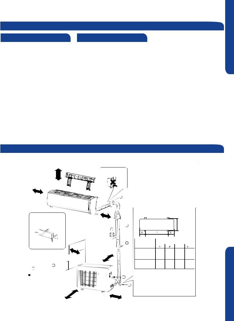
Clearances of Indoor and Outdoor Units
Thispictureisforreferenceonly.Yourproductmaylookdifferent.Readthismanualbeforeinstallation.Explaintheoperationoftheunittotheuseraccordingto this manual.
The models adopt HFC free refrigerant R410A
more than 2in. |
Attention must be paid to |
the pitch of drain hose |
more than 4in.
more than 4in.
 The marks from A to G in the
  gure are the name of the parts.
The distance between the indoor unit and the  oor should be more than 6 feet.
more than 24in.
Floor fixing dimensions of the outdoor unit (Unit: inch)
more than 4in.
|
|
|
|
Z |
|
|
1 |
|
2 |
|
|
C |
Model |
Dimensions(inches) |
|
||
|
|
|
|
||
|
1 |
|
x2 |
|
|
|
|
|
|
||
more than 4in. |
1U12LC2VHA |
5 1/2” |
19 5/8” |
5 1/2” |
10 1/16” |
|
|
|
|
|
|
|
1U18LC2VHA |
4 1/2” |
23” |
4 1/2” |
12 5/8” |
|
Fixing of outdoor unit |
|
|
|
|
 Fix the unit to concrete or block with bolts (10mm) securely.
 When
When tting the unit to wall surface, roof or rooftop,
 x the unit securely in consideration of earthquake and strong wind.
 If vibration may affect the house,
 x the unit by attaching a vibration-proof mat.
more than 6in.
B SECTION
INSTALLATION |
PAGE 13 |
 Loading...