


OPERATING MANUAL |
|
OPERATING MANUAL |
|||||
BEDIENUNGSANLEITUNG |
|||||||
|
|
|
|
||||
|
|
|
|
|
|
MODE D’EMPLOI |
|
AIR CONDITIONER |
|
|
|
|
|
||
|
MANUAL DE FUNCIONAMIENTO |
||||||
CASSETTE TYPE |
|||||||
MANUALE DI ISTRUZIONI |
|||||||
|
|
|
|
ΕΓ ΕΙΡΙ∆Ι ΛΕΙΤ ΥΡΓΙΑΣ |
|||
|
|
|
|
РУКОВОДСТВО ПО ЭКСПЛУАТАЦИИ |
|||
|
|
|
|
MANUAL DE INSTRUÇÕES |
|||
|
|
|
|
|
|
|
|
|
|
|
|
|
|
|
|
|
|
|
|
|
|
|
|
|
|
|
|
|
|
|
|
|
|
|
|
|
|
|
|
|
|
|
|
|
|
|
|
|
|
|
|
|
|
|
|
|
|
|
|
|
|
|
|
|
|
|
|
|
|
|
|
|
|
|
|
|
|
|
|
|
|
|
|
|
|
|
|
|
|
|
|
|
|
|
|
|
|
|
|
|
|
|
|
|
|
|
|
|
|
|
|
|
|
|
|
|
|
|
|
|
|
|
|
|
|
|
|
|
|
|
|
|
|
|
|
|
|
|
|
|
|
|
|
|
|
|
|
|
|
|
|
|
|
|
|
|
|
|
|
|
|
|
|
|
|
|
|
|
|
|
|
|
|
|
|
|
|
|
|
|
|
|
|
|
|
|
|
|
|
|
|
|
|
|
|
|
|
|
|
|
|
|
|
|
|
|
|
|
|
|
|
|
|
|
|
|
|
|
|
|
|
|
|
|
|
|
|
|
|
|
|
|
|
|
|
|
|
|
|
|
|
|
|
|
|
|
|
|
|
|
|
|
|
|
|
|
|
|
|
|
|
|
|
|
|
|
|
|
|
|
|
|
|
|
|
|
|
|
|
|
|
|
|
|
|
|
|
|
|
|
|
|
|
|
|
|
|
|
|
|
|
|
|
|
|
|
|
|
|
|
|
|
|
|
|
|
|
|
|
|
|
|
|
|
|
|
|
|
|
|
|
|
|
|
|
|
|
|
|
|
|
|
|
|
|
|
|
|
|
|
|
|
|
|
|
|
|
|
|
|
|
|
|
|
|
|
|
|
|
|
|
|
|
|
|
KEEP THIS OPERATION MANUAL |
P/N9369320033 |
|
FOR FUTURE REFERENCE |
||
|
 EλληvIkά Italiano Español Français Deutsch English
 Português Русский
CONTENTS
SAFETY PRECAUTIONS ....................................... |
1 |
FEATURES AND FUNCTIONS .............................. |
2 |
NAME OF PARTS ................................................... |
3 |
PREPARATION ....................................................... |
5 |
OPERATION ........................................................... |
6 |
TIMER OPERATION ............................................... |
8 |
SLEEP TIMER OPERATION ................................... |
9 |
ADJUSTING THE DIRECTION OF |
|
AIR CIRCULATION ............................................... |
10 |
SWING OPERATION ............................................ |
10 |
ENERGY SAVE OPERATION ............................... |
11 |
MANUAL AUTO OPERATION ............................. |
11 |
CLEANING AND CARE ........................................ |
12 |
TROUBLESHOOTING .......................................... |
13 |
OPERATING TIPS ................................................. |
14 |
SAFETY PRECAUTIONS
●Before using the appliance, read these “PRECAUTIONS” thoroughly and operate in the correct way.
●The instructions in this section all relate to safety; be sure to maintain save operating conditions.
●“DANGER”, “WARNING” and “CAUTION” have the following meanings in these instructions:
DANGER! |
This mark indicates procedures which, if improperly performed, are most likely to |
|
result in the death of or serious injury to the user or service personnel. |
||
|
||
|
|
|
WARNING! |
This mark indicates procedures which, if improperly performed, might lead to the |
|
death or serious injury of the user. |
||
|
|
|
CAUTION! |
This mark indicates procedures which, if improperly performed, might possibly result |
|
in personal harm to the user, or damage to property. |
||
|
||
|
|
DANGER!
CAUTION!
●Do not attempt to install this air conditioner by yourself.
●This unit contains no user-serviceable parts. Always consult authorized service personnel for repairs.
●When moving, consult authorized service personnel for disconnection and installation of the unit.
●Do not become over-exposed to cold air by staying in the direct path of the airflow of the air conditioner for extended periods of time.
●Do not insert fingers or objects into the outlet port or intake grilles.
●Do not start and stop air conditioner operation by turning off the electrical breaker and so on.
●In the event of a malfunction (burning smell, etc.), immediately stop operation, turn off the electrical breaker, and consult authorized service personnel.
●Provide occasional ventilation during use.
● Do not direct air flow at fireplaces or heating apparatus.
●Do not climb on, or place objects on, the air conditioner.
●Do not hang objects from the indoor unit.
●Do not set flower vases or water containers on top of air conditioners.
●Do not expose the air conditioner directly to water.
●Do not operate the air conditioner with wet hands.
●Turn off power source when not using the unit for extended periods.
●Always turn off the electrical breaker whenever cleaning the air conditioner or the air filter.
●Connection valves become hot during Heating; handle with care.
●Check the condition of the installation stand for damage.
●Do not place animals or plants in the direct path of the air flow.
●When restarting after a long period of disuse in the winter, do: Turn the power switch on at least 12 hours before starting the unit.
●Do not drink the water drained from the air conditioner.
●Do not use in applications involving the storage of foods, plants or animals, precision equipment, or art works.
●Do not apply any heavy pressure to radiator fins.
●Operate only with air filters installed.
●Do not block or cover the intake grille and outlet port.
●Ensure that any electronic equipment is at least one metre away from each the indoor and outdoor units.
●Avoid installing the air conditioner near a fireplace or other heating apparatus.
●When installing the indoor and outdoor unit, take precautions to prevent access to infants.
●Do not use inflammable gases near the air conditioner.
En-1

FEATURES AND FUNCTIONS
AUTOMATIC OPERATION
Merely press the START/STOP button, and the unit will begin automatic operation in the Cooling or Dry mode as appropriate, in accordance with the thermostat setting and the actual temperature of the room.
SLEEP TIMER
When the SLEEP timer button is pressed during Cooling or Dry mode, the thermostat setting is gradually raised during the period of operation. When the set time is reached, the unit automatically turns off.
WIRELESS REMOTE CONTROL UNIT
The WIRELESS REMOTE CONTROL UNIT allows convenient control of air conditioner operation.
MILDEW-RESISTANT FILTER
The AIR FILTER has been treated to resist mildew growth, thus allowing cleaner use and easier care.
En-2

NAME OF PARTS
Fig. 1 |
|
|
|
|
|
Fig. 2 |
|
|
|
|
|
|
|
|
|
|
|
|
|
||
|
|
2 3 8 |
|
|
3 |
|
|
|||
|
|
|
|
|
|
|
|
4 5 6 |
7 |
|
|
|
|
|
|
|
|
|
SWING TIMER OPERATION |
|
|
|
1 |
|
|
|
|
Fig. 3 |
|
|
|
|
|
|
|
|
|
|
|
8 |
|
|
|
|
|
|
|
|
0 |
|
|
|
|
|
|
|
|
|
|
|
|
|
|
9 |
|
Fig. 4 |
Fig. 5 |
|
|
|
|
|
|
A |
A |
|
|
|
|
|
|
|
|
|
|||
|
|
|
|
|
|
A |
|
|
|
A |
|
|
|
|
|
|
|
|
|
|
|
|
|
|
|
A |
|
|
|
|
|
|
|
A |
|
|
|
|
A |
|
|
|
|
|
|
|
|
A |
|
|
|
|
|
|
|
|
|
|
|
|
|
|
|
|
|
|
|
|
|
|
|
|
|
|
B |
|
|
B |
|
|
|
B |
|
|
|
|
|
|
|
|
|
|
|
|
|
|
|
|
|
|
|
|
|
|
B |
|
|
|
|
Fig. 6 |
|
|
|
|
|
|
|
|
|
|
|
|
|
|
|
F |
|
|
|
|
|
|
C |
SLEEP |
TIMER |
G |
Q |
|
|
|
|
|
|
|
|
|
|
|
|
|
|||
|
|
|
|
|
|
|
|
|
||
|
|
CLOCK |
|
|
|
|
|
|
|
|
|
|
|
|
AUTO |
|
R |
|
|
|
|
|
|
COOL |
|
|
|
|
|
|
|
|
|
|
|
|
|
|
|
|
|
|
|
|
|
MASTER |
SET SET |
FAN |
|
CLOCK |
TIMER |
SLEEP |
|
|
|
|
CONTROL |
TEMP. TIME |
CONTROL |
|
|
|
|||
|
D |
|
|
|
H |
S |
|
ON |
U |
|
|
|
|
|
H |
M OFF |
|
||||
|
|
|
|
|
|
OFF |
ON TIMER RESET |
|
|
|
|
E |
|
START |
|
I |
A AUTO |
ENERGY SAVE |
AUTO |
V |
|
|
|
STOP |
|
COOL |
|
HIGH |
|
|||
|
|
|
|
|
|
|
|
|||
|
|
|
|
|
|
DRY |
|
MED |
|
|
|
|
|
|
|
J |
FAN |
|
LOW |
|
|
|
|
|
|
|
|
|
|
|
|
|
|
|
|
|
|
|
T |
|
|
W |
|
|
|
|
|
|
|
|
|
|
|
|
|
|
|
|
|
|
|
|
|
X |
|
|
|
|
|
|
|
|
|
|
Y |
|
|
K |
|
SET |
SWING |
N |
Fig. 8 |
|
|
|
|
|
SET |
SWING AIR FLOW |
|
|
|
|
||||
|
|
|
DIRECTION |
|
|
|
|
|||
|
L |
|
TIME TEST |
O |
|
|
|
|
|
|
|
ENERGYADJUST RUN ACL |
|
|
|
|
|
||||
|
|
SAVE |
|
|
|
|
|
|
||
|
M |
|
|
|
P |
|
|
|
|
|
|
|
|
|
|
|
|
|
|
|
|
|
Fig. 7 |
|
|
|
|
|
|
|
|
|
En-3 |
|
|
|
|
|
|
|
|
|
|
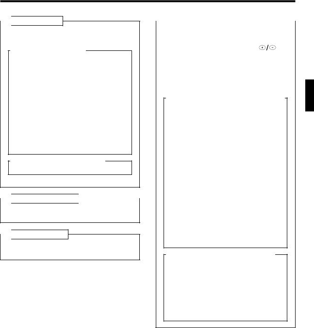
 Fig. 1 Indoor Unit
1 Air Filter
2 Horizontal Louvers
3 Indicator Lamps (Fig. 2)
4SWING Indicator Lamp (orange)
Lights during use of the SWING.
5TIMER Indicator Lamp (green)
Lights during use of the ON timer, OFF timer, PROGRAM timer, and SLEEP timer.
6OPERATION Indicator Lamp (red)
●Lights when unit is in operation.
●Flashes quickly for about one second when a signal is received from the remote control unit.
[When the OPERATION indicator and TIMER indicator flash alternately, it means that the power has been interrupted due to a power failure, etc.]
7 Remote Control Signal Receiver
8 Operating Control Panel (Fig.3)
9 MANUAL AUTO Button
0 Air Intake Grille
 Fig. 4 Electrical Breaker
This breaker is installed during the electrical instllation.
 Fig. 5 Outdoor Unit
A Air intake
B Air outlet
|
Fig. 6 Remote Control Unit |
|
|
|
|
|
|
|
|
|
|
|
C SLEEP Button |
|
|
|
D MASTER CONTROL Button |
|
|
|
E SET TEMP./SET TIME Buttons ( |
) |
|
|
F Signal Transmitter |
|
|
|
G TIMER Button |
|
|
|
H FAN CONTROL Button |
|
|
|
I START/STOP Button |
|
|
|
J Battery compartment lid |
|
|
Inside of the battery compartment lid (Fig. 7) K AIR FLOW DIRECTION Button
L ENERGY SAVE Button
MCODE CHANGE (Slide Switch)
Switching the remote control unit code. (Max. 4 units)
N TIME ADJUST Button
OTEST RUN Button
●This button is used when installing the air conditioner and should not be used under normal conditions as it will cause the air conditioner’s thermostat function to operate incorrectly.
●If this button is pressed during normal operation, the unit will switch to test operation mode, and the indoor unit’s OPERATION indicator lamp and TIMER indicator lamp will begin to flash simultaneously.
●To stop the test operation mode, either press the TEST RUN button once again, or press the START/STOP button to stop the air conditioner.
P ACL Button
Q Remote Control Unit Display (Fig. 8)
R Transmit Indicator
S Clock Display
T Operating Mode Display
U Timer Mode Display
V Fan Speed Display
W Temperature Set Display
X Timer Set Indicator
Y Temperature Set Indicator
En-4
 Loading...